Page 2354 of 3787
EI-24
< ON-VEHICLE REPAIR >
COWL TOP
COWL TOP
Removal and InstallationINFOID:0000000005929559
REMOVAL
1. Remove front wiper arm RH/LH from vehicle. Refer to WW-20, "Removal and Installation of Front Wiper
Arms".
2. Disconnect washer tube.
3. Remove fender seal and fender cover RH/LH.
4. Release the cowl top seal clips, then remove cowl top seal.
LIIA2565E
1. Fender cover 2. Fender seal3. Washer tube
4. Cowl top seal 5. Cowl extension panel6. Dual lock fastener
7. Double-faced adhesive tape 8. Cowl top cover 9. Clip C205
10. EPT sealer 11. Cowl extension clip12. Cover
Clip CE103 Vehicle front
PIIB2555J
Revision: May 2010 2011 Versa
Page 2355 of 3787
COWL TOPEI-25
< ON-VEHICLE REPAIR >
C
DE
F
G H
J
K L
M A
B
EI
N
O P
5. Release the cowl extension clip (1) by prying the center pawls apart and pulling clip outward. Remove remaining clips, then
remove cowl top cover (2).
6. Disconnect and remove the front wiper motor and linkage assembly. Refer to WW-22, "
Removal and Installation of Front
Wiper Drive Assembly".
CAUTION:
To avoid damage, make sure to cover the lower edge of
windshield with suitable protection material.
7. Remove cowl extension panel bolts, then remove cowl extension panel.
INSTALLATION
Installation is in the reverse order of removal.
NOTE:
• For wiper arm RH/LH installation and adjustment, Refer to WW-20, "
Removal and Installation of Front Wiper
Arms".
• Always replace EPT sealer and double-faced adhesive tape when installing cowl top cover.
LIIA2566E
PIIB6038E
Revision: May 2010 2011 Versa
Page 2367 of 3787
DOOR FINISHEREI-37
< ON-VEHICLE REPAIR >
C
DE
F
G H
J
K L
M A
B
EI
N
O P
3. Insert a trim stick (A) or suitable tool into back edge of front door power window and door lock/unlock switch finisher. Lift upward
to release the clips and remove.
4. Disconnect front door power window and door lock/unlock switch harness connector.
5. Remove the two front door finisher screws.
6. Release the clips, then lift front door finisher upward to remove it from door body panel.
Installation
Installation is in the reverse order of removal.
REAR DOOR
WIIA1237E
PIIB6042E
SIIA0810E
Revision: May 2010 2011 Versa
Page 2369 of 3787
DOOR FINISHEREI-39
< ON-VEHICLE REPAIR >
C
DE
F
G H
J
K L
M A
B
EI
N
O P
6. Release the clips, then lift rear door finisher upward to remove it from door body panel.
Installation
Installation is in the reverse order of removal.
SIIA0810E
Revision: May 2010 2011 Versa
Page 2370 of 3787

EI-40
< ON-VEHICLE REPAIR >
BACK DOOR TRIM
BACK DOOR TRIM
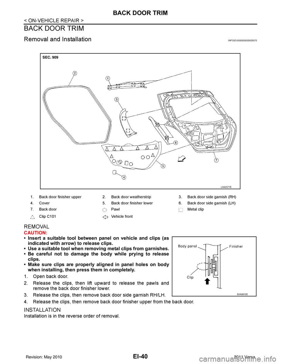
Removal and InstallationINFOID:0000000005929570
REMOVAL
CAUTION:
• Insert a suitable tool between panel on vehicle and clips (asindicated with arrow) to release clips.
• Use a suitable tool when removing metal clips from garnishes.
• Be careful not to damage the body while prying to release clips.
• Make sure clips are properly al igned in panel holes on body
when installing, then pr ess them in completely.
1. Open back door.
2. Release the clips, then lift upward to release the pawls and remove the back door finisher lower.
3. Release the clips, then remove back door side garnish RH/LH.
4. Release the clips, then remove back door finisher upper from the back door.
INSTALLATION
Installation is in the reverse order of removal.
1. Back door finisher upper 2. Back door weatherstrip 3. Back door side garnish (RH)
4. Cover 5. Back door finisher lower 6. Back door side garnish (LH)
7. Back door PawlMetal clip
Clip C101 Vehicle front
LIIA2577E
SIIA0810E
Revision: May 2010 2011 Versa
Page 2372 of 3787
EI-42
< ON-VEHICLE REPAIR >
BODY SIDE TRIM
Sedan Models
Removal and InstallationINFOID:0000000005929572
WARNING:
Do not reuse center pillar upper garnish if removed.
CAUTION:
• Insert a suitable tool between panel on vehicle and clips (asindicated with arrow) to release clips.
• Use a suitable tool when removing metal clips from garnishes.
• Be careful not to damage the body while prying to release clips.
• Make sure clips are properly al igned in panel holes on body
when installing, then pr ess them in completely.
WIIA1414E
1. Front pillar garnish 2. Front body side welt3. Front kicking plate inner
4. Front kicking plate outer 5. Center pillar lower garnish6. Rear kicking plate inner
7. Rear pillar finisher 8. Rear body side welt9. Rear kicking plate outer
10. Center pillar upper garnish PawlMetal clip
Clip Vehicle front
SIIA0810E
Revision: May 2010 2011 Versa
Page 2383 of 3787

HEADLININGEI-53
< ON-VEHICLE REPAIR >
C
DE
F
G H
J
K L
M A
B
EI
N
O P
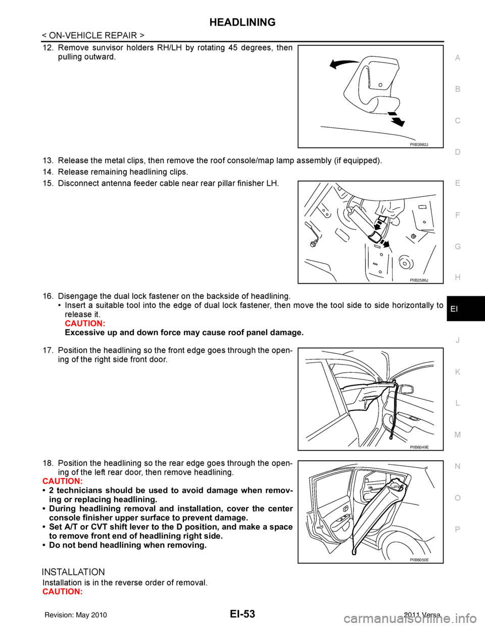
12. Remove sunvisor holders RH/LH by rotating 45 degrees, then pulling outward.
13. Release the metal clips, then remove the roof console/map lamp assembly (if equipped).
14. Release remaining headlining clips.
15. Disconnect antenna feeder cable near rear pillar finisher LH.
16. Disengage the dual lock fastener on the backside of headlining. • Insert a suitable tool into the edge of dual lock fa stener, then move the tool side to side horizontally to
release it.
CAUTION:
Excessive up and down force may cause roof panel damage.
17. Position the headlining so the front edge goes through the open- ing of the right side front door.
18. Position the headlining so the rear edge goes through the open- ing of the left rear door, then remove headlining.
CAUTION:
• 2 technicians should be used to avoid damage when remov-
ing or replacing headlining.
• During headlining removal and installation, cover the center
console finisher upper surface to prevent damage.
• Set A/T or CVT shift lever to the D position, and make a space
to remove front end of headlining right side.
• Do not bend headlining when removing.
INSTALLATION
Installation is in the reverse order of removal.
CAUTION:
PIIB3982J
PIIB2586J
PIIB6049E
PIIB6050E
Revision: May 2010 2011 Versa
Page 2385 of 3787

HEADLININGEI-55
< ON-VEHICLE REPAIR >
C
DE
F
G H
J
K L
M A
B
EI
N
O P
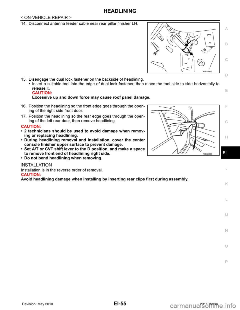
14. Disconnect antenna feeder cable near rear pillar finisher LH.
15. Disengage the dual lock fastener on the backside of headlining. • Insert a suitable tool into the edge of dual lock fa stener, then move the tool side to side horizontally to
release it.
CAUTION:
Excessive up and down force may cause roof panel damage.
16. Position the headlining so the front edge goes through the open- ing of the right side front door.
17. Position the headlining so the rear edge goes through the open- ing of the left rear door, then remove headlining.
CAUTION:
• 2 technicians should be used to avoid damage when remov-
ing or replacing headlining.
• During headlining removal and installation, cover the center
console finisher upper surface to prevent damage.
• Set A/T or CVT shift lever to the D position, and make a space
to remove front end of headlining right side.
• Do not bend headlining when removing.
INSTALLATION
Installation is in the reverse order of removal.
CAUTION:
Avoid headlining damage when installing by inserting rear clips first during assembly.
PIIB2586J
PIIB6049E
Revision: May 2010 2011 Versa