2011 NISSAN TIIDA Console
[x] Cancel search: ConsolePage 231 of 3787
AT-214
< SERVICE INFORMATION >
SHIFT CONTROL SYSTEM
REMOVAL
CAUTION:
Make sure that parking brake is applied before removal/installation.
1. Place the shift selector in the “N” position.
2. Remove the center console assembly. Refer to IP-11
.
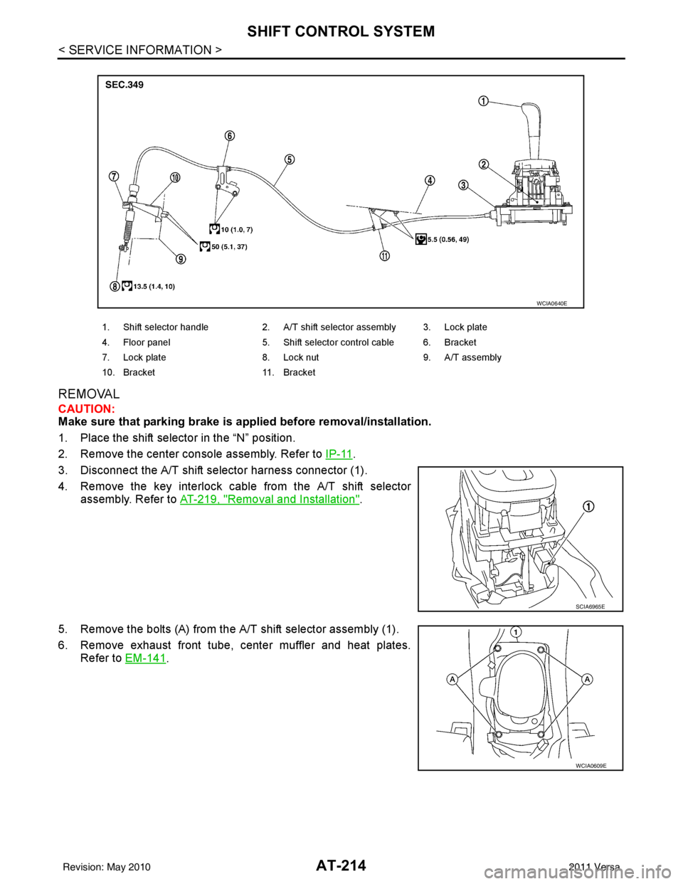
3. Disconnect the A/T shift selector harness connector (1).
4. Remove the key interlock cable from the A/T shift selector assembly. Refer to AT-219, "
Removal and Installation".
5. Remove the bolts (A) from the A/T shift selector assembly (1).
6. Remove exhaust front tube, center muffler and heat plates. Refer to EM-141
.
1. Shift selector handle 2. A/T shift selector assembly 3. Lock plate
4. Floor panel 5. Shift selector control cable 6. Bracket
7. Lock plate 8. Lock nut 9. A/T assembly
10. Bracket 11. Bracket
WCIA0640E
SCIA6965E
WCIA0609E
Revision: May 2010 2011 Versa
Page 236 of 3787
KEY INTERLOCK CABLEAT-219
< SERVICE INFORMATION >
DE
F
G H
I
J
K L
M A
B
AT
N
O P
KEY INTERLOCK CABLE
Removal and InstallationINFOID:0000000005928277
COMPONENTS
REMOVAL
CAUTION:
Make sure that parking brake is applie d before removal and installation.
1. Place the shift selector in the “N” position.
2. Remove the shift selector handle. Refer to AT-216, "
Shift Selector Handle Removal and Installation".
3. Remove the center console assembly. Refer to IP-11
.
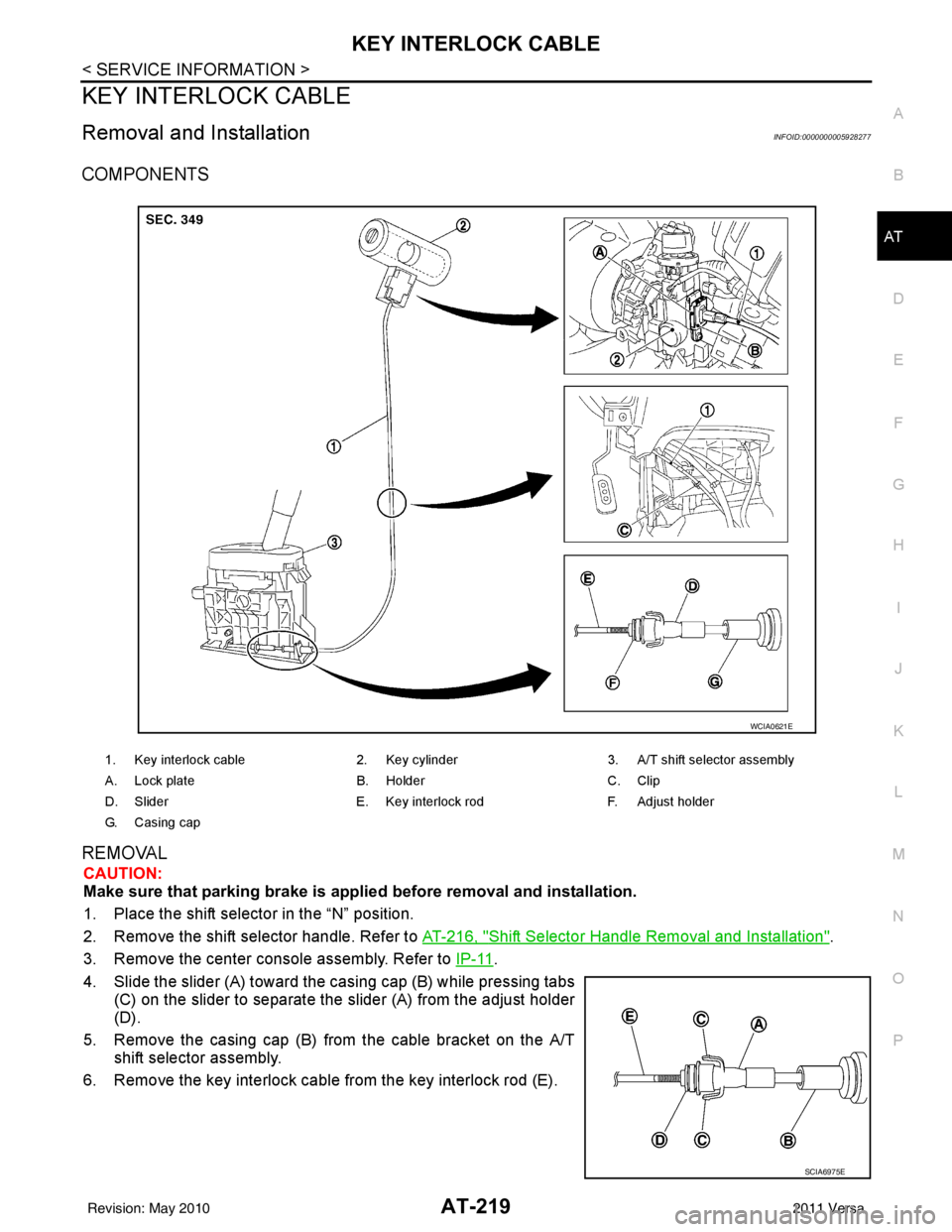
4. Slide the slider (A) toward the casing cap (B) while pressing tabs (C) on the slider to separate the slider (A) from the adjust holder
(D).
5. Remove the casing cap (B) from the cable bracket on the A/T shift selector assembly.
6. Remove the key interlock cable from the key interlock rod (E).
1. Key interlock cable 2. Key cylinder3. A/T shift selector assembly
A. Lock plate B. HolderC. Clip
D. Slider E. Key interlock rodF. Adjust holder
G. C a s i n g c a p
WCIA0621E
SCIA6975E
Revision: May 2010 2011 Versa
Page 238 of 3787
KEY INTERLOCK CABLEAT-221
< SERVICE INFORMATION >
DE
F
G H
I
J
K L
M A
B
AT
N
O P
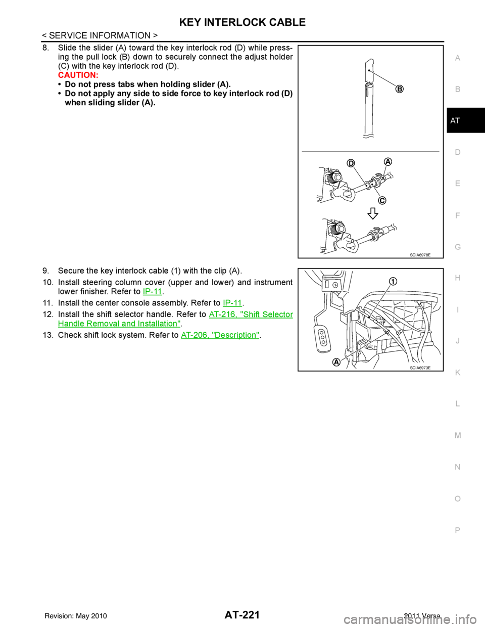
8. Slide the slider (A) toward the key interlock rod (D) while press- ing the pull lock (B) down to securely connect the adjust holder
(C) with the key interlock rod (D).
CAUTION:
• Do not press tabs when holding slider (A).
• Do not apply any side to side force to key interlock rod (D)when sliding slider (A).
9. Secure the key interlock cable (1) with the clip (A).
10. Install steering column cover (upper and lower) and instrument lower finisher. Refer to IP-11
.
11. Install the center console assembly. Refer to IP-11
.
12. Install the shift selector handle. Refer to AT-216, "
Shift Selector
Handle Removal and Installation".
13. Check shift lock system. Refer to AT-206, "
Description".
SCIA6978E
SCIA6973E
Revision: May 2010 2011 Versa
Page 433 of 3787
![NISSAN TIIDA 2011 Service Repair Manual AV-36
< SERVICE INFORMATION >[AUDIO WITHOUT NAVIGATION]
TELEPHONE
tooth cellular telephones may not be recognized by t
he Bluetooth control unit. When a cellular telephone or
the Bluetooth control uni](/manual-img/5/57396/w960_57396-432.png "NISSAN TIIDA 2011 Service Repair Manual AV-36
< SERVICE INFORMATION >[AUDIO WITHOUT NAVIGATION]
TELEPHONE
tooth cellular telephones may not be recognized by t
he Bluetooth control unit. When a cellular telephone or
the Bluetooth control uni")
AV-36
< SERVICE INFORMATION >[AUDIO WITHOUT NAVIGATION]
TELEPHONE
tooth cellular telephones may not be recognized by t
he Bluetooth control unit. When a cellular telephone or
the Bluetooth control unit is replaced, the telephone mu st be paired with the Bluetooth control unit. Different
cellular telephones may have different pairing procedures. Refer to the cellular telephone operating manual.
Bluetooth Telephone System Diagram
Bluetooth Control Unit
When the ignition switch is turned to ACC or ON, the Bluetooth control unit will power up. During power up, the
Bluetooth control unit is initialized and performs various self checks. Initialization may take up to 10 seconds. If
a phone is present in the vehicle and paired with the Bluetooth control unit, NISSAN Voice Recognition will
then become active. Bluetooth telephone functions can be turned off using the NISSAN Voice Recognition
system. For Bluetooth contro l unit location, refer to AV-35, "
Component Parts and Harness Connector Loca-
tion".
Steering Wheel Audio Control Switches
When buttons on the steering wheel audio control switch are pushed, the resistance in steering wheel audio
control switch circuit changes depending on which button is pushed. The Bluetooth control module uses this
signal to perform various functions while navigating through the voice recognition system.
The following functions can be performed using the steering wheel audio control switch:
• Initiate Self Diagnosis of the Bluetooth telephone system
• Start a voice recognition session
• Answer and end telephone calls
• Adjust the volume of calls
• Record memos
Volume Switch
Call volume can be adjusted using the audio unit volume switch.
Bluetooth Microphone
The Bluetooth microphone is located in the roof console assembly. The Bluetooth microphone sends a signal
to the Bluetooth control unit. The Bluetooth microphone c an be actively tested during self-diagnosis. For Blue-
tooth microphone location, refer to AV-35, "
Component Parts and Harness Connector Location".
Audio Unit
The audio unit receives signals from the Bluetooth control unit and sends audio signals to the speakers.
AWNIA2074GB
Revision: May 2010 2011 Versa
Page 446 of 3787
![NISSAN TIIDA 2011 Service Repair Manual TELEPHONEAV-49
< SERVICE INFORMATION > [AUDIO WITHOUT NAVIGATION]
C
D
E
F
G H
I
J
L
M A
B
AV
N
O P
BLUETOOTH MICROPHONE
Removal
1. Remove over-head console assembly, roof finisher. Refer to EI-50.
2.](/manual-img/5/57396/w960_57396-445.png "NISSAN TIIDA 2011 Service Repair Manual TELEPHONEAV-49
< SERVICE INFORMATION > [AUDIO WITHOUT NAVIGATION]
C
D
E
F
G H
I
J
L
M A
B
AV
N
O P
BLUETOOTH MICROPHONE
Removal
1. Remove over-head console assembly, roof finisher. Refer to EI-50.
2.")
TELEPHONEAV-49
< SERVICE INFORMATION > [AUDIO WITHOUT NAVIGATION]
C
D
E
F
G H
I
J
L
M A
B
AV
N
O P
BLUETOOTH MICROPHONE
Removal
1. Remove over-head console assembly, roof finisher. Refer to EI-50.
2. Remove the Bluetooth microphone.
Installation
Installation is in the reverse order of removal.
Revision: May 2010 2011 Versa
Page 475 of 3787
![NISSAN TIIDA 2011 Service Repair Manual AV-78
< SERVICE INFORMATION >[AUDIO WITH NAVIGATION]
TELEPHONE
When a cellular telephone or the Bluetooth control uni
t is replaced, the telephone must be paired with the
Bluetooth control unit. Diffe](/manual-img/5/57396/w960_57396-474.png "NISSAN TIIDA 2011 Service Repair Manual AV-78
< SERVICE INFORMATION >[AUDIO WITH NAVIGATION]
TELEPHONE
When a cellular telephone or the Bluetooth control uni
t is replaced, the telephone must be paired with the
Bluetooth control unit. Diffe")
AV-78
< SERVICE INFORMATION >[AUDIO WITH NAVIGATION]
TELEPHONE
When a cellular telephone or the Bluetooth control uni
t is replaced, the telephone must be paired with the
Bluetooth control unit. Different cellular telephones may have different pairing procedures. Refer to the cellular
telephone operating manual.
Bluetooth Telephone System Diagram
Bluetooth Control Unit
When the ignition switch is turned to ACC or ON, the Bluetooth control unit will power up. During power up, the
Bluetooth control unit is initialized and performs various self checks. Initialization may take up to 20 seconds. If
a phone is present in the vehicle and paired with the Bl uetooth control unit, Nissan Voice Recognition will then
become active. Bluetooth telephone functions can be tur ned off using the Nissan Voice Recognition system.
For Bluetooth control unit location, refer to AV-77, "
Component Parts and Harness Connector Location".
Steering Wheel Audio Control Switches
When buttons on the steering wheel audio control switch are pushed, the resistance in steering wheel audio
control switch circuit changes depending on which button is pushed. The Bluetooth control module uses this
signal to perform various functions while navigating through the voice recognition system.
The following functions can be performed using the steering wheel audio control switch:
• Initiate Self Diagnosis of the Bluetooth telephone system
• Start a voice recognition session
• Answer and end telephone calls
• Adjust the volume of calls
Volume Switch
Call volume can be adjusted using the AV control unit volume switch.
Bluetooth Microphone
The Bluetooth microphone is located in the roof console assembly. The Bluetooth microphone sends a signal
to the Bluetooth control unit. The Bluetooth microphone c an be actively tested during self-diagnosis. For Blue-
tooth microphone location, refer to AV-77, "
Component Parts and Harness Connector Location".
AV Control Unit
The AV control unit receives signals from the Bluet ooth control unit and sends audio signals to the speakers.
AWNIA2191GB
Revision: May 2010 2011 Versa
Page 486 of 3787
![NISSAN TIIDA 2011 Service Repair Manual TELEPHONEAV-89
< SERVICE INFORMATION > [AUDIO WITH NAVIGATION]
C
D
E
F
G H
I
J
L
M A
B
AV
N
O P
BLUETOOTH MICROPHONE
Removal
1. Remove over-head console assembly, roof finisher. Refer to EI-50.
2. Re](/manual-img/5/57396/w960_57396-485.png "NISSAN TIIDA 2011 Service Repair Manual TELEPHONEAV-89
< SERVICE INFORMATION > [AUDIO WITH NAVIGATION]
C
D
E
F
G H
I
J
L
M A
B
AV
N
O P
BLUETOOTH MICROPHONE
Removal
1. Remove over-head console assembly, roof finisher. Refer to EI-50.
2. Re")
TELEPHONEAV-89
< SERVICE INFORMATION > [AUDIO WITH NAVIGATION]
C
D
E
F
G H
I
J
L
M A
B
AV
N
O P
BLUETOOTH MICROPHONE
Removal
1. Remove over-head console assembly, roof finisher. Refer to EI-50.
2. Remove the Bluetooth microphone.
Installation
Installation is in the reverse order of removal.
Revision: May 2010 2011 Versa
Page 519 of 3787

SQUEAK AND RATTLE TROUBLE DIAGNOSESBL-9
< SERVICE INFORMATION >
C
DE
F
G H
J
K L
M A
B
BL
N
O P
SILICONE GREASE
Used instead of UHMW tape that will be visible or not fit.
Note: Will only last a few months.
SILICONE SPRAY
Use when grease cannot be applied.
DUCT TAPE
Use to eliminate movement.
CONFIRM THE REPAIR
Confirm that the cause of a noise is repaired by test driving the vehicle. Operate the vehicle under the same
conditions as when the noise originally occurred. Refer to the notes on the Diagnostic Worksheet.
Generic Squeak and Rattle TroubleshootingINFOID:0000000005929274
Refer to Table of Contents for specific component removal and installation information.
INSTRUMENT PANEL
Most incidents are caused by contact and movement between:
1. The cluster lid A and instrument panel
2. Acrylic lens and combination meter housing
3. Instrument panel to front pillar garnish
4. Instrument panel to windshield
5. Instrument panel mounting pins
6. Wiring harnesses behind the combination meter
7. A/C defroster duct and duct joint
These incidents can usually be located by tapping or moving the components to duplicate the noise or by
pressing on the components while driving to stop the noi se. Most of these incidents can be repaired by apply-
ing felt cloth tape or silicone spray (in hard to reach areas). Urethane pads can be used to insulate wiring har-
ness.
CAUTION:
Do not use silicone spray to isolate a squeak or ra ttle. If you saturate the area with silicone, you will
not be able to recheck the repair.
CENTER CONSOLE
Components to pay attention to include:
1. Shift selector cover to finisher
2. A/C control unit and cluster lid C
3. Wiring harnesses behind audio and A/C control unit
The instrument panel repair and isolation pr ocedures also apply to the center console.
DOORS
Pay attention to the:
1. Finisher and inner panel making a slapping noise
2. Inside handle escutcheon to door finisher
3. Wiring harnesses tapping
4. Door striker out of alignment causing a popping noise on starts and stops
Tapping or moving the components or pressing on them while driving to duplicate the conditions can isolate
many of these incidents. You can usually insulate the ar eas with felt cloth tape or insulator foam blocks from
the NISSAN Squeak and Rattle Kit (J-43980) to repair the noise.
TRUNK
Trunk noises are often caused by a loose jack or loose items put into the trunk by the owner.
In addition look for:
1. Trunk lid bumpers out of adjustment
2. Trunk lid striker out of adjustment
3. The trunk lid torsion bars knocking together
4. A loose license plate or bracket
Revision: May 2010 2011 Versa