2011 NISSAN TIIDA Body lock
[x] Cancel search: Body lockPage 566 of 3787

BL-56
< SERVICE INFORMATION >
POWER DOOR LOCK SYSTEM
1. Disconnect BCM connector M18.
2. Check continuity between BCM connector (A) M18 terminals 7,8 and front door lock assembly LH (key cylinder switch) connec-
tor (B) D14 terminals 5, 6 and body ground.
OK or NG
OK >> Front door lock assembly LH (key cylinder switch) circuit is OK.
NG >> Repair or replace harness.
Passenger Select Unlock Relay Circuit Inspection (With Intelligent Key)INFOID:0000000005929301
1.CHECK PASSENGER SELECT UNLOCK RELAY CIRCUIT
NOTE:
Passenger select unlock relay must remain connected during this step.
1. Turn ignition switch OFF.
2. Disconnect BCM and inoperative rear door lock actuator.
3. Check continuity between BCM connector (A) M20 terminal 65 and rear door lock actuator LH connector (B) D205 terminal 3 or
rear door lock actuator RH connector (C) D305 Terminal 3.
4. Check continuity between BCM connector (A) M20 terminal 65 and body ground.
OK or NG
OK >> GO TO 4
NG >> GO TO 2
2.CHECK PASSENGER SELECT UNLOCK RELAY INPUT
1. Disconnect passenger select unlock relay.
2. Check continuity between BCM connector (A) M20 terminal 65 and passenger select unlock relay connector (B) M2 terminal 3.
3. Check continuity between BCM connector (A) M20 terminal 65 and body ground.
OK or NG
OK >> GO TO 3
NG >> Repair or replace harness between BCM and relay.
3.CHECK PASSENGER SELECT UNLOCK RELAY OUTPUT
Connector Terminal Connector Terminal Continuity
A: M18 7
B: D14 5Y
es
86Y es
7G ro u nd N o
8G ro u nd N o
AWKIA1669ZZ
65 - 3 : Continuity should exist.
65 - Ground : Continuity should not exist.
WIIA1164E
65 - 3 : Continuity should exist.
65 - Ground : Continuity should not exist.
WIIA1165E
Revision: May 2010 2011 Versa
Page 569 of 3787
![NISSAN TIIDA 2011 Service Repair Manual REMOTE KEYLESS ENTRY SYSTEMBL-59
< SERVICE INFORMATION >
C
DE
F
G H
J
K L
M A
B
BL
N
O P
• through 10A fuse [No. 14, located in the fuse block (J/B)]
• through key switch terminals 2 and 1
• to](/manual-img/5/57396/w960_57396-568.png "NISSAN TIIDA 2011 Service Repair Manual REMOTE KEYLESS ENTRY SYSTEMBL-59
< SERVICE INFORMATION >
C
DE
F
G H
J
K L
M A
B
BL
N
O P
• through 10A fuse [No. 14, located in the fuse block (J/B)]
• through key switch terminals 2 and 1
• to")
REMOTE KEYLESS ENTRY SYSTEMBL-59
< SERVICE INFORMATION >
C
DE
F
G H
J
K L
M A
B
BL
N
O P
• through 10A fuse [No. 14, located in the fuse block (J/B)]
• through key switch terminals 2 and 1
• to BCM terminal 37.
When the ignition switch is ACC or ON, power is supplied
• through 10A fuse [No. 20, located in the fuse block (J/B)]
• to BCM terminal 11.
Ground is supplied
• to BCM terminal 67
• through body grounds M57 and M61.
When the front door switch LH is ON (door is OPEN), ground is supplied
• to BCM terminal 47
• through front door switch LH terminal 2
• through front door switch LH case ground.
When the front door switch RH is ON (door is OPEN), ground is supplied
• to BCM terminal 12
• through front door switch RH terminal 2
• through front door switch RH case ground.
When the rear door switch LH is ON (door is OPEN), ground is supplied
• to BCM terminal 48
• through rear door switch LH terminal 1
• through rear door switch LH case ground.
When the rear door switch RH is ON (door is OPEN), ground is supplied
• to BCM meter terminal 13
• through rear door switch RH terminal 1
• through rear door switch RH case ground.
When the back door lock assembly (back door switch) (hat chback) is ON (back door is OPEN), ground is sup-
plied
• to BCM terminal 43
• through back door lock assembly (back door switch) terminals 3 and 4
• through body grounds B117, B132 and D402.
Keyfob signal is inputted to BCM from remote keyless entry receiver.
The remote keyless entry system controls operation of the
• power door lock
• hazard reminder
• auto door lock
• panic alarm
• room lamp
OPERATED PROCEDURE
Power Door Lock Operation
BCM receives a LOCK signal from keyfob. BCM locks all doors with input of LOCK signal from keyfob.
BCM receives a UNLOCK signal from keyfob. BCM unlocks all doors with input of UNLOCK signal from key-
fob.
Hazard and Horn Reminder
When the doors are locked or unlocked by keyfob, power is supplied to sound horn and flash hazard warning
lamps as follows
• LOCK operation: 3 or 4 mode (lamps flash twice)
• UNLOCK operation: 2 or 4 mode (lamps flash once)
• Horn sounds once with LOCK function when this feature is set ON.
The hazard reminder has modes 1, 2, 3 or 4. The hor n reminder can be turned ON/OFF with any LOCK mode.
Operating function of hazard reminder
Hazard and horn reminders do not operate if any door switch is ON (any door is OPEN).
How to change hazard and horn reminder modes
Mode 1Mode 2Mode 3 Mode 4
Keyfob operation Lock Unlock Lock Unlock Lock Unlock Lock Unlock
Hazard warning lamp
flash — — — Twice Once — Once Twice
Horn sound (ON/OFF) ON: once — O N: once — ON: once — ON: once —
Revision: May 2010 2011 Versa
Page 599 of 3787

INTELLIGENT KEY SYSTEMBL-89
< SERVICE INFORMATION >
C
DE
F
G H
J
K L
M A
B
BL
N
O P
Operation Description
• When the Intelligent Key unit detects that each request sw
itch is pressed, it starts the outside key antenna
and inside key antenna corresponding to the pressed request switch and sends the request signal to the
Intelligent Key. And then, make sure that the Intelligent Key is near door.
• If the Intelligent Key is within the outside key antenna detection area, it receives the request signal and sends the key ID signal to the Intelligent Key unit.
• Intelligent Key unit receives the key ID signal and compares it with the registered key ID.
• If the key ID check result is OK, the Intelligent Ke y unit sends the door lock/unlock request signal to BCM
(Body control module) via CAN communication line.
• Intelligent Key unit sends the door lock/unlock signal and sounds Intelligent Key warning buzzer (lock: 2 times, unlock: 1 time) at the same time.
• When BCM receives the door lock/unlock signal, it oper ates door lock actuator and flashes the hazard warn-
ing lamp (lock: 2 times, unlock: 1 time) at the same time as reminder.
Operation Condition
If the following conditions are not satisfied, door lock/unlock operations are not performed even if the request
switch is operated.
*: Even with a registered Intelligent Key remaining inside the vehicle, door locks can be unlocked from outside of the vehicle with a spare
Intelligent Key as long as Key IDs are different.
Outside Key Antenna Detection Area
The outside key antenna detection area of door lock/unloc k function is in the range of approximately 80 cm
(31.50 in) surrounding the request switch (driver side, passenger side and back door or trunk area).
Hazard and Buzzer Reminder
When all doors and trunk (sedan) are locked or unlocked by each request switch, Intelligent Key\
unit sends
hazard request signal to BCM via CAN communication line.
BCM flashes hazard warning lamps as a reminder and Intelligent Key unit sounds Intelligent Key warning
buzzer(s) as a reminder.
Operating function of hazard and buzzer reminder
* : Sedan only
Auto Door Lock Function
When all doors and trunk (sedan) are locked, ignition knob sw itch is OFF (when ignition switch is not pressed)
and key switch is OFF (when mechanical key is out of ignition key cylinder), all doors are unlocked with each
request switch.
When Intelligent Key unit does not receive the following signals within 1 minute, all doors are locked.
• Door switch is ON (door is opened)
• Trunk lamp switch (sedan) is ON (trunk is opened)
• Door lock signal from Intelligent Key button
• Ignition knob switch is ON (ignition switch is pressed)
• Key switch is ON (mechanical key is inserted in ignition key cylinder)
Auto door lock mode can be changed by “AUTO RELOCK TIMER” mode in “WORK SUPPORT”. Refer to BL-
117, "CONSULT-III Application Item".
List of Operation Related Parts
Parts marked with × are the parts related to operation.
Each request switch operation Operation conditionOperation
Lock operation • All doors and trunk (sedan) are closed
• Intelligent Key is outside of the vehicle
• Intelligent Key is within outside key antenna detection area All doors lock
Unlock Operation • All doors and trunk (sedan) are closed
• Intelligent Key is outside of the vehicle
• Intelligent Key is within outside key antenna detection area*
All doors unlock
Request switch operation
Hazard warning lamp flashIntelligent Key warning buzzer (front door LH)
Intelligent Key warning buzzer (trunk)*
Unlock Once Once
Lock Twice Twice
Revision: May 2010 2011 Versa
Page 683 of 3787
BACK DOOR LOCKBL-173
< SERVICE INFORMATION >
C
DE
F
G H
J
K L
M A
B
BL
N
O P
BACK DOOR LOCK
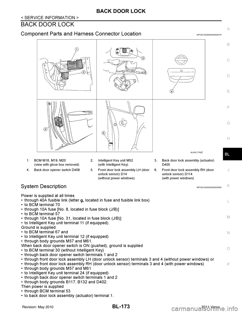
Component Parts and Har ness Connector LocationINFOID:0000000005929379
System DescriptionINFOID:0000000005929380
Power is supplied at all times
• through 40A fusible link (letter g, located in fuse and fusible link box)
• to BCM terminal 70
• through 10A fuse [No. 8, located in fuse block (J/B)]
• to BCM terminal 57
• through 10A fuse [No. 31, located in fuse block (J/B)]
• to Intelligent Key unit terminal 11 (if equipped).
Ground is supplied
• to BCM terminal 67 and
• to Intelligent Key unit terminal 12 (if equipped)
• through body grounds M57 and M61.
When back door opener switch is ON (pushed), ground is supplied
• to BCM terminal 30 (without Intelligent Key)
• through back door opener switch terminals 1 and 2
• through front door lock assembly LH (door unlock sensor) terminals 3 and 4 (without power windows) or
• through front door lock assembly RH (door unlock sensor) terminals 3 and 4 (with power windows)
• through body grounds M57 and M61
• to Intelligent Key unit terminal 24 (if equipped)
• through back door opener switch terminals 1 and 2
• through body grounds B117, B132 and D402.
Then power is supplied
• through BCM terminal 53
• to back door lock assembly (actuator) terminal 1.
ALKIA1776ZZ
1. BCM M18, M19, M20
(view with glove box removed) 2. Intelligent Key unit M52
(with Intelligent Key) 3. Back door lock assembly (actuator)
D405
4. Back door opener switch D408 5. Front door lock assembly LH (door unlock sensor) D14
(without power windows)6. Front door lock assembly RH (door
unlock sensor) D114
(with power windows)
Revision: May 2010 2011 Versa
Page 684 of 3787
BL-174
< SERVICE INFORMATION >
BACK DOOR LOCK
Ground is supplied
• to back door lock assembly (actuator) terminal 2
• through body grounds B117, B132 and D402.
Then BCM operates back door lock assembly (actuator).
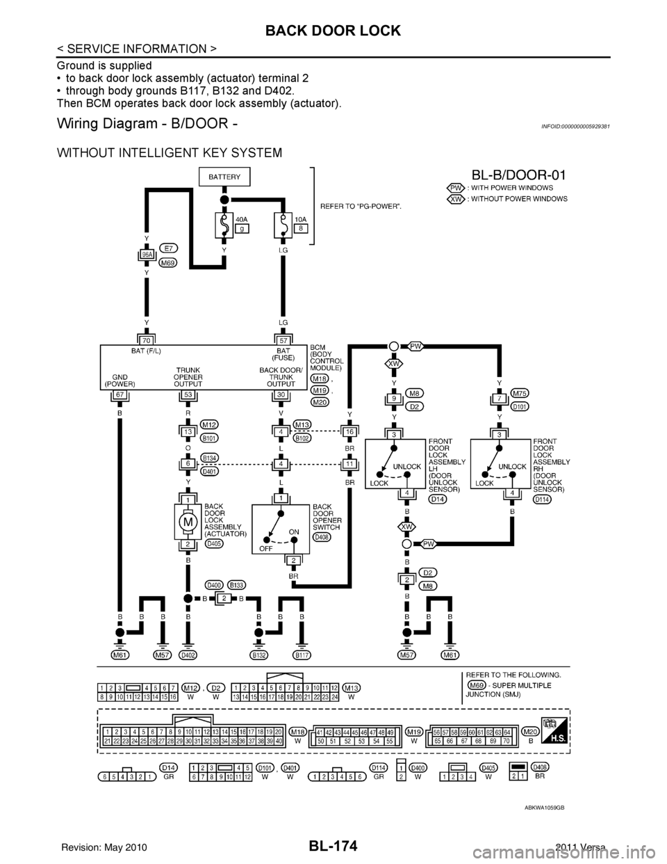
Wiring Diagram - B/DOOR -INFOID:0000000005929381
WITHOUT INTELLIGENT KEY SYSTEM
ABKWA1059GB
Revision: May 20102011 Versa
Page 706 of 3787
BL-196
< SERVICE INFORMATION >
TRUNK LID
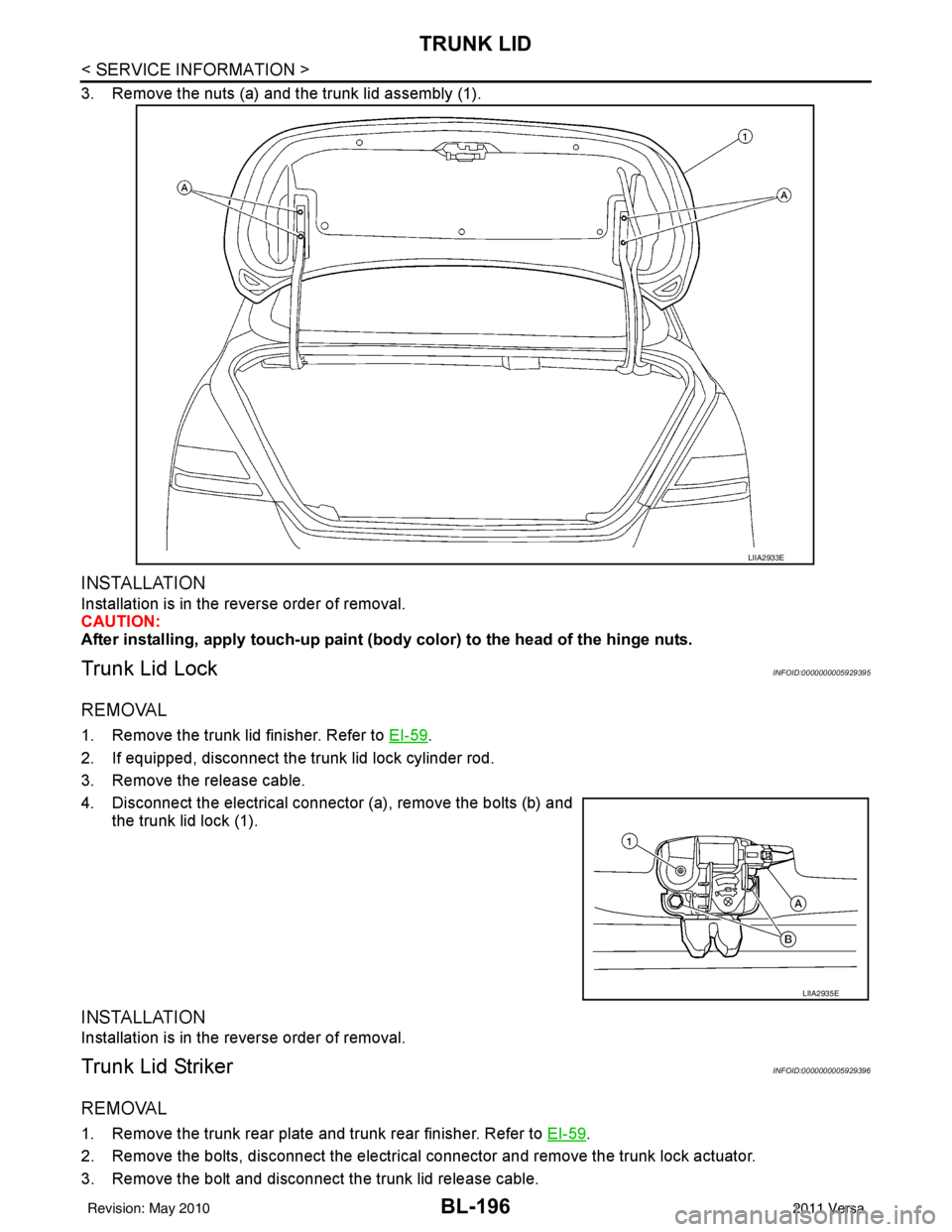
3. Remove the nuts (a) and the trunk lid assembly (1).
INSTALLATION
Installation is in the reverse order of removal.
CAUTION:
After installing, apply touch-up paint (body color) to the head of the hinge nuts.
Trunk Lid LockINFOID:0000000005929395
REMOVAL
1. Remove the trunk lid finisher. Refer to EI-59.
2. If equipped, disconnect the trunk lid lock cylinder rod.
3. Remove the release cable.
4. Disconnect the electrical connector (a), remove the bolts (b) and the trunk lid lock (1).
INSTALLATION
Installation is in the reverse order of removal.
Trunk Lid StrikerINFOID:0000000005929396
REMOVAL
1. Remove the trunk rear plate and trunk rear finisher. Refer to EI-59.
2. Remove the bolts, disconnect the electrical connector and remove the trunk lock actuator.
3. Remove the bolt and disconnect the trunk lid release cable.
LIIA2933E
LIIA2935E
Revision: May 2010 2011 Versa
Page 708 of 3787
BL-198
< SERVICE INFORMATION >
TRUNK LID OPENER
TRUNK LID OPENER
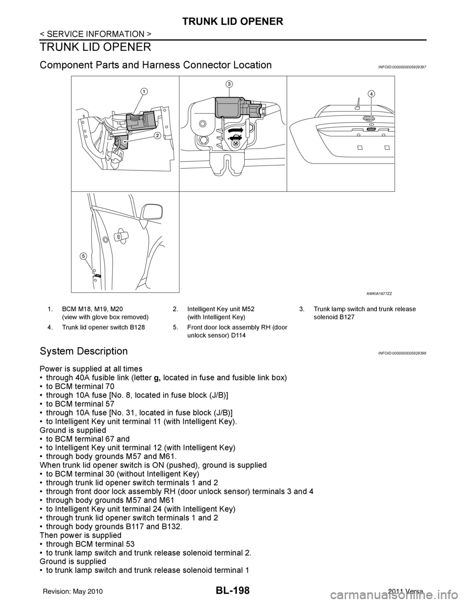
Component Parts and Harness Connector LocationINFOID:0000000005929397
System DescriptionINFOID:0000000005929398
Power is supplied at all times
• through 40A fusible link (letter g, located in fuse and fusible link box)
• to BCM terminal 70
• through 10A fuse [No. 8, located in fuse block (J/B)]
• to BCM terminal 57
• through 10A fuse [No. 31, located in fuse block (J/B)]
• to Intelligent Key unit terminal 11 (with Intelligent Key).
Ground is supplied
• to BCM terminal 67 and
• to Intelligent Key unit terminal 12 (with Intelligent Key)
• through body grounds M57 and M61.
When trunk lid opener switch is ON (pushed), ground is supplied
• to BCM terminal 30 (without Intelligent Key)
• through trunk lid opener switch terminals 1 and 2
• through front door lock assembly RH (door unlock sensor) terminals 3 and 4
• through body grounds M57 and M61
• to Intelligent Key unit terminal 24 (with Intelligent Key)
• through trunk lid opener switch terminals 1 and 2
• through body grounds B117 and B132.
Then power is supplied
• through BCM terminal 53
• to trunk lamp switch and trunk release solenoid terminal 2.
Ground is supplied
• to trunk lamp switch and trunk release solenoid terminal 1
AWKIA1677ZZ
1. BCM M18, M19, M20
(view with glove box removed) 2. Intelligent Key unit M52
(with Intelligent Key) 3. Trunk lamp switch and trunk release
solenoid B127
4. Trunk lid opener switch B128 5. Front door lock assembly RH (door unlock sensor) D114
Revision: May 2010 2011 Versa
Page 729 of 3787

VEHICLE SECURITY (THEFT WARNING) SYSTEMBL-219
< SERVICE INFORMATION >
C
DE
F
G H
J
K L
M A
B
BL
N
O P
• to combination meter terminal 27 (security indicator lamp)
• through 40A fusible link (letter g, located in the fuse and fusible link box)
• to BCM terminal 70
• through 10A fuse [No. 8, located in the fuse block (J/B)]
• to BCM terminal 57
• through 10A fuse (No. 28, located in the fuse and fusible link box)
• to horn relay terminal 2
• through 15A fuse (No. 52, located in the IPDM E/R)
• to IPDM E/R internal CPU.
• through 20A fuse (No. 53, located in the IPDM E/R)
• to IPDM E/R internal CPU.
With the ignition switch in the ACC or ON position, power is supplied• through 10A fuse [No. 20, located in the fuse block (J/B)]
• to BCM terminal 11.
With the ignition switch in the ON or START position, power is supplied• through 10A fuse [No. 6, located in the fuse block (J/B)]
• to BCM terminal 38.
Ground is supplied• to BCM terminal 67
• through body grounds M57 and M61.
INITIAL CONDITION TO ACTIVATE THE SYSTEM
The operation of the vehicle security system is controlled by the doors and trunk (sedan).
To activate the vehicle security system, BCM must receive signals indicating the ignition switch is OFF, doors
and trunk (sedan) are closed and locked.
When a door or trunk (sedan) is open, BCM terminal 12, 13, 42, 43, 47 or 48 receives a ground signal from
each door or trunk switch. In addition to BCM, when back door is open, the Intelligent Key unit terminal 23
receives a ground signal from back door or trunk (sedan) through BCM terminal 30.
When front door LH is unlocked, BCM terminal 46 receives a signal from terminal 6 of main power window and
door lock/unlock switch.
When front door RH is unlocked, BCM terminal 46 receives a signal from terminal 2 of power window and door
lock/unlock switch RH.
VEHICLE SECURITY SYSTEM ALARM OPERATION
The vehicle security system is triggered by
• Opening a door without using the key, keyfob or Intelligent Key.
• Opening trunk without using the key, keyfob or Intelligent Key (sedan).
The vehicle security system will be triggered once the system is in armed phase,
• when BCM receives a ground signal at terminals 12, 13, 47, 48 (front or rear door switch), terminal 42 (sedan, trunk switch) or terminal 43 (hatchback, back door switch).
When the vehicle security system is triggered, ground is supplied intermittently
• from IPDM E/R terminal 45
• to horn relay terminal 1.
The headlamps flash and the hor n sounds intermittently.
The alarm automatically turns off after 50 seconds, but will reactivate if the vehicle is tampered with again.
VEHICLE SECURITY SYSTEM DEACTIVATION
To deactivate the vehicle security system, a door or trunk (sedan) must be unlocked with the key, keyfob or
Intelligent Key.
When the key is used to unlock the driver door, BCM terminal 7 receives signal
• from terminal 3 of the front door lock assembly LH (key cylinder switch).
When the key is used to open the trunk (sedan), BCM terminal 41 receives signal
• from terminal 1 of the trunk key cylinder switch.
When the BCM receives an unlock signal from keyfob, Intelligent Key, front door key cylinder switch LH or
trunk key cylinder switch (sedan), the vehicle security system is deactivated (Disarmed phase).
PANIC ALARM OPERATION
Intelligent Key and remote keyless entry system may or may not operate vehicle security system (horn and
headlamps) as required.
When the vehicle security system is triggered, ground is supplied intermittently
Revision: May 2010 2011 Versa