2011 NISSAN TIIDA Body lock
[x] Cancel search: Body lockPage 850 of 3787
PRECAUTIONSBR-3
< SERVICE INFORMATION >
C
DE
G H
I
J
K L
M A
B
BR
N
O P
5. When the repair work is completed, return the ignition switch to the ″LOCK ″ position before connecting
the battery cables. (At this time, the steering lock mechanism will engage.)
6. Perform a self-diagnosis check of al l control units using CONSULT-III.
Precaution for Brake SystemINFOID:0000000005928387
• Refill using recommended brake fluid. Refer to MA-14.
• Never reuse drained brake fluid.
• Be careful not to splash brake fluid on painted surface of body. If brake fluid is splashed on painted surfaces of body immediately wipe it off with cloth and then wash it away with water.
• To clean or wash all parts of master cylinder, disc brake caliper and wheel cylinder, use new brake fluid.
• Never use mineral oils such as gasoline or kerosene. They will ruin rubber parts of the hydraulic system.
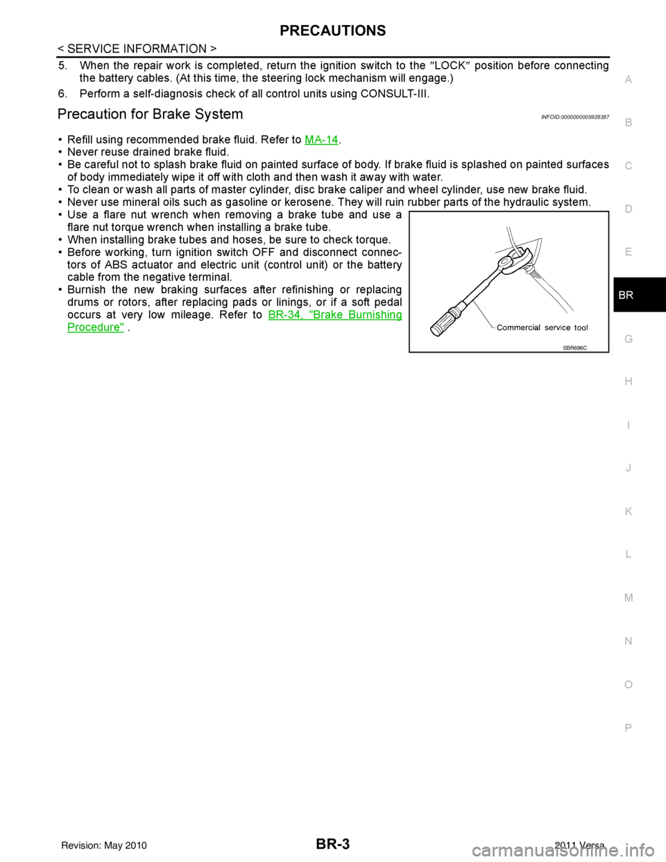
• Use a flare nut wrench when removing a brake tube and use a flare nut torque wrench when installing a brake tube.
• When installing brake tubes and hoses, be sure to check torque.
• Before working, turn igniti on switch OFF and disconnect connec-
tors of ABS actuator and electric unit (control unit) or the battery
cable from the negative terminal.
• Burnish the new braking surfaces after refinishing or replacing drums or rotors, after replacing p ads or linings, or if a soft pedal
occurs at very low mileage. Refer to BR-34, "
Brake Burnishing
Procedure" .
SBR686C
Revision: May 2010 2011 Versa
Page 859 of 3787
BR-12
< SERVICE INFORMATION >
BRAKE TUBE AND HOSE
• All tubes and hoses must be free from excessive bending, twisting and pulling.
• Make sure there is no interference with other part s when turning steering both clockwise and coun-
terclockwise.
• Brake tubes and hoses are an important safety part. Always disassemble the parts and retighten
their fittings, if a brake fluid leak is detected. Replace applicable part with a new one, if damaged part
is detected.
• Be careful not to splash brake fluid on painted areas; it may cause paint damage. If brake fluid is
splashed on painted surfaces of body , immediately wipe them with cloth and then wash it away with
water.
• Do not bend or twist brake hose sharply, or strongly pull it.
• When removing components, cover brake line connect ions so that dirt, dust, or other foreign mat-
ters do not get in.
• Refill using recommended brake fluid. Refer to MA-14, "
Fluids and Lubricants".
• Never reuse drained brake fluid.
Front Brake Tube and HoseINFOID:0000000005928397
REMOVAL
1. Drain brake fluid. Refer to BR-9, "Drain and Refill".
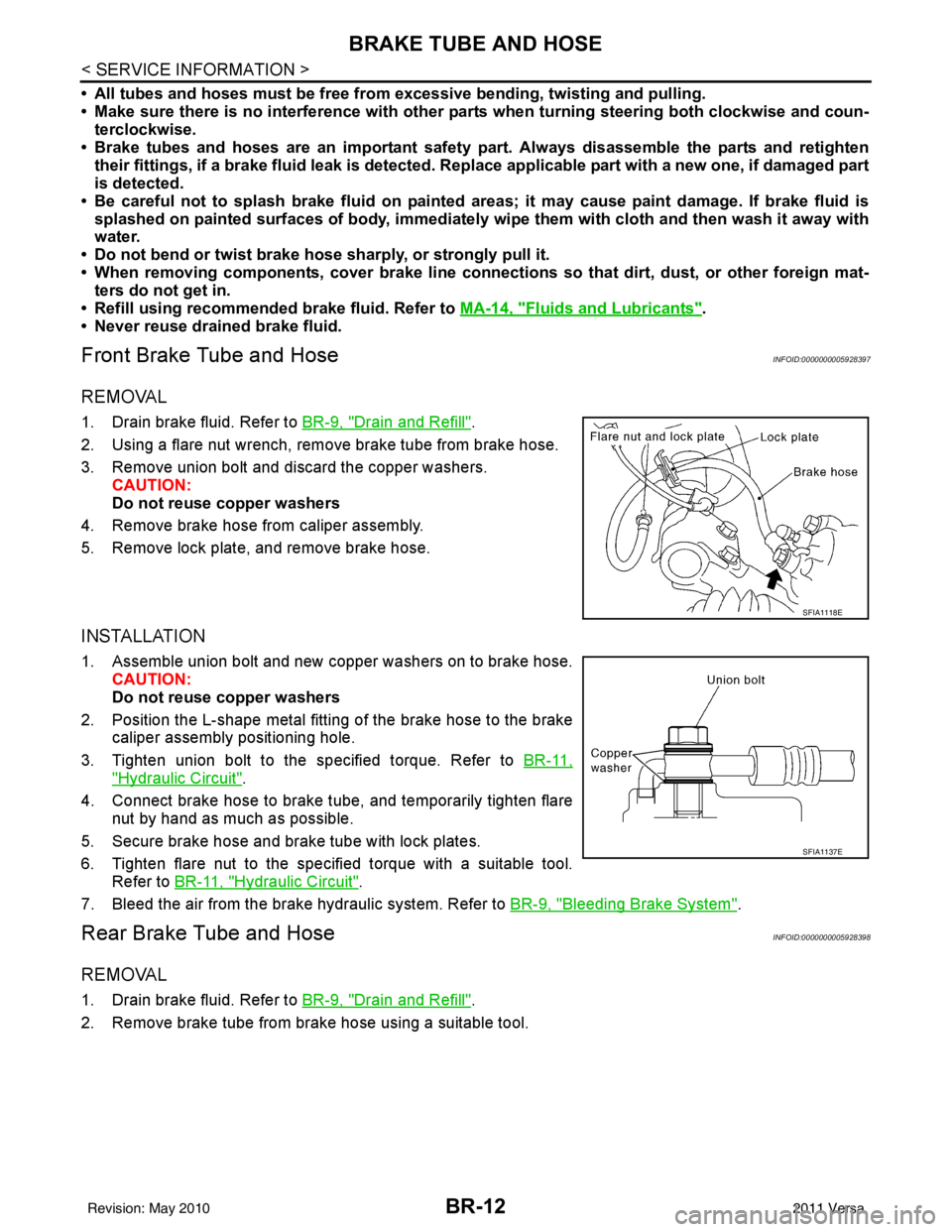
2. Using a flare nut wrench, remove brake tube from brake hose.
3. Remove union bolt and discard the copper washers. CAUTION:
Do not reuse copper washers
4. Remove brake hose from caliper assembly.
5. Remove lock plate, and remove brake hose.
INSTALLATION
1. Assemble union bolt and new copper washers on to brake hose. CAUTION:
Do not reuse copper washers
2. Position the L-shape metal fitting of the brake hose to the brake caliper assembly positioning hole.
3. Tighten union bolt to the specified torque. Refer to BR-11,
"Hydraulic Circuit".
4. Connect brake hose to brake tube, and temporarily tighten flare nut by hand as much as possible.
5. Secure brake hose and brake tube with lock plates.
6. Tighten flare nut to the specified torque with a suitable tool. Refer to BR-11, "
Hydraulic Circuit".
7. Bleed the air from the brake hydraulic system. Refer to BR-9, "
Bleeding Brake System".
Rear Brake Tube and HoseINFOID:0000000005928398
REMOVAL
1. Drain brake fluid. Refer to BR-9, "Drain and Refill".
2. Remove brake tube from brake hose using a suitable tool.
SFIA1118E
SFIA1137E
Revision: May 2010 2011 Versa
Page 865 of 3787
BR-18
< SERVICE INFORMATION >
BRAKE MASTER CYLINDER
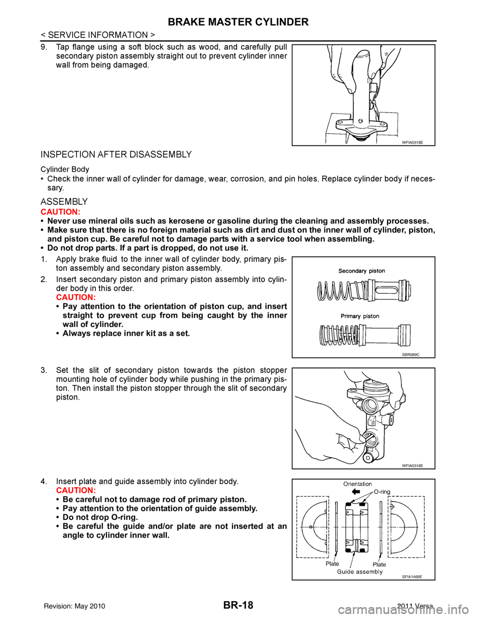
9. Tap flange using a soft block such as wood, and carefully pullsecondary piston assembly straight out to prevent cylinder inner
wall from being damaged.
INSPECTION AFTER DISASSEMBLY
Cylinder Body
• Check the inner wall of cylinder for damage, wear, corrosion, and pin holes. Replace cylinder body if neces-sary.
ASSEMBLY
CAUTION:
• Never use mineral oils such as kerosene or g asoline during the cleaning and assembly processes.
• Make sure that there is no foreign material such as dirt and dust on the inner wall of cylinder, piston,
and piston cup. Be careful not to damage parts with a service tool when assembling.
• Do not drop parts. If a part is dropped, do not use it.
1. Apply brake fluid to the inner wall of cylinder body, primary pis- ton assembly and secondary piston assembly.
2. Insert secondary piston and primary piston assembly into cylin- der body in this order.
CAUTION:
• Pay attention to the orientation of piston cup, and insert
straight to prevent cup from being caught by the inner
wall of cylinder.
• Always replace inner kit as a set.
3. Set the slit of secondary piston towards the piston stopper mounting hole of cylinder body while pushing in the primary pis-
ton. Then install the piston stopper through the slit of secondary
piston.
4. Insert plate and guide assembly into cylinder body. CAUTION:
• Be careful not to damage rod of primary piston.
• Pay attention to the orientation of guide assembly.
• Do not drop O-ring.
• Be careful the guide and/or plate are not inserted at an
angle to cylinder inner wall.
WFIA0518E
SBR089C
WFIA0516E
SFIA1469E
Revision: May 2010 2011 Versa
Page 878 of 3787
FRONT DISC BRAKEBR-31
< SERVICE INFORMATION >
C
DE
G H
I
J
K L
M A
B
BR
N
O P
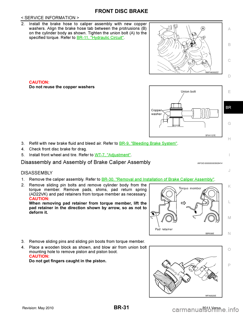
2. Install the brake hose to caliper assembly with new copper washers. Align the brake hose tab between the protrusions (B)
on the cylinder body as shown. Tighten the union bolt (A) to the
specified torque. Refer to BR-11, "
Hydraulic Circuit".
CAUTION:
Do not reuse the copper washers
3. Refill with new brake fluid and bleed air. Refer to BR-9, "
Bleeding Brake System".
4. Check front disc brake for drag.
5. Install front wheel and tire. Refer to WT-7, "
Adjustment".
Disassembly and Assembly of Brake Caliper AssemblyINFOID:0000000005928414
DISASSEMBLY
1. Remove the caliper assembly. Refer to BR-30, "Removal and Installation of Brake Caliper Assembly".
2. Remove sliding pin bolts and remove cylinder body from the torque member. Remove pads, shims, pad return spring
(AD22VK) and pad retainers from torque member as necessary.
CAUTION:
When removing pad retainer from torque member, lift the
pad retainer in the direction shown by arrow, so as not to
deform it.
3. Remove sliding pins and sliding pin boots from torque member.
4. Place a wooden block as shown, and blow air from union bolt mounting hole to remove piston and piston boot.
CAUTION:
Do not get fingers caught in the piston.
AWFIA0502ZZ
SFIA1137E
SBR556E
WFIA0525E
Revision: May 2010 2011 Versa
Page 923 of 3787
![NISSAN TIIDA 2011 Service Repair Manual BRC-34
< SERVICE INFORMATION >[ABS]
WHEEL SENSORS
• When installing front wheel senso
r, press rubber grommets of strut bracket and body all the way in
until they get locked, and be careful not to](/manual-img/5/57396/w960_57396-922.png "NISSAN TIIDA 2011 Service Repair Manual BRC-34
< SERVICE INFORMATION >[ABS]
WHEEL SENSORS
• When installing front wheel senso
r, press rubber grommets of strut bracket and body all the way in
until they get locked, and be careful not to")
BRC-34
< SERVICE INFORMATION >[ABS]
WHEEL SENSORS
• When installing front wheel senso
r, press rubber grommets of strut bracket and body all the way in
until they get locked, and be careful not to apply a twist to harness. Harness should not be twisted
after installation. (Install it with harness paint mark on body side grommet facing front of vehicle,
and the strut side grommet facing outside of vehicle.)
REAR WHEEL SENSOR
Removal
CAUTION:
• As much as possible, avoid rotating wheel sensor when removing it . Pull wheel sensors out without
pulling on sensor harness.
• Take care to avoid damaging wheel sensor edges or rotor teeth. Remove wheel sensor first before
removing front or rear wheel hub. This is to avoid damage to wheel sensor wiring and loss of sensor
function.
1. Disconnect the rear wheel sensor connector.
2. Remove the rear wheel sensor.
Installation
Installation is in the reverse order of removal.
CAUTION:
• When installing, make sure there is no foreign material such as iron chips on and in the mounting
hole of the wheel sensor. Make sure no foreign material has been caught in the sensor rotor. Remove
any foreign material and clean the mount.
• When installing rear wheel sensor, press rubber grommets of suspension arm bracket and harness
of side member all the way in until they get locked , and be careful not to apply a twist to harness.
Harness should not be twisted af ter installation. (Aim the paint mark upward of vehicle.)
Revision: May 2010 2011 Versa
Page 928 of 3787
![NISSAN TIIDA 2011 Service Repair Manual PRECAUTIONSBRC-39
< SERVICE INFORMATION > [VDC/TCS/ABS]
C
D
E
G H
I
J
K L
M A
B
BRC
N
O P
5. When the repair work is completed, re-connect both battery cables. With the brake pedal released, turn the](/manual-img/5/57396/w960_57396-927.png "NISSAN TIIDA 2011 Service Repair Manual PRECAUTIONSBRC-39
< SERVICE INFORMATION > [VDC/TCS/ABS]
C
D
E
G H
I
J
K L
M A
B
BRC
N
O P
5. When the repair work is completed, re-connect both battery cables. With the brake pedal released, turn the")
PRECAUTIONSBRC-39
< SERVICE INFORMATION > [VDC/TCS/ABS]
C
D
E
G H
I
J
K L
M A
B
BRC
N
O P
5. When the repair work is completed, re-connect both battery cables. With the brake pedal released, turn the push-button ignition switch from ACC position to ON position, then to LOCK position. (The steering
wheel will lock when the push-button ignition switch is turned to LOCK position.)
6. Perform self-diagnosis check of a ll control units using CONSULT-III.
Precaution for Brake SystemINFOID:0000000005928462
CAUTION:
• Refer to MA-14, "
Fluids and Lubricants" for recommended brake fluid.
• Never reuse drained brake fluid.
• Be careful not to splash brake fluid on painted areas; it may cause paint damage. If brake fluid is
splashed on painted areas, wash it away with water immediately.
• To clean or wash all parts of master cylin der and disc brake caliper, use clean brake fluid.
• Never use mineral oils such as gasoline or kerosen e. They will ruin rubber parts of the hydraulic sys-
tem.
• Use flare nut wrench when removing and installing brake tube.
• If a brake fluid leak is found, the part must be disassembled
without fail. Then it has to be replaced with a new one if a
defect exists.
• Turn the ignition switch OFF and remove the connector of the
ABS actuator and electric unit (con trol unit) or the battery ter-
minal before performing the work.
• Always torque brake lines when installing.
• Burnish the brake contact surf aces after refinishing or replac-
ing rotors, after replacing pads, or if a soft pedal occurs at
very low mileage.
Refer to BR-34, "
Brake Burnishing Procedure".
WARNING:
• Clean brake pads and shoes with a waste cl oth, then wipe with a dust collector.
Precaution for Brake ControlINFOID:0000000005928463
• During ABS operation, the brake pedal may vibrate lightly and a mechanical noise may be heard. This is
normal.
• Just after starting vehicle, the brake pedal may vibrate or a motor operating noise may be heard from engine
compartment. This is a normal status of operation check.
• Stopping distance may be longer than that of vehicles without ABS when vehicle drives on rough, gravel, or snow-covered (fresh, deep snow) roads.
• When an error is indicated by ABS or another warning lamp, collect all necessary information from customer (what symptoms are present under what conditions) and check for simple causes before starting diagnosis.
Besides electrical system inspection, check boos ter operation, brake fluid level, and fluid leaks.
• If incorrect tire sizes or types are installed on the vehicle or brake pads are not Genuine NISSAN parts, stop-
ping distance or steering stability may deteriorate.
• If there is a radio, antenna or related wiring near control module, ABS function may have a malfunction or
error.
• If aftermarket parts (car stereo, CD player, etc.) have been installed, check for incidents such as harness pinches, open circuits or improper wiring.
• If the following components are replaced with non-genuine components or modified, the VDC OFF indicator lamp and SLIP indicator lamp may turn on or the VDC system may not operate properly. Components
related to suspension (shock absorbers, struts, springs , bushings, etc.), tires, wheels (exclude specified
size), components related to brake system (pads, roto rs, calipers, etc.), components related to engine (muf-
fler, ECM, etc.), components related to body reinforcement (roll bar, tower bar, etc.).
• Driving with broken or excessively worn suspensi on components, tires or brake system components may
cause the VDC OFF indicator lamp and the SLIP indicator lamp to turn on, and the VDC system may not
operate properly.
• When the TCS or VDC is activated by sudden acceleration or sudden turn, some noise may occur. The noise is a result of the normal operation of the TCS and VDC.
• When driving on roads which have extreme slopes (such as mountainous roads) or high banks (such as sharp curves on a freeway), the VDC may not operate no rmally, or the VDC warning lamp and the SLIP indi-
cator lamp may turn on. This is not a problem if normal operation can be resumed after restarting the engine.
SBR686C
Revision: May 2010 2011 Versa
Page 976 of 3787
![NISSAN TIIDA 2011 Service Repair Manual WHEEL SENSORSBRC-87
< SERVICE INFORMATION > [VDC/TCS/ABS]
C
D
E
G H
I
J
K L
M A
B
BRC
N
O P
• When installing front wheel sensor, press rubber gr ommets of strut bracket and body all the way in
unti](/manual-img/5/57396/w960_57396-975.png "NISSAN TIIDA 2011 Service Repair Manual WHEEL SENSORSBRC-87
< SERVICE INFORMATION > [VDC/TCS/ABS]
C
D
E
G H
I
J
K L
M A
B
BRC
N
O P
• When installing front wheel sensor, press rubber gr ommets of strut bracket and body all the way in
unti")
WHEEL SENSORSBRC-87
< SERVICE INFORMATION > [VDC/TCS/ABS]
C
D
E
G H
I
J
K L
M A
B
BRC
N
O P
• When installing front wheel sensor, press rubber gr ommets of strut bracket and body all the way in
until they get locked, and be careful not to apply a twist to harness. Harness should not be twisted
after installation. (Install it with harness paint mark on body side grommet facing front of vehicle,
and the strut side grommet facing outside of vehicle.)
REAR WHEEL SENSOR
Removal
CAUTION:
• As much as possible, avoid rotating wheel sensor when removing it . Pull wheel sensors out without
pulling on sensor harness.
• Take care to avoid damaging wheel sensor edges or rotor teeth. Remove wheel sensor first before removing front or rear wheel hub. This is to avo id damage to wheel sensor wiring and loss of sensor
function.
1. Disconnect the rear wheel sensor connector.
2. Remove the rear wheel sensor.
Installation
Installation is in the reverse order of removal.
CAUTION:
• When installing, make sure there is no foreign mate rial such as iron chips on and in the mounting
hole of the wheel sensor. Make sure no foreign material has been caught in the sensor rotor. Remove
any foreign material and clean the mount.
• When installing rear wheel sensor, press rubber grommets of suspension arm bracket and harness
of side member all the way in until they get locked , and be careful not to apply a twist to harness.
Harness should not be twisted after installati on. (Aim the paint mark upward of vehicle.)
Revision: May 2010 2011 Versa
Page 1012 of 3787
![NISSAN TIIDA 2011 Service Repair Manual CO-12
< ON-VEHICLE MAINTENANCE >[HR16DE]
ENGINE COOLANT
If contaminated, flush the engine cooling system.
REFILLING ENGINE COOLANT
1. Install the radiator drain plug. Install the reservoir
tank and](/manual-img/5/57396/w960_57396-1011.png "NISSAN TIIDA 2011 Service Repair Manual CO-12
< ON-VEHICLE MAINTENANCE >[HR16DE]
ENGINE COOLANT
If contaminated, flush the engine cooling system.
REFILLING ENGINE COOLANT
1. Install the radiator drain plug. Install the reservoir
tank and")
CO-12
< ON-VEHICLE MAINTENANCE >[HR16DE]
ENGINE COOLANT
If contaminated, flush the engine cooling system.
REFILLING ENGINE COOLANT
1. Install the radiator drain plug. Install the reservoir
tank and cylinder block drain plug, if removed for a total
system drain or for engine removal or repair.
• The radiator must be complete ly empty of coolant and water.
• Apply sealant to the threads of the cylinder bl ock drain plugs. Use Genuine High Performance
Thread Sealant or equivalent. Refer to GI-42, "
Recommended Chemical Product and Sealant".
2. If disconnected, reattach the upper radiator hose at the engine side.
3. Set the vehicle heater controls to the full HOT and heat er ON position. Turn the vehicle ignition ON with
the engine OFF as necessary to activate the heater mode.
4. Install the Tool by installing the radiator cap adapter onto the radiator neck opening. Then attach the gauge body assembly
with the refill tube and the venturi assembly to the radiator cap
adapter.
5. Insert the refill hose into the coolant mixture container that is placed at floor level. Make sure the ball valve is in the closed
position.
•Use Genuine NISSAN Long Life Anti-freeze coolant or
equivalent, mixed with distil led water or demineralized
water.
Refer to MA-15, "
Anti-freeze Coolant Mixture Ratio".
6. Install an air hose to the venturi assembly, the air pressure must be within specification.
CAUTION:
The compressed air supply must be equipped with an air dryer.
7. The vacuum gauge will begin to rise and there will be an audible hissing noise. During this process open the ball valve on the refill hose slightly. Coolant will be vi sible rising in the refill hose. Once the refill hose is
full of coolant, close the ball valve. This will purge any air trapped in the refill hose.
8. Continue to draw the vacuum until the gauge reaches 28 inches of vacuum. The gauge may not reach 28 inches in high altitude
locations, use the vacuum specifications based on the altitude
above sea level.
9. When the vacuum gauge has reached the specifi ed amount, disconnect the air hose and wait 20 seconds
to see if the system loses any vacuum. If the vacuum level drops, perform any necessary repairs to the
system and repeat steps 6 - 8 to bring the vacuum to the specified amount. Recheck for any leaks.
Radiator drain plug : Refer to
CO-16, "
Component".
Cylinder block drain plug : 9.8 N·m (1.0 kg-m, 87 in-lb)
Tool number : KV991J0070 (J-45695)
Engine coolant capacity
(with reservoir tank) : Refer to
MA-14, "
Fluids
and Lubricants".
Compressed air
supply pressure : 549 - 824 kPa (5.6 - 8.4 kg/cm
2,
80 - 119 psi)
LLIA0058E
Altitude above sea level Vacuum gauge reading
0 - 100 m (328 ft) : 28 inches of vacuum
300 m (984 ft) : 27 inches of vacuum
500 m (1,641 ft) : 26 inches of vacuum
1,000 m (3,281 ft) : 24 - 25 inches of vacuum
LLIA0057E
Revision: May 2010 2011 Versa