2011 NISSAN TIIDA Body lock
[x] Cancel search: Body lockPage 526 of 3787
BL-16
< SERVICE INFORMATION >
HOOD
Hood Lock Reinforcement
1. Remove front bumper. Refer to EI-15, "Removal and Installation".
2. Remove crash zone sensor. Refer to SRS-42, "
Removal and Installation".
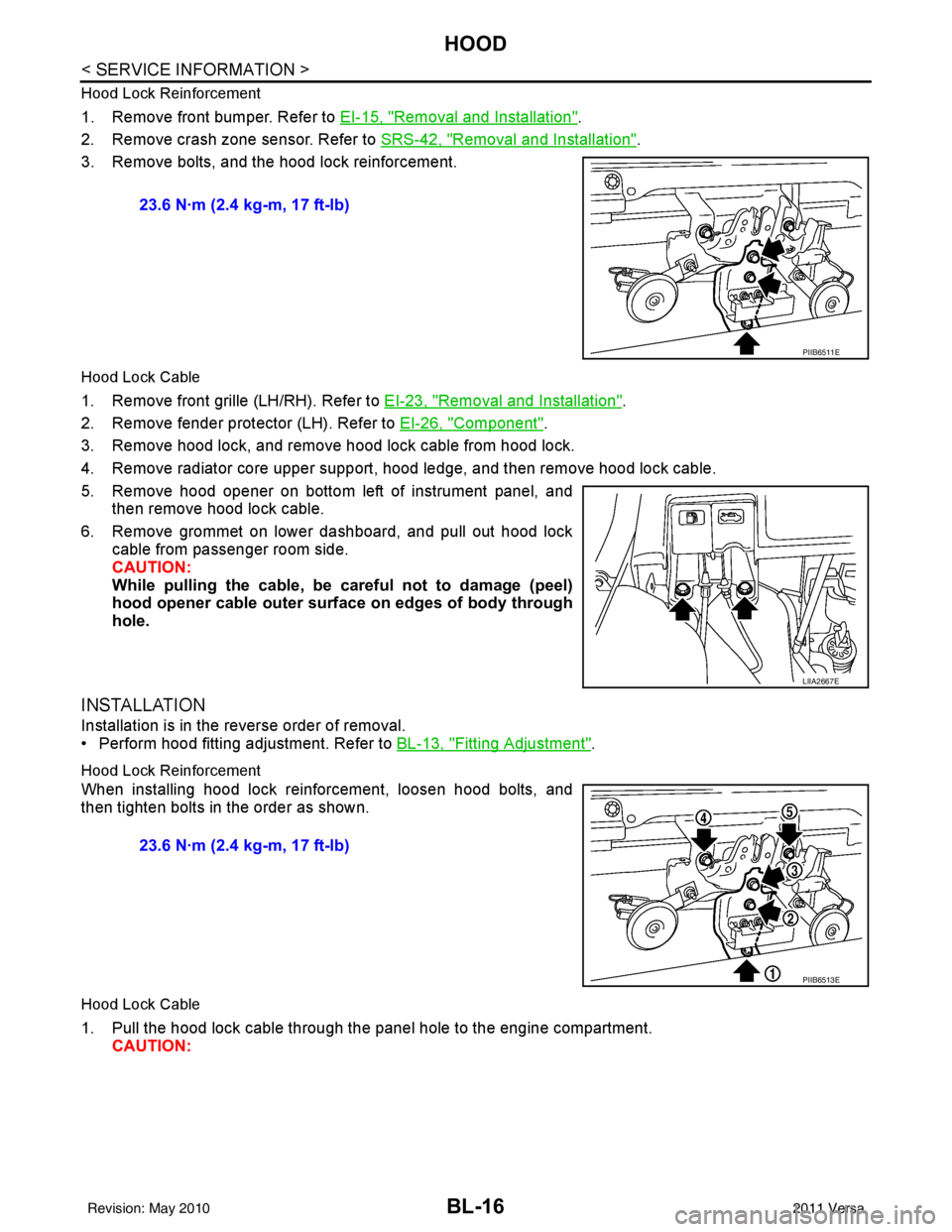
3. Remove bolts, and the hood lock reinforcement.
Hood Lock Cable
1. Remove front grille (LH/RH). Refer to EI-23, "Removal and Installation".
2. Remove fender protector (LH). Refer to EI-26, "
Component".
3. Remove hood lock, and remove hood lock cable from hood lock.
4. Remove radiator core upper support, hood ledge, and then remove hood lock cable.
5. Remove hood opener on bottom left of instrument panel, and then remove hood lock cable.
6. Remove grommet on lower dashboard, and pull out hood lock cable from passenger room side.
CAUTION:
While pulling the cable, be car eful not to damage (peel)
hood opener cable outer surface on edges of body through
hole.
INSTALLATION
Installation is in the reverse order of removal.
• Perform hood fitting adjustment. Refer to BL-13, "
Fitting Adjustment".
Hood Lock Reinforcement
When installing hood lock reinforcement, loosen hood bolts, and
then tighten bolts in the order as shown.
Hood Lock Cable
1. Pull the hood lock cable through the panel hole to the engine compartment. CAUTION: 23.6 N·m (2.4 kg-m, 17 ft-lb)
PIIB6511E
LIIA2667E
23.6 N·m (2.4 kg-m, 17 ft-lb)
PIIB6513E
Revision: May 2010
2011 Versa
Page 528 of 3787
BL-18
< SERVICE INFORMATION >
HOOD
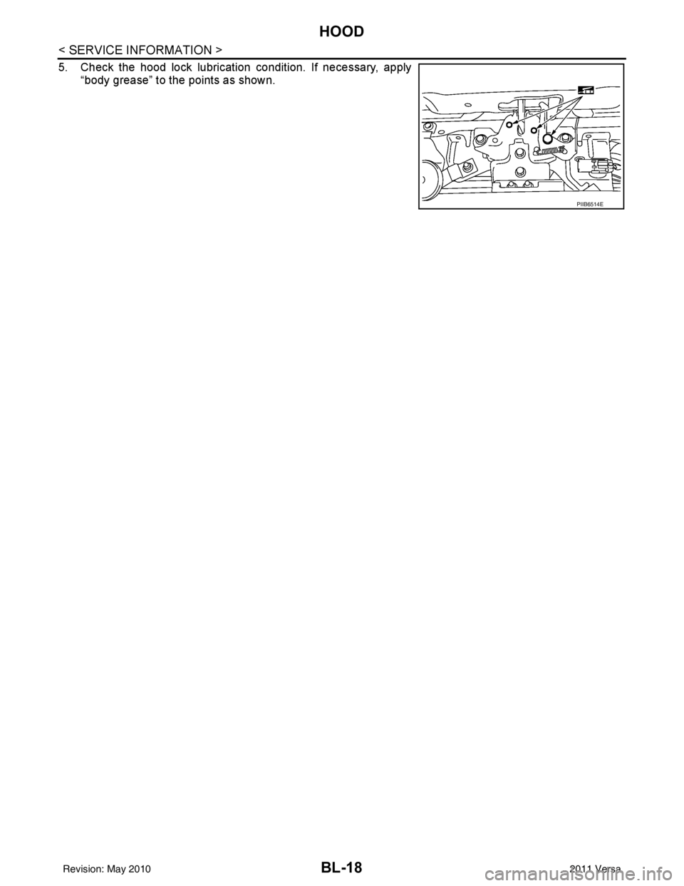
5. Check the hood lock lubrication condition. If necessary, apply“body grease” to the points as shown.
PIIB6514E
Revision: May 2010 2011 Versa
Page 533 of 3787

POWER DOOR LOCK SYSTEMBL-23
< SERVICE INFORMATION >
C
DE
F
G H
J
K L
M A
B
BL
N
O P
System DescriptionINFOID:0000000005929283
Power is supplied at all times
• through 40A fusible link (letter g, located in the fuse and fusible link box)
• to BCM terminal 70
• through 10A fuse [No. 8, located in the fuse block (J/B)]
• to BCM terminal 57
• through 10A fuse [No. 14, located in the fuse block (J/B)]
• to key switch terminal 2 (without Intelligent Key system)
• through 10A fuse [No. 31, located in the fuse block (J/B)]
• to key switch and ignition knob switch terminals 2 and 4 (with Intelligent Key system).
When key switch is ON (key is inserted in ignition key cylinder), power is supplied
• through key switch terminal 1 (without Intelligent Key system) or key switch and ignition knob terminal 1 (with Intelligent Key system)
• to BCM terminal 37.
Ground is supplied
• to BCM terminal 67
• through body grounds M57 and M61.
LOCK OPERATION
When the door is locked with main power window and door lock/unlock switch, ground is supplied
• to BCM terminal 45
• through main power window and door lock and unlock switch terminals 17 and 18
• through body grounds M57 and M61.
When the door is locked with power window and door lock/unlock switch RH, ground is supplied
• to BCM terminal 45
• through power window and door lock and unlock switch RH terminals 1 and 3
• through body grounds M57 and M61.
When the door is locked with front door lock assemb ly LH (key cylinder switch), ground is supplied
• to BCM terminal 8
• through front door lock assembly LH (key cylinder switch) terminals 4 and 6
• through body grounds M57 and M61.
UNLOCK OPERATION
When the door is unlocked with main power window and door lock/unlock switch, ground is supplied
• to BCM terminal 46
• through main power window and door lock/unlock switch terminals 6 and 17
• through body grounds M57 and M61.
When the door is unlocked with power window and door lock/unlock switch RH, ground is supplied
• to BCM terminal 46
• through power window and door lock and unlock switch RH terminals 2 and 3
• through body grounds M57 and M61.
When the door is unlocked with front door lock assemb ly LH (key cylinder switch), ground is supplied
• to BCM terminal 7
• through front door lock assembly LH (key cylinder switch) terminals 4 and 5
1. BCM M18, M19, M20
(view with glove box removed) 2. Intelligent Key unit M52
(if equipped) 3. Front door lock assembly LH (key cyl-
inder switch) D14
4. Front door switch LH B8, RH B108 5. Front door lock assembly LH (actuator) D14
Front door lock assembly RH (actuator)
D1146. Rear door switch LH B6, RH B116
7. Rear door lock actuator LH D205 RH D305 8. Key switch and ignition knob switch M73
(with A/T or CVT and Intelligent Key) 9. Key switch and ignition knob switch
M73 (with M/T and Intelligent Key)
10. Key switch and key lock solenoid M27 (without Intelligent key) 11. Main power window and door lock/un-
lock switch D7, D8
Power window and door lock/unlock
switch RH D105 12. Fuse block (with Intelligent Key)
(view with instrument panel LH re-
moved)
13. Passenger select unlock relay M2 (with Intelligent Key) 14. Back door lock assembly (back door
switch) D405 (hatchback view with back
door open) 15. Combination meter M24
Revision: May 2010
2011 Versa
Page 534 of 3787

BL-24
< SERVICE INFORMATION >
POWER DOOR LOCK SYSTEM
• through body grounds M57 and M61.
When the front door switch LH is ON (door is OPEN), ground is supplied
• to BCM terminal 47
• through front door switch LH terminal 2
• through front door switch LH case ground.
When the front door switch RH is ON (door is OPEN), ground is supplied
• to BCM terminal 12
• through front door switch RH terminal 2
• through front door switch RH case ground.
When the rear door switch LH is ON (door is OPEN), ground is supplied
• to BCM terminal 48
• through rear door switch LH terminal 1
• through rear door switch LH case ground.
When the rear door switch RH is ON (door is OPEN), ground is supplied
• to BCM terminal 13
• through rear door switch RH terminal 1
• through rear door switch RH case ground.
When the back door lock assembly (back door switch) ( hatchback) is ON (back door is OPEN), ground is sup-
plied
• to BCM terminal 43
• through back door lock assembly (back door switch) terminals 3 and 4
• through body grounds B117, B132 and D402.
OUTLINE
Functions available by operating the inside door lock and unlock switches
• Interlocked with the locking operation of door lock and unlock switch, door lock actuators of all doors are
locked.
• Interlocked with the unlocking operation of door lock and unlock switch, door lock actuators of all doors are
unlocked.
Functions available by operating the front door lock assembly LH (key cylinder switch)
• Interlocked with the locking operation of front door lock assembly LH (key cylinder switch), door lock actua-
tors of all doors are locked.
• When front door lock assembly LH (key cylinder switch) is unlocked, front door lock assembly LH (actuator)
is unlocked.
• When front door lock assembly LH (key cylinder swit ch) is unlocked for the second time within 5 seconds
after the first operation, front door lock assembly RH (actuator), rear door lock actuator LH and rear door
lock actuator RH are unlocked.
Key reminder door system
When door lock and unlock switch is operated to lock doors with ignition key inserted in key cylinder and any
door open, all door lock actuators are locked and then unlocked.
AUTOMATIC DOOR LOCKS (LOCK OPERATION)
The interlock door lock function is the function that locks all doors linked with the vehicle speed.
Vehicle Speed Sensing Auto Door Lock*1
All doors are locked when the vehicle speed reaches 24 km/h (15 MPH) or more.
BCM outputs the lock signal to all door lock actuators when it detects that the ignition switch is turned ON, all
doors are closed and the vehicle speed received from the combination meter via CAN communication
becomes 15 MPH (24 km/h) or more.
If a door is opened and closed at any time during one ignition cycle (OFF → ON), even after initial auto door
lock has taken place, the BCM will relock all doors when the vehicle speed reaches 15 MPH (24 km/h) or more
again.
Setting change of Automatic Door Locks (LOCK) Function
The lock operation setting of the autom atic door locks function can be changed.
With CONSULT-III
The ON/OFF switching of the automatic door locks (LOC K) function and the type selection of the automatic
door locks (LOCK) function can be performed at the WO RK SUPPORT setting of CONSULT-III. Refer to BL-
41, "CONSULT-III Function (BCM)".
Without CONSULT- III
The automatic door locks (LOCK) function can be swit ched ON/OFF by performing the following operation.
Revision: May 2010 2011 Versa
Page 562 of 3787
BL-52
< SERVICE INFORMATION >
POWER DOOR LOCK SYSTEM
5. Check continuity between BCM connector M19 terminal 46 andground.
OK or NG
OK >> Replace BCM. Refer to BCS-19, "Removal and Installa-
tion of BCM" .
NG >> Repair or replace harness.
Front Door Lock Assembly LH (Actuator) CheckINFOID:0000000005929298
1.CHECK FRONT DOOR LOCK ASSEMBLY LH (ACTUATOR) HARNESS
1. Turn ignition switch OFF.
2. Disconnect BCM and front door lock assembly LH (actuator).
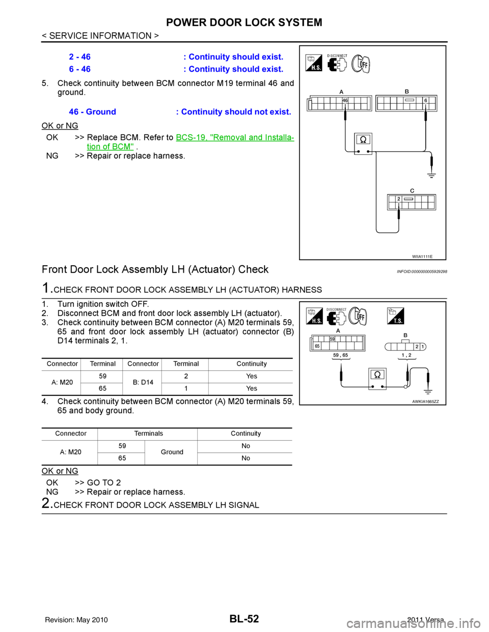
3. Check continuity between BCM connector (A) M20 terminals 59, 65 and front door lock assembly LH (actuator) connector (B)
D14 terminals 2, 1.
4. Check continuity between BCM connector (A) M20 terminals 59, 65 and body ground.
OK or NG
OK >> GO TO 2
NG >> Repair or replace harness.
2.CHECK FRONT DOOR LOCK ASSEMBLY LH SIGNAL 2 - 46
: Continuity should exist.
6 - 46 : Continuity should exist.
46 - Ground : Continuity should not exist.
WIIA1111E
Connector Terminal Connector Terminal Continuity
A: M20 59
B: D14 2Y
es
65 1Yes
Connector Terminals Continuity
A: M20 59
Ground No
65 No
AWKIA1665ZZ
Revision: May 2010 2011 Versa
Page 563 of 3787
POWER DOOR LOCK SYSTEMBL-53
< SERVICE INFORMATION >
C
DE
F
G H
J
K L
M A
B
BL
N
O P
1. Reconnect BCM.
2. Check voltage between BCM connector M20 terminals 59, 65 and ground.
OK or NG
OK >> Replace front door lock assembly LH (actuator). Refer to BL-167, "Removal and Installation" .
NG >> Replace BCM. Refer to BCS-19, "
Removal and Installation of BCM" .
Front Door Lock Assembly RH (Actuator) CheckINFOID:0000000006220781
1.CHECK FRONT DOOR LOCK ASSEMBLY RH (ACTUATOR) HARNESS
1. Turn ignition switch OFF.
2. Disconnect BCM and front door lock assembly RH (actuator).
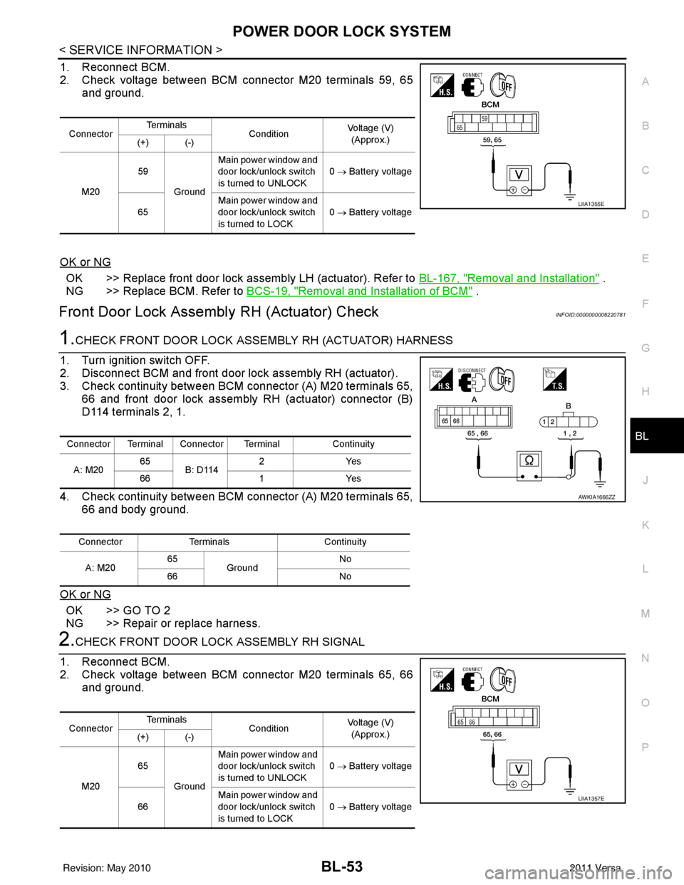
3. Check continuity between BCM connector (A) M20 terminals 65, 66 and front door lock assembly RH (actuator) connector (B)
D114 terminals 2, 1.
4. Check continuity between BCM connector (A) M20 terminals 65, 66 and body ground.
OK or NG
OK >> GO TO 2
NG >> Repair or replace harness.
2.CHECK FRONT DOOR LOCK ASSEMBLY RH SIGNAL
1. Reconnect BCM.
2. Check voltage between BCM connector M20 terminals 65, 66 and ground.
Connector Te r m i n a l s
ConditionVoltage (V)
(Approx.)
(+) (-)
M20 59
Ground Main power window and
door lock/unlock switch
is turned to UNLOCK
0
→ Battery voltage
65 Main power window and
door lock/unlock switch
is turned to LOCK 0
→ Battery voltage
LIIA1355E
Connector Terminal Connector Terminal Continuity
A: M20 65
B: D114 2Y
es
66 1Yes
Connector Terminals Continuity
A: M20 65
Ground No
66 No
AWKIA1666ZZ
ConnectorTe r m i n a l s
ConditionVoltage (V)
(Approx.)
(+) (-)
M20 65
Ground Main power window and
door lock/unlock switch
is turned to UNLOCK
0
→ Battery voltage
66 Main power window and
door lock/unlock switch
is turned to LOCK
0
→ Battery voltage
LIIA1357E
Revision: May 2010 2011 Versa
Page 564 of 3787

BL-54
< SERVICE INFORMATION >
POWER DOOR LOCK SYSTEM
OK or NG
OK >> Replace front door lock assembly RH (actuator). Refer to BL-167, "Removal and Installation" .
NG >> Replace BCM. Refer to BCS-19, "
Removal and Installation of BCM" .
Rear Door Lock Actuator LH/RH CheckINFOID:0000000005929299
1.CHECK DOOR LOCK ACTUATOR HARNESS
NOTE:
For models with Intelligent Key, insure that passenger select unlock relay remains connected during this test.
1. Turn ignition switch OFF.
2. Disconnect BCM and each door lock actuator.
3. Check continuity between BCM connector (A) M20 terminals 65, 66 and rear door lock actuator RH connector (B) D305, rear
door lock actuator LH connector (C) D205 terminals 2, 3.
4. Check continuity between BCM connector (A) M20 terminals 65, 66 and body ground.
OK or NG
OK >> GO TO 2
NG >> Check the following: • Without Intelligent Key: Repair or replace harness.
• With Intelligent Key: Repair or replace harness or pas-senger select unlock relay.
2.CHECK DOOR LOCK ACTUATOR SIGNAL
1. Reconnect BCM.
2. Check voltage between BCM connector M20 terminals 65, 66 and ground.
OK or NG
OK >> Replace rear door lock actuator LH/RH. Refer to BL-170, "Removal and Installation" .
NG >> Replace BCM. Refer to BCS-19, "
Removal and Installation of BCM" .
Front Door Lock Assembly LH (Key Cylinder Switch) CheckINFOID:0000000005929300
1.CHECK FRONT DOOR LOCK ASSEMB LY LH (KEY CYLINDER SWITCH)
With CONSULT-III
Connector Terminal Connector Terminal Continuity
A: M20 65
B: D305
C: D205 3Y
es
66 2Yes
Connector Terminals Continuity
A: M20 65
Ground No
66 No
LIIA2526E
ConnectorTe r m i n a l s
ConditionVoltage (V)
(Approx.)
(+) (-)
M20 65
Ground Main power window and
door lock/unlock switch is
turned to UNLOCK
0
→ Battery voltage
66 Main power window and
door lock/unlock switch is
turned to LOCK 0
→ Battery voltage
LIIA1357E
Revision: May 2010 2011 Versa
Page 565 of 3787
POWER DOOR LOCK SYSTEMBL-55
< SERVICE INFORMATION >
C
DE
F
G H
J
K L
M A
B
BL
N
O P
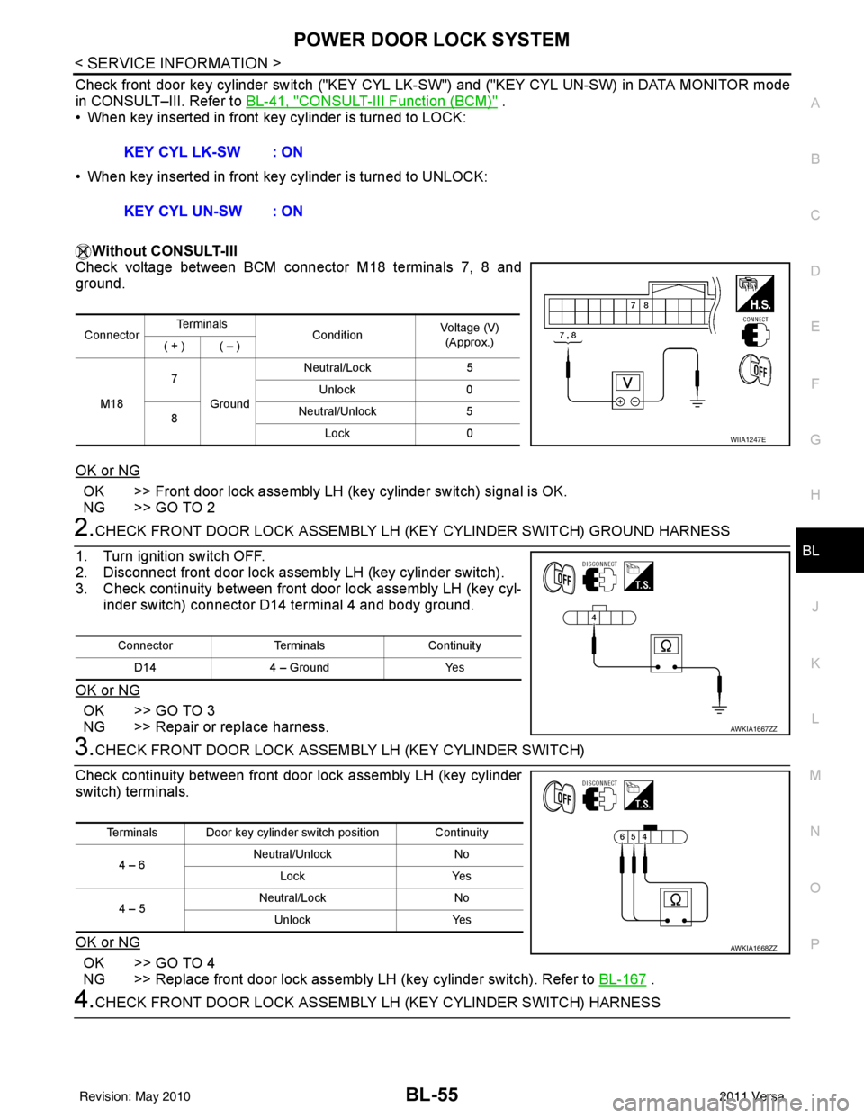
Check front door key cylinder switch ("KEY CYL LK -SW") and ("KEY CYL UN-SW) in DATA MONITOR mode
in CONSULT–III. Refer to BL-41, "
CONSULT-III Function (BCM)" .
• When key inserted in front key cylinder is turned to LOCK:
• When key inserted in front key cylinder is turned to UNLOCK:
Without CONSULT-III
Check voltage between BCM connector M18 terminals 7, 8 and
ground.
OK or NG
OK >> Front door lock assembly LH (key cylinder switch) signal is OK.
NG >> GO TO 2
2.CHECK FRONT DOOR LOCK ASSEMBLY LH (KEY CYLINDER SWITCH) GROUND HARNESS
1. Turn ignition switch OFF.
2. Disconnect front door lock assembly LH (key cylinder switch).
3. Check continuity between front door lock assembly LH (key cyl- inder switch) connector D14 terminal 4 and body ground.
OK or NG
OK >> GO TO 3
NG >> Repair or replace harness.
3.CHECK FRONT DOOR LOCK ASSEM BLY LH (KEY CYLINDER SWITCH)
Check continuity between front door lock assembly LH (key cylinder
switch) terminals.
OK or NG
OK >> GO TO 4
NG >> Replace front door lock assembly LH (key cylinder switch). Refer to BL-167
.
4.CHECK FRONT DOOR LOCK ASSEMBLY LH (KEY CYLINDER SWITCH) HARNESS
KEY CYL LK-SW : ON
KEY CYL UN-SW : ON
Connector
Te r m i n a l s
ConditionVoltage (V)
(Approx.)
( + ) ( – )
M18 7
Ground Neutral/Lock
5
Unlock 0
8 Neutral/Unlock
5
Lock 0
WIIA1247E
Connector TerminalsContinuity
D14 4 – Ground Yes
AWKIA1667ZZ
Terminals Door key cylinder switch position Continuity
4 – 6 Neutral/Unlock
No
Lock Yes
4 – 5 Neutral/Lock
No
Unlock Yes
AWKIA1668ZZ
Revision: May 2010 2011 Versa