2011 NISSAN TIIDA remove engine
[x] Cancel search: remove enginePage 143 of 3787
AT-126
< SERVICE INFORMATION >
P0740 TORQUE CONVERTER
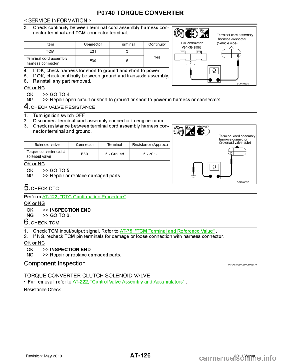
3. Check continuity between terminal cord assembly harness con-nector terminal and TCM connector terminal.
4. If OK, check harness for short to ground and short to power.
5. If OK, check continuity bet ween ground and transaxle assembly.
6. Reinstall any part removed.
OK or NG
OK >> GO TO 4.
NG >> Repair open circuit or short to ground or short to power in harness or connectors.
4.CHECK VALVE RESISTANCE
1. Turn ignition switch OFF.
2. Disconnect terminal cord assembly connector in engine room.
3. Check resistance between terminal cord assembly harness con- nector terminal and ground.
OK or NG
OK >> GO TO 5.
NG >> Repair or replace damaged parts.
5.CHECK DTC
Perform AT-123, "
DTC Confirmation Procedure" .
OK or NG
OK >> INSPECTION END
NG >> GO TO 6.
6.CHECK TCM
1. Check TCM input/output signal. Refer to AT-75, "
TCM Terminal and Reference Value" .
2. If NG, recheck TCM pin terminals for damage or loose connection with harness connector.
OK or NG
OK >> INSPECTION END
NG >> Repair or replace damaged parts.
Component InspectionINFOID:0000000005928171
TORQUE CONVERTER CLUTCH SOLENOID VALVE
• For removal, refer to AT-222, "Control Valve Assembly and Accumulators" .
Resistance Check
ItemConnector Terminal Continuity
TCM E313
Ye s
Terminal cord assembly
harness connector F30
5
SCIA3263E
Solenoid valve Connector Terminal Resistance (Approx.)
Torque converter clutch
solenoid valve F30 5 - Ground 5 - 20
Ω
SCIA3456E
Revision: May 2010 2011 Versa
Page 158 of 3787
P0750 SHIFT SOLENOID AAT-141
< SERVICE INFORMATION >
DE
F
G H
I
J
K L
M A
B
AT
N
O P
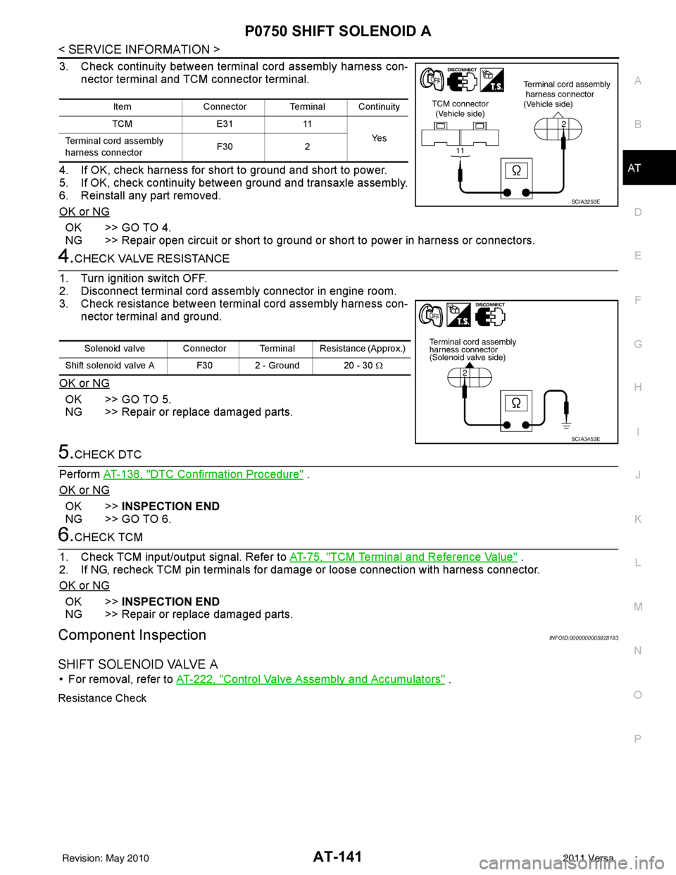
3. Check continuity between terminal cord assembly harness con- nector terminal and TCM connector terminal.
4. If OK, check harness for short to ground and short to power.
5. If OK, check continuity between ground and transaxle assembly.
6. Reinstall any part removed.
OK or NG
OK >> GO TO 4.
NG >> Repair open circuit or short to ground or short to power in harness or connectors.
4.CHECK VALVE RESISTANCE
1. Turn ignition switch OFF.
2. Disconnect terminal cord assembly connector in engine room.
3. Check resistance between terminal cord assembly harness con- nector terminal and ground.
OK or NG
OK >> GO TO 5.
NG >> Repair or replace damaged parts.
5.CHECK DTC
Perform AT-138, "
DTC Confirmation Procedure" .
OK or NG
OK >> INSPECTION END
NG >> GO TO 6.
6.CHECK TCM
1. Check TCM input/output signal. Refer to AT-75, "
TCM Terminal and Reference Value" .
2. If NG, recheck TCM pin terminals for dam age or loose connection with harness connector.
OK or NG
OK >> INSPECTION END
NG >> Repair or replace damaged parts.
Component InspectionINFOID:0000000005928193
SHIFT SOLENOID VALVE A
• For removal, refer to AT-222, "Control Valve Assembly and Accumulators" .
Resistance Check
Item Connector Terminal Continuity
TCM E3111
Ye s
Terminal cord assembly
harness connector F30
2
SCIA3250E
Solenoid valve Connector Terminal Resistance (Approx.)
Shift solenoid valve A F30 2 - Ground 20 - 30 Ω
SCIA3453E
Revision: May 2010 2011 Versa
Page 163 of 3787
AT-146
< SERVICE INFORMATION >
P0755 SHIFT SOLENOID B
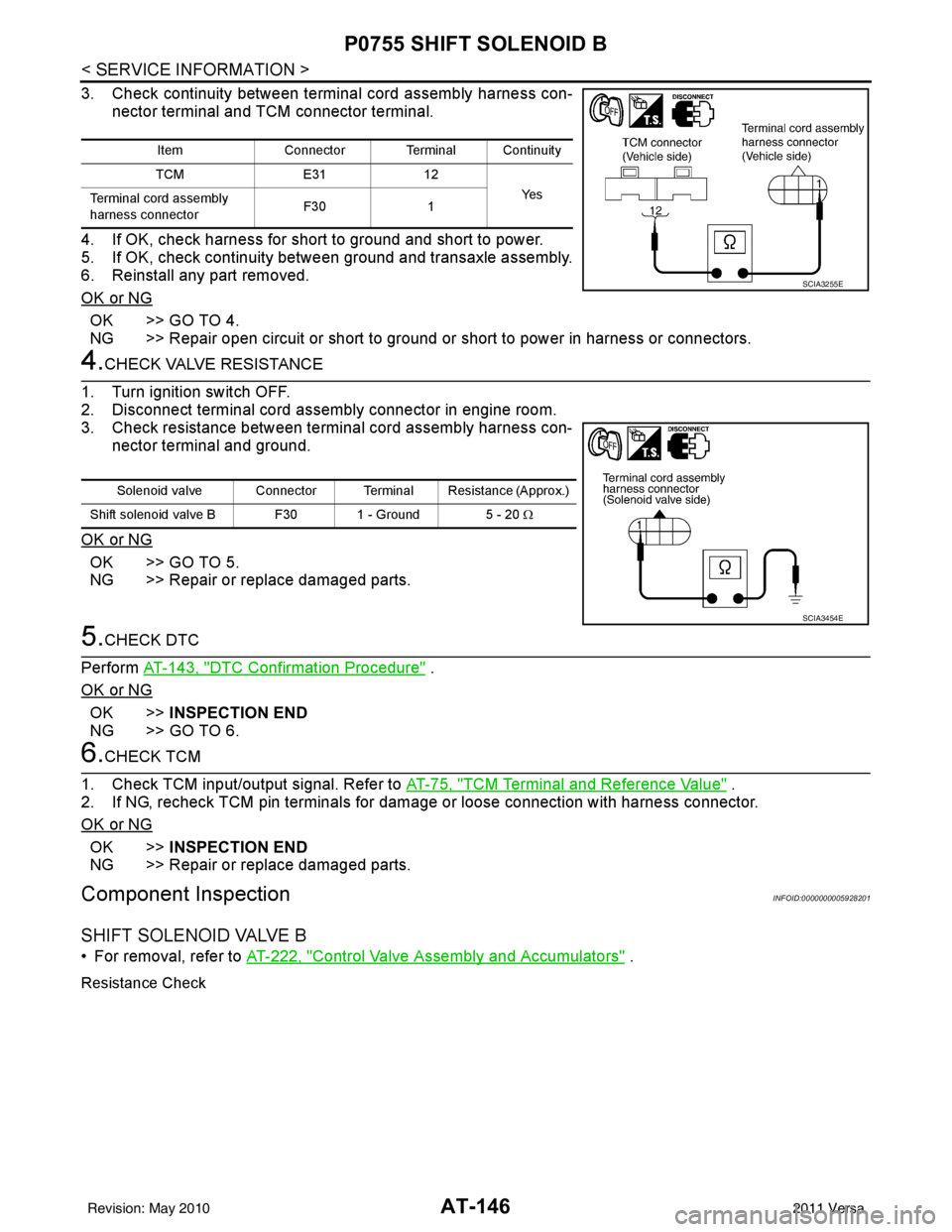
3. Check continuity between terminal cord assembly harness con-nector terminal and TCM connector terminal.
4. If OK, check harness for short to ground and short to power.
5. If OK, check continuity bet ween ground and transaxle assembly.
6. Reinstall any part removed.
OK or NG
OK >> GO TO 4.
NG >> Repair open circuit or short to ground or short to power in harness or connectors.
4.CHECK VALVE RESISTANCE
1. Turn ignition switch OFF.
2. Disconnect terminal cord assembly connector in engine room.
3. Check resistance between terminal cord assembly harness con- nector terminal and ground.
OK or NG
OK >> GO TO 5.
NG >> Repair or replace damaged parts.
5.CHECK DTC
Perform AT-143, "
DTC Confirmation Procedure" .
OK or NG
OK >> INSPECTION END
NG >> GO TO 6.
6.CHECK TCM
1. Check TCM input/output signal. Refer to AT-75, "
TCM Terminal and Reference Value" .
2. If NG, recheck TCM pin terminals for damage or loose connection with harness connector.
OK or NG
OK >> INSPECTION END
NG >> Repair or replace damaged parts.
Component InspectionINFOID:0000000005928201
SHIFT SOLENOID VALVE B
• For removal, refer to AT-222, "Control Valve Assembly and Accumulators" .
Resistance Check
ItemConnector Terminal Continuity
TCM E3112
Ye s
Terminal cord assembly
harness connector F30
1
SCIA3255E
Solenoid valve Connector Terminal Resistance (Approx.)
Shift solenoid valve B F30 1 - Ground 5 - 20 Ω
SCIA3454E
Revision: May 2010 2011 Versa
Page 168 of 3787
P1760 OVERRUN CLUTCH SOLENOIDAT-151
< SERVICE INFORMATION >
DE
F
G H
I
J
K L
M A
B
AT
N
O P
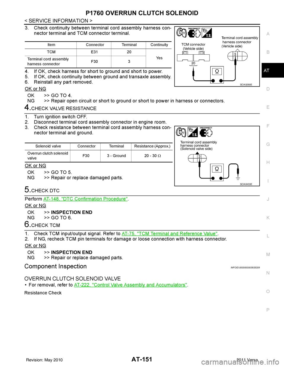
3. Check continuity between terminal cord assembly harness con- nector terminal and TCM connector terminal.
4. If OK, check harness for short to ground and short to power.
5. If OK, check continuity between ground and transaxle assembly.
6. Reinstall any part removed.
OK or NG
OK >> GO TO 4.
NG >> Repair open circuit or short to ground or short to power in harness or connectors.
4.CHECK VALVE RESISTANCE
1. Turn ignition switch OFF.
2. Disconnect terminal cord assembly connector in engine room.
3. Check resistance between terminal cord assembly harness con- nector terminal and ground.
OK or NG
OK >> GO TO 5.
NG >> Repair or replace damaged parts.
5.CHECK DTC
Perform AT-148, "
DTC Confirmation Procedure".
OK or NG
OK >> INSPECTION END
NG >> GO TO 6.
6.CHECK TCM
1. Check TCM input/output signal. Refer to AT-75, "
TCM Terminal and Reference Value".
2. If NG, recheck TCM pin terminals for dam age or loose connection with harness connector.
OK or NG
OK >> INSPECTION END
NG >> Repair or replace damaged parts.
Component InspectionINFOID:0000000005928209
OVERRUN CLUTCH SOLENOID VALVE
• For removal, refer to AT-222, "Control Valve Assembly and Accumulators".
Resistance Check
Item Connector Terminal Continuity
TCM E3120
Ye s
Terminal cord assembly
harness connector F30
3
SCIA3260E
Solenoid valve Connector Terminal Resistance (Approx.)
Overrun clutch solenoid
valve F30 3 - Ground 20 - 30
Ω
SCIA3455E
Revision: May 2010 2011 Versa
Page 177 of 3787
AT-160
< SERVICE INFORMATION >
BATT/FLUID TEMP SEN
OK >> GO TO 7.
NG >> Repair open circuit or short to ground or short to power in harness or connectors.
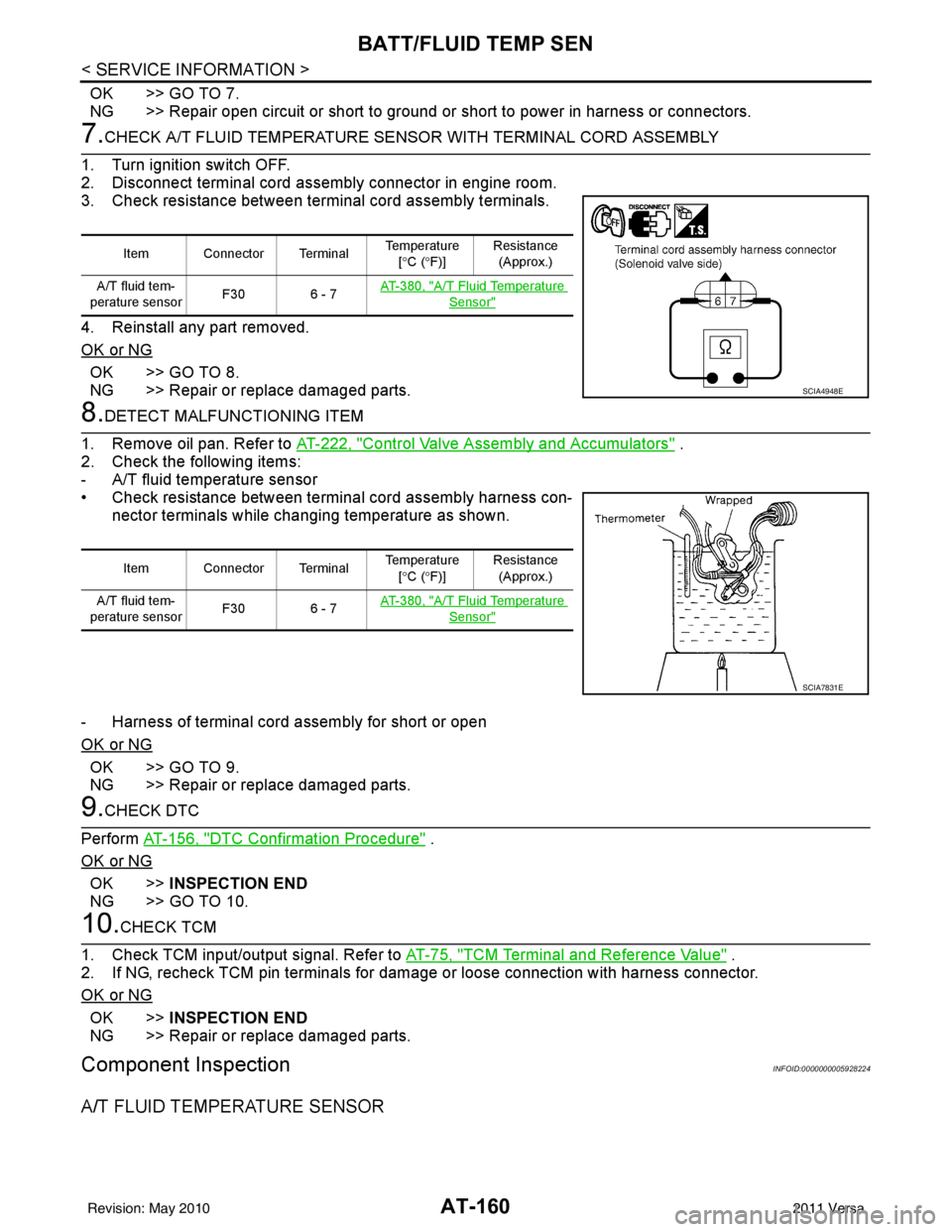
7.CHECK A/T FLUID TEMPERATURE SENSOR WITH TERMINAL CORD ASSEMBLY
1. Turn ignition switch OFF.
2. Disconnect terminal cord assembly connector in engine room.
3. Check resistance between terminal cord assembly terminals.
4. Reinstall any part removed.
OK or NG
OK >> GO TO 8.
NG >> Repair or replace damaged parts.
8.DETECT MALFUNCTIONING ITEM
1. Remove oil pan. Refer to AT-222, "
Control Valve Assembly and Accumulators" .
2. Check the following items:
- A/T fluid temperature sensor
• Check resistance between terminal cord assembly harness con- nector terminals while changing temperature as shown.
- Harness of terminal cord assembly for short or open
OK or NG
OK >> GO TO 9.
NG >> Repair or replace damaged parts.
9.CHECK DTC
Perform AT-156, "
DTC Confirmation Procedure" .
OK or NG
OK >> INSPECTION END
NG >> GO TO 10.
10.CHECK TCM
1. Check TCM input/output signal. Refer to AT-75, "
TCM Terminal and Reference Value" .
2. If NG, recheck TCM pin terminals for damage or loose connection with harness connector.
OK or NG
OK >> INSPECTION END
NG >> Repair or replace damaged parts.
Component InspectionINFOID:0000000005928224
A/T FLUID TEMPERATURE SENSOR
Item Connector Terminal Temperature
[° C ( °F)] Resistance
(Approx.)
A/T fluid tem-
perature sensor F30 6 - 7 AT- 3 8 0 , "
A/T Fluid Temperature
Sensor"
SCIA4948E
Item Connector Terminal Temperature
[° C ( °F)] Resistance
(Approx.)
A/T fluid tem-
perature sensor F30 6 - 7 AT- 3 8 0 , "
A/T Fluid Temperature
Sensor"
SCIA7831E
Revision: May 2010
2011 Versa
Page 213 of 3787

AT-196
< SERVICE INFORMATION >
TROUBLE DIAGNOSIS FOR SYMPTOMS
OK >>INSPECTION END
NG >> GO TO 3.
3.CHECK TCM
1. Check TCM input/output signals. Refer to AT-75, "
TCM Terminal and Reference Value" .
2. If NG, recheck TCM pin terminals for damage or loose connection with harness connector.
OK or NG
OK >> INSPECTION END
NG >> Repair or replace damaged parts.
Engine Speed Does Not Return to Idle (Light Braking D4→ D3)INFOID:0000000005928261
SYMPTOM:
Engine speed does not smoothly return to idle when A/T shifts from D4 to D3 on “Cruise Test — Part
1”.
DIAGNOSTIC PROCEDURE
1.CHECK SELF-DIAGNOSTIC RESULTS
Perform self-diagnosis. Refer to AT-77, "
CONSULT-III Function (TRANSMISSION)" or AT-82, "Diagnosis Pro-
cedure without CONSULT-III" .
Is any malfunction detected by self-diagnostic results?
YES >> Check the malfunctioning system. Refer to AT-77, "CONSULT-III Function (TRANSMISSION)" or
AT-82, "
Diagnosis Procedure without CONSULT-III" .
NO >> GO TO 2.
2.CHECK ACCELERATOR PEDAL POSITION SENSOR
Check accelerator pedal position sensor. Refer to EC-415, "
Description" (HR16DE), EC-982, "Component
Description" (MR18DE).
OK or NG
OK >> GO TO 3.
NG >> Repair or replace accelerator pedal position sensor.
3.CHECK A/T FLUID CONDITION
1. Remove oil pan. Refer to AT-237, "
Component" .
2. Check A/T fluid condition. Refer to AT-51, "
Inspections Before Trouble Diagnosis" .
OK or NG
OK >> GO TO 5.
NG >> GO TO 4.
4.DETECT MALFUNCTIONING ITEM
1. Remove control valve assembly. Refer to AT-222, "
Control Valve Assembly and Accumulators" .
2. Check the following items:
- Overrun clutch control valve
- Overrun clutch reducing valve
- Overrun clutch solenoid valve
3. Disassemble A/T. Refer to AT-257, "
Disassembly" .
4. Check the following items:
- Overrun clutch assembly. Refer to AT-307, "
Forward and Overrun Clutches" .
OK or NG
OK >> GO TO 6.
NG >> Repair or replace damaged parts.
5.DETECT MALFUNCTIONING ITEM
1. Remove control valve assembly. Refer to AT-222, "
Control Valve Assembly and Accumulators" .
2. Check the following items:
- Overrun clutch control valve
- Overrun clutch reducing valve
- Overrun clutch solenoid valve
Revision: May 2010 2011 Versa
Page 217 of 3787
AT-200
< SERVICE INFORMATION >
TROUBLE DIAGNOSIS FOR SYMPTOMS
OK >> GO TO 3
NG >> Check transmission range switch. Refer to AT-175, "
Component Inspection" .
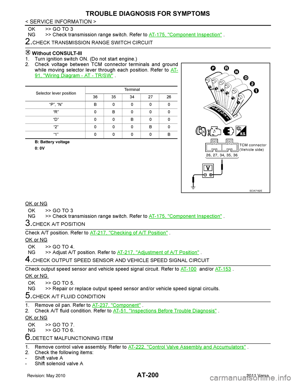
2.CHECK TRANSMISSION RANGE SWITCH CIRCUIT
Without CONSULT-III
1. Turn ignition switch ON. (Do not start engine.)
2. Check voltage between TCM connector terminals and ground
while moving selector lever through each position. Refer to AT-
91, "Wiring Diagram - AT - TR/SW" .
B: Battery voltage
0: 0V
OK or NG
OK >> GO TO 3
NG >> Check transmission range switch. Refer to AT-175, "
Component Inspection" .
3.CHECK A/T POSITION
Check A/T position. Refer to AT-217, "
Checking of A/T Position" .
OK or NG
OK >> GO TO 4.
NG >> Adjust A/T position. Refer to AT-217, "
Adjustment of A/T Position" .
4.CHECK OUTPUT SPEED SENSOR AND VEHICLE SPEED SIGNAL CIRCUIT
Check output speed sensor and vehicle speed signal circuit. Refer to AT-100
and/or AT-153 .
OK or NG
OK >> GO TO 5.
NG >> Repair or replace output speed sens or and/or vehicle speed signal circuits.
5.CHECK A/T FLUID CONDITION
1. Remove oil pan. Refer to AT-237, "
Component" .
2. Check A/T fluid condition. Refer to AT-51, "
Inspections Before Trouble Diagnosis" .
OK or NG
OK >> GO TO 7.
NG >> GO TO 6.
6.DETECT MALFUNCTIONING ITEM
1. Remove control valve assembly. Refer to AT-222, "
Control Valve Assembly and Accumulators" .
2. Check the following items:
- Shift valve A
- Shift solenoid valve A
Selector lever position Te r m i n a l
36 35 34 27 26
“P”, “N” B0000 “R” 0B000
“D” 0 0 B 0 0
“2” 000B0
“1” 0000B
SCIA7162E
Revision: May 2010 2011 Versa
Page 226 of 3787
A/T SHIFT LOCK SYSTEMAT-209
< SERVICE INFORMATION >
DE
F
G H
I
J
K L
M A
B
AT
N
O P
• Selector lever can be moved fr om “P” position with ignition key in ON position and brake pedal
released.
• Selector lever can be moved from “P” position when ignition switch is removed from key cylinder.
SYMPTOM 2:
• Ignition key cannot be removed when sel ector lever is set to “P” position.
• Ignition key can be removed wh en selector lever is set to any position except “P” position.
1.CHECK KEY INTERLOCK CABLE
Check key interlock cable for damage.
OK or NG
OK >> GO TO 2.
NG >> Repair key interlock cable. Refer to AT-219, "
Removal and Installation" .
2.CHECK A/T POSITION
Check A/T position. Refer to AT-217, "
Checking of A/T Position" .
OK or NG
OK >> GO TO 3.
NG >> Adjust control cable. Refer to AT-217, "
Adjustment of A/T Position" .
3.CHECK SHIFT LOCK SOLENOID AND PARK POSITION SWITCH
1. Turn ignition switch ON. (Do not start engine.)
2. Selector lever is set in “P” position.
3. Check operation sound.
OK or NG
OK >> INSPECTION END
NG - 1 >> With intelligent key: GO TO 4.
NG - 2 >> Without intelligent key: GO TO 5.
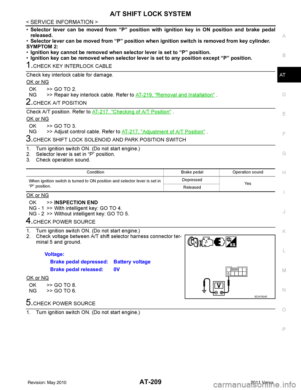
4.CHECK POWER SOURCE
1. Turn ignition switch ON. (Do not start engine.)
2. Check voltage between A/T shift selector harness connector ter- minal 5 and ground.
OK or NG
OK >> GO TO 8.
NG >> GO TO 6.
5.CHECK POWER SOURCE
1. Turn ignition switch ON. (Do not start engine.)
Condition Brake pedalOperation sound
When ignition switch is turned to ON position and selector lever is set in
“P” position. Depressed
Ye s
Released
Voltage:
Brake pedal depressed: Battery voltage
Brake pedal released: 0V
SCIA7934E
Revision: May 2010 2011 Versa