Page 234 of 3787

SHIFT CONTROL SYSTEMAT-217
< SERVICE INFORMATION >
DE
F
G H
I
J
K L
M A
B
AT
N
O P
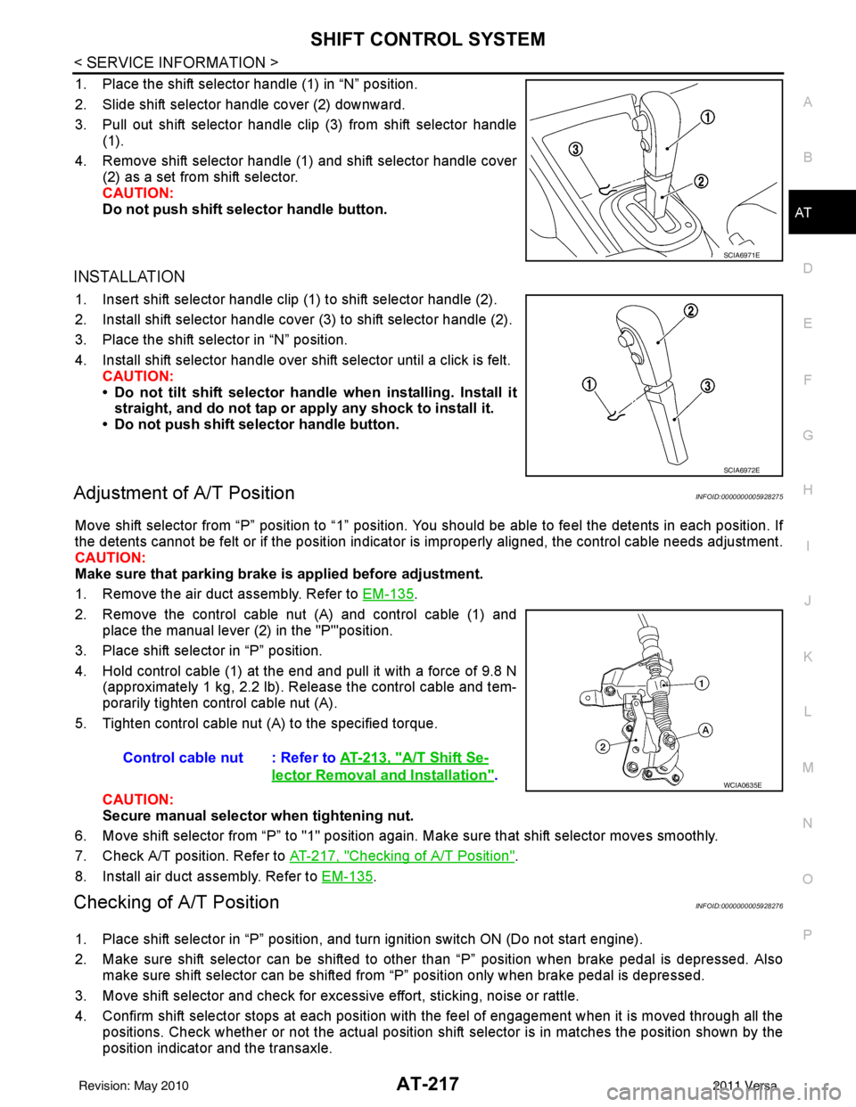
1. Place the shift selector handle (1) in “N” position.
2. Slide shift selector handle cover (2) downward.
3. Pull out shift selector handle clip (3) from shift selector handle (1).
4. Remove shift selector handle (1) and shift selector handle cover (2) as a set from shift selector.
CAUTION:
Do not push shift selector handle button.
INSTALLATION
1. Insert shift selector handle clip (1) to shift selector handle (2).
2. Install shift selector handle cover (3) to shift selector handle (2).
3. Place the shift selector in “N” position.
4. Install shift selector handle over shift selector until a click is felt.
CAUTION:
• Do not tilt shift selector hand le when installing. Install it
straight, and do not tap or ap ply any shock to install it.
• Do not push shift selector handle button.
Adjustment of A/T PositionINFOID:0000000005928275
Move shift selector from “P” position to “1” position. You should be able to feel the detents in each position. If
the detents cannot be felt or if the position indicator is improperly aligned, the control cable needs adjustment.
CAUTION:
Make sure that parking brake is applied before adjustment.
1. Remove the air duct assembly. Refer to EM-135
.
2. Remove the control cable nut (A) and control cable (1) and place the manual lever (2) in the "P'"position.
3. Place shift selector in “P” position.
4. Hold control cable (1) at the end and pull it with a force of 9.8 N (approximately 1 kg, 2.2 lb). Release the control cable and tem-
porarily tighten control cable nut (A).
5. Tighten control cable nut (A) to the specified torque.
CAUTION:
Secure manual selector when tightening nut.
6. Move shift selector from “P” to "1" position again. Make sure that shift selector moves smoothly.
7. Check A/T position. Refer to AT-217, "
Checking of A/T Position".
8. Install air duct assembly. Refer to EM-135
.
Checking of A/T PositionINFOID:0000000005928276
1. Place shift selector in “P” position, and tu rn ignition switch ON (Do not start engine).
2. Make sure shift selector can be shifted to other than “P” position when brake pedal is depressed. Also make sure shift selector can be shifted from “P” position only when brake pedal is depressed.
3. Move shift selector and check for excessive effort, sticking, noise or rattle.
4. Confirm shift selector stops at each position with the feel of engagement when it is moved through all the
positions. Check whether or not the ac tual position shift selector is in matches the position shown by the
position indicator and the transaxle.
SCIA6971E
SCIA6972E
Control cable nut : Refer to AT-213, "A/T Shift Se-
lector Removal and Installation".WCIA0635E
Revision: May 2010 2011 Versa
Page 239 of 3787

AT-222
< SERVICE INFORMATION >
ON-VEHICLE SERVICE
ON-VEHICLE SERVICE
Control Valve Assembly and AccumulatorsINFOID:0000000005928278
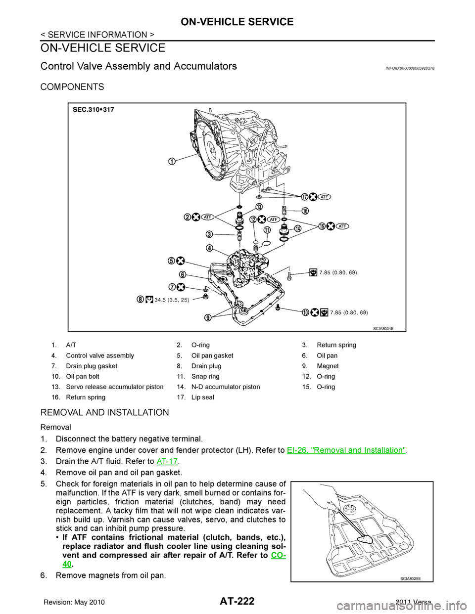
COMPONENTS
REMOVAL AND INSTALLATION
Removal
1. Disconnect the battery negative terminal.
2. Remove engine under cover and fender protector (LH). Refer to EI-26, "
Removal and Installation".
3. Drain the A/T fluid. Refer to AT- 1 7
.
4. Remove oil pan and oil pan gasket.
5. Check for foreign materials in oil pan to help determine cause of malfunction. If the ATF is very dark, smell burned or contains for-
eign particles, friction material (clutches, band) may need
replacement. A tacky film that will not wipe clean indicates var-
nish build up. Varnish can cause valves, servo, and clutches to
stick and can inhibit pump pressure.
•If ATF contains frictional ma terial (clutch, bands, etc.),
replace radiator and flush cool er line using cleaning sol-
vent and compressed air after repair of A/T. Refer to CO-
40.
6. Remove magnets from oil pan.
1. A/T 2. O-ring 3. Return spring
4. Control valve assembly 5. Oil pan gasket6. Oil pan
7. Drain plug gasket 8. Drain plug9. Magnet
10. Oil pan bolt 11. Snap ring 12. O-ring
13. Servo release accumulator piston 14. N-D accumulator piston 15. O-ring
16. Return spring 17. Lip seal
SCIA8024E
SCIA8025E
Revision: May 2010 2011 Versa
Page 250 of 3787
TRANSAXLE ASSEMBLYAT-233
< SERVICE INFORMATION >
DE
F
G H
I
J
K L
M A
B
AT
N
O P
TRANSAXLE ASSEMBLY
Removal and InstallationINFOID:0000000005928284
COMPONENTS
REMOVAL
1. Remove the engine and transaxle as an assembly. Refer to EM-197, "Removal and Installation".
1. A/T fluid level gauge2. A/T fluid charging pipe 3. O-ring
4. Fluid cooler tube 5. Copper washer 6. Bracket
7. Fluid cooler tube 8. A/T assembly9. Engine mounting bracket (LH)
10. Bracket 11. Gusset A. Refer to "INSTALLATION".
AWDIA0659ZZ
Revision: May 2010 2011 Versa
Page 251 of 3787

AT-234
< SERVICE INFORMATION >
TRANSAXLE ASSEMBLY
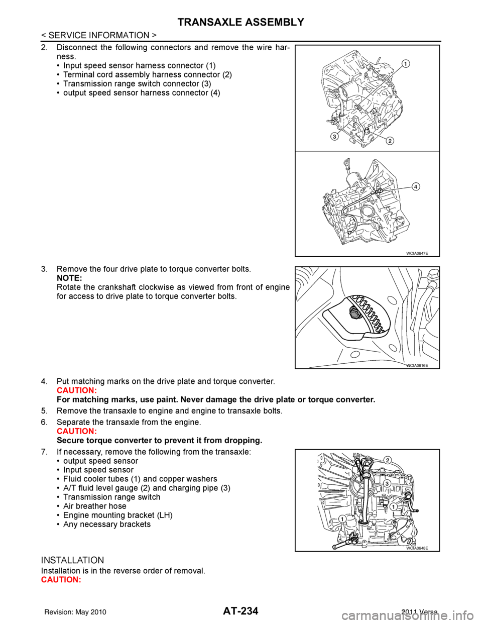
2. Disconnect the following connectors and remove the wire har-ness.
• Input speed sensor harness connector (1)
• Terminal cord assembly harness connector (2)
• Transmission range switch connector (3)
• output speed sensor harness connector (4)
3. Remove the four drive plate to torque converter bolts. NOTE:
Rotate the crankshaft clockwise as viewed from front of engine
for access to drive plate to torque converter bolts.
4. Put matching marks on the drive plate and torque converter. CAUTION:
For matching marks, use paint. Never dama ge the drive plate or torque converter.
5. Remove the transaxle to engine and engine to transaxle bolts.
6. Separate the transaxle from the engine. CAUTION:
Secure torque converter to prevent it from dropping.
7. If necessary, remove the following from the transaxle: • output speed sensor
• Input speed sensor
• Fluid cooler tubes (1) and copper washers
• A/T fluid level gauge (2) and charging pipe (3)
• Transmission range switch
• Air breather hose
• Engine mounting bracket (LH)
• Any necessary brackets
INSTALLATION
Installation is in the reverse order of removal.
CAUTION:
WCIA0647E
WCIA0616E
WCIA0648E
Revision: May 2010 2011 Versa
Page 279 of 3787
AT-262
< SERVICE INFORMATION >
DISASSEMBLY
• HR16DE engine models
• MR18DE engine models
b. Remove bracket from converter housing
c. Remove converter housing by tapping it lightly.
d. Remove O-ring from differential lubricant hole.
24. Remove final drive assembly from transaxle case.
SCIA6211J
SCIA7970E
SCIA3281E
SAT228F
Revision: May 2010 2011 Versa
Page 280 of 3787
DISASSEMBLYAT-263
< SERVICE INFORMATION >
DE
F
G H
I
J
K L
M A
B
AT
N
O P
25. Remove differential side bearing outer race from transaxle case and converter housing. (MR18DE engine models)
26. Remove differential side bearing adjusting shim from transaxle case.
27. Remove RH differential side oil seal from converter housing using a suitable tool.
CAUTION:
Be careful not to scratch converter housing.
28. Remove differential lubricant tube (1) and clips (2) from con- verter housing.
: Bolt
29. Remove oil pump assembly according to the following procedures. Tool number : KV381054S0 (J-34286)
SCIA5378E
SCIA4938E
SCIA3283E
SCIA7817E
Revision: May 2010
2011 Versa
Page 287 of 3787
AT-270
< SERVICE INFORMATION >
DISASSEMBLY
41. Remove overrun clutch hub (1) from forward clutch drum.
42. Remove thrust washer (1) from overrun clutch hub (2).•Inspect thrust washer (1) and overrun clutch hub (2), and
replace if damaged or worn.
43. Remove forward clutch assembly and overrun clutch assembly (1) from transaxle case.
44. Remove needle bearing (1) and thrust washer (2) from bearing retainer.
•Inspect needle bearing (1) and thrust washer (2), and
replace damaged or worn.
45. Remove output shaft assembly according to the following procedures.
a. HR16DE engine models.
SCIA5898J
SCIA5899J
SCIA5900J
SCIA5901J
Revision: May 2010 2011 Versa
Page 288 of 3787
DISASSEMBLYAT-271
< SERVICE INFORMATION >
DE
F
G H
I
J
K L
M A
B
AT
N
O P
i. Remove side cover bolts (1), then remove side cover by lightly tapping it with a soft hammer.
CAUTION:
Be careful not to damage cover.
ii. Remove side cover gasket from side cover.
iii. Set manual shaft in "P" position to lock idler gear and output gear.
iv. Unlock both idler gear and output gear lock nuts with a suitable tool.
v. Remove idler gear and output gear lock nuts.
vi. Remove out put gear (1) and idler gear (2) using Tool (A).
vii. Removing reduction pinion gear and output shaft from transaxle case.
viii. Remove reduction pinion gear adjusting shim (1) from reduction pinion gear (2).
ix. Remove output gear adjusting spacer (3) from output shaft (4).
b. MR18DE engine models.
SCIA6039J
SAT704D
Tool number : ST27180001 (J-25726-A)
SCIA6991E
SCIA5902J
Revision: May 2010 2011 Versa