Page 340 of 3787
REPAIR FOR COMPONENT PARTSAT-323
< SERVICE INFORMATION >
DE
F
G H
I
J
K L
M A
B
AT
N
O P
MR18DE engine models
DISASSEMBLY
1. Remove seal rings (1) from output shaft (2) and bearing retainer (3).
• HR16DE engine models
SCIA7944E
1. Lock nut 2. Idler gear3. Idler gear bearing
4. Reduction pinion gear adjusting shim 5. Reduction pinion gear bearing 6. Reduction pinion gear
7. Seal ring 8. Snap ring9. Radial needle bearing
10. Bearing retainer 11. Thrust needle bearing 12. Seal ring
13. Output shaft 14. Output shaft bearing15. Output shaft adjusting shim
JPDIA0288ZZ
Revision: May 2010 2011 Versa
Page 341 of 3787

AT-324
< SERVICE INFORMATION >
REPAIR FOR COMPONENT PARTS
• MR18DE engine models
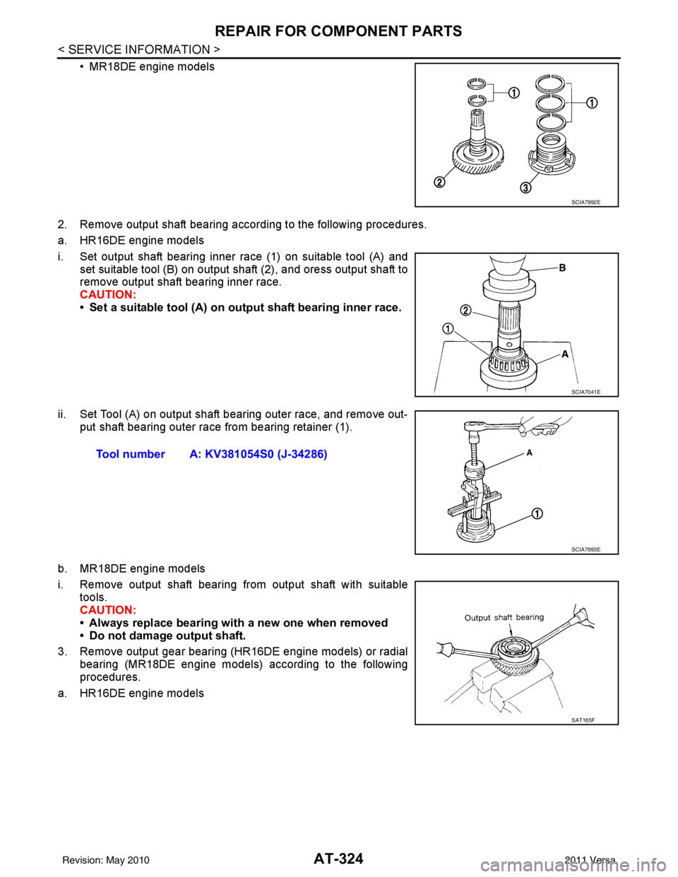
2. Remove output shaft bearing according to the following procedures.
a. HR16DE engine models
i. Set output shaft bearing inner race (1) on suitable tool (A) and set suitable tool (B) on output shaft (2), and oress output shaft to
remove output shaft bearing inner race.
CAUTION:
• Set a suitable tool (A) on output shaft bearing inner race.
ii. Set Tool (A) on output shaft bearing outer race, and remove out- put shaft bearing outer race from bearing retainer (1).
b. MR18DE engine models
i. Remove output shaft bearing from output shaft with suitable tools.
CAUTION:
• Always replace bearing with a new one when removed
• Do not damage output shaft.
3. Remove output gear bearing (HR16DE engine models) or radial bearing (MR18DE engine models) according to the following
procedures.
a. HR16DE engine models
SCIA7992E
SCIA7041E
Tool number A: KV381054S0 (J-34286)
SCIA7993E
SAT165F
Revision: May 2010 2011 Versa
Page 342 of 3787
REPAIR FOR COMPONENT PARTSAT-325
< SERVICE INFORMATION >
DE
F
G H
I
J
K L
M A
B
AT
N
O P
i. Insert suitable tool (A) between the mating surfaces of output gear (1) and output gear bearing inner race (2), and enlarge the
gap.
CAUTION:
Be careful not to damage output gear (1).
ii. Set suitable tool (B) on output gear (1), and remove output gear bearing inner race (2) with a suitable tool (C) as shown.
iii. Set Tool (A) on output gear bearing outer race (1), and remove output gear bearing outer race from bearing retainer (2).
b. MR18DE engine models
i. Remove snap ring (1) using suit able tool from bearing retainer
(2).
ii. Remove radial needle bearing from bearing retainer (1) using Tool (A).
SCIA7042E
SCIA7043E
JSDIA0241ZZ
Tool number A: KV381054S0 (J-34286)
SCIA7993E
Revision: May 2010 2011 Versa
Page 349 of 3787

AT-332
< SERVICE INFORMATION >
REPAIR FOR COMPONENT PARTS
MR18DE engine models
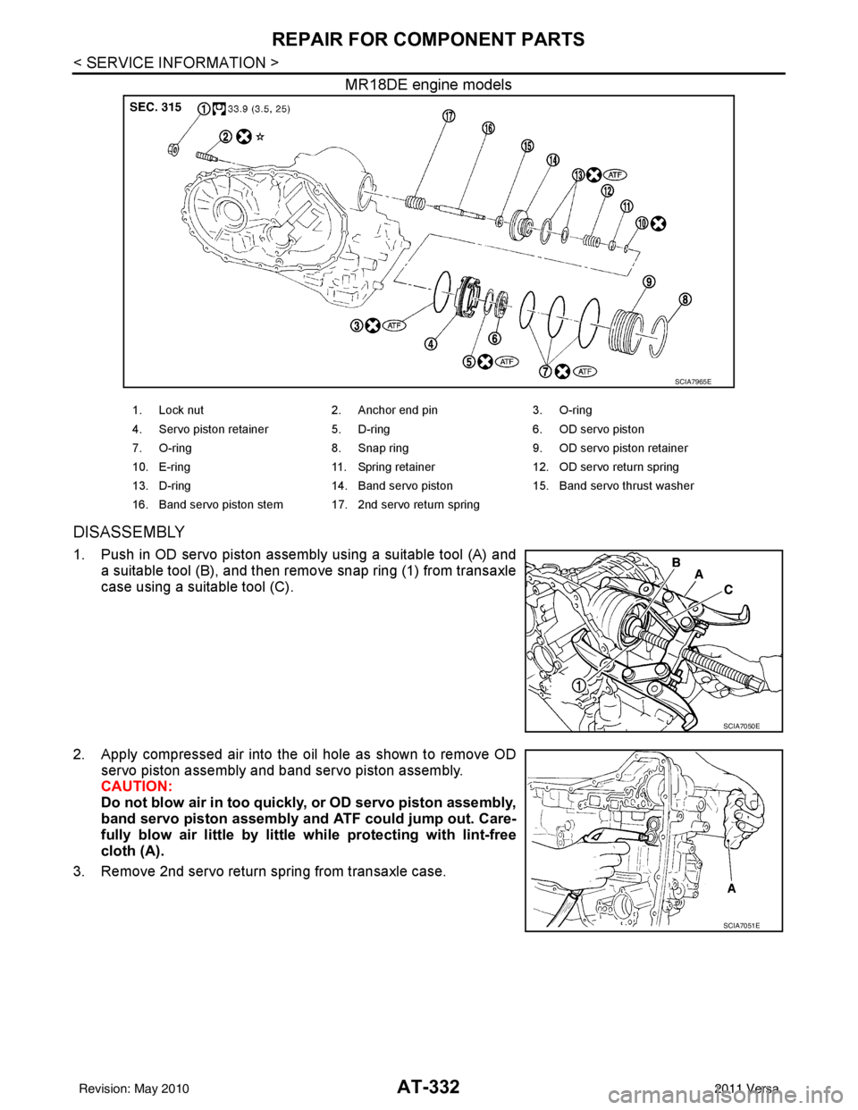
DISASSEMBLY
1. Push in OD servo piston assembly using a suitable tool (A) anda suitable tool (B), and then remove snap ring (1) from transaxle
case using a suitable tool (C).
2. Apply compressed air into the oil hole as shown to remove OD servo piston assembly and band servo piston assembly.
CAUTION:
Do not blow air in too quickly, or OD servo piston assembly,
band servo piston assembly and ATF could jump out. Care-
fully blow air little by little while protecting with lint-free
cloth (A).
3. Remove 2nd servo return spring from transaxle case.
SCIA7965E
1. Lock nut 2. Anchor end pin 3. O-ring
4. Servo piston retainer 5. D-ring 6. OD servo piston
7. O-ring 8. Snap ring 9. OD servo piston retainer
10. E-ring 11. Spring retainer 12. OD servo return spring
13. D-ring 14. Band servo piston 15. Band servo thrust washer
16. Band servo piston stem 17. 2nd servo return spring
SCIA7050E
SCIA7051E
Revision: May 2010 2011 Versa
Page 351 of 3787
AT-334
< SERVICE INFORMATION >
REPAIR FOR COMPONENT PARTS
9. Remove spring retainer (1), OD servo return spring (2), bandservo piston (3) and band servo thrust washer (4) from band
servo piston stem (5).
10. Remove O-ring from servo piston retainer.
a. HR16DE engine models (1): O-ring (small diameter)
(2): O-ring (large diameter)
(3): Servo piston retainer
b. MR18DE engine models (1): O-ring
(2): Servo piston retainer
11. Remove D-rings from band servo piston.
INSPECTION
Pistons, Retainers and Piston Stem
Check the sliding surfaces for damage or excessive wear. Replace if necessary.
Return Springs
SCIA7054E
JPDIA0258ZZ
SCIA7967E
SCIA3688E
Revision: May 2010 2011 Versa
Page 356 of 3787
REPAIR FOR COMPONENT PARTSAT-339
< SERVICE INFORMATION >
DE
F
G H
I
J
K L
M A
B
AT
N
O P
1. Remove final gear (1) from differential case (2).
2. Remove differential side bearings according to the following procedures.
a. HR16DE engine models
i. Set a suitable tool (A) on differential case (1), and remove differ- ential side bearing (RH side) (2) from differential case with suit-
able tool (B) and suitable tool (C).
ii. Set a suitable tool (A) on differential case (1), and remove differ- ential side bearing (LH side) (2) from differential case with suit-
able tool (B).
CAUTION:
Be careful not to mix up the right and left bearings.
b. MR18DE engine models
i. Set Tool on differential case, and remove differential side bear- ings from differential case using a suitable tool.
CAUTION:
Be careful not to mix up the right and left bearings.
SCIA8003E
SCIA7059E
SCIA7060E
Tool number : ST3306S001 (J-22888-D)
SAT312D
Revision: May 2010 2011 Versa
Page 366 of 3787

ASSEMBLYAT-349
< SERVICE INFORMATION >
DE
F
G H
I
J
K L
M A
B
AT
N
O P
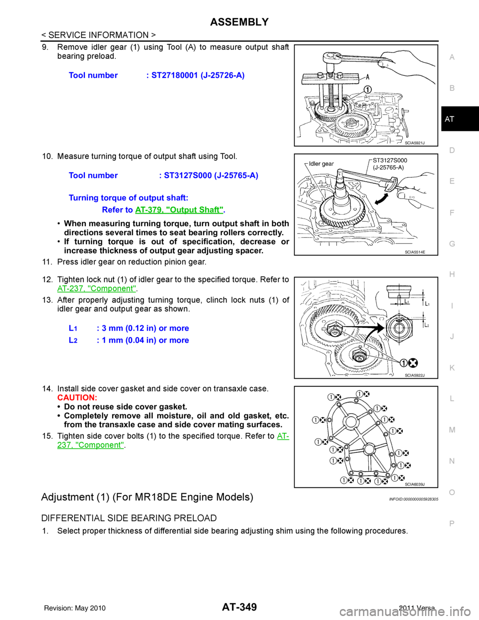
9. Remove idler gear (1) using Tool (A) to measure output shaft bearing preload.
10. Measure turning torque of output shaft using Tool. •When measuring turning torque , turn output shaft in both
directions several times to seat bearing rollers correctly.
• If turning torque is out of specification, decrease or
increase thickness of output gear adjusting spacer.
11. Press idler gear on reduction pinion gear.
12. Tighten lock nut (1) of idler gear to the specified torque. Refer to AT-237, "
Component".
13. After properly adjusting turning torque, clinch lock nuts (1) of idler gear and output gear as shown.
14. Install side cover gasket and side cover on transaxle case. CAUTION:
• Do not reuse side cover gasket.
• Completely remove all moistu re, oil and old gasket, etc.
from the transaxle case and side cover mating surfaces.
15. Tighten side cover bolts (1) to the specified torque. Refer to AT-
237, "Component".
Adjustment (1) (For MR18DE Engine Models)INFOID:0000000005928305
DIFFERENTIAL SIDE BEARING PRELOAD
1. Select proper thickness of differential side bearing adjusting shim using the following procedures.Tool number : ST27180001 (J-25726-A)
SCIA5921J
Tool number
: ST3127S000 (J-25765-A)
Turning torque of output shaft: Refer to AT-379, "
Output Shaft".
SCIA5514E
L1: 3 mm (0.12 in) or more
L
2: 1 mm (0.04 in) or more
SCIA5922J
SCIA6039J
Revision: May 2010 2011 Versa
Page 384 of 3787

ASSEMBLYAT-367
< SERVICE INFORMATION >
DE
F
G H
I
J
K L
M A
B
AT
N
O P
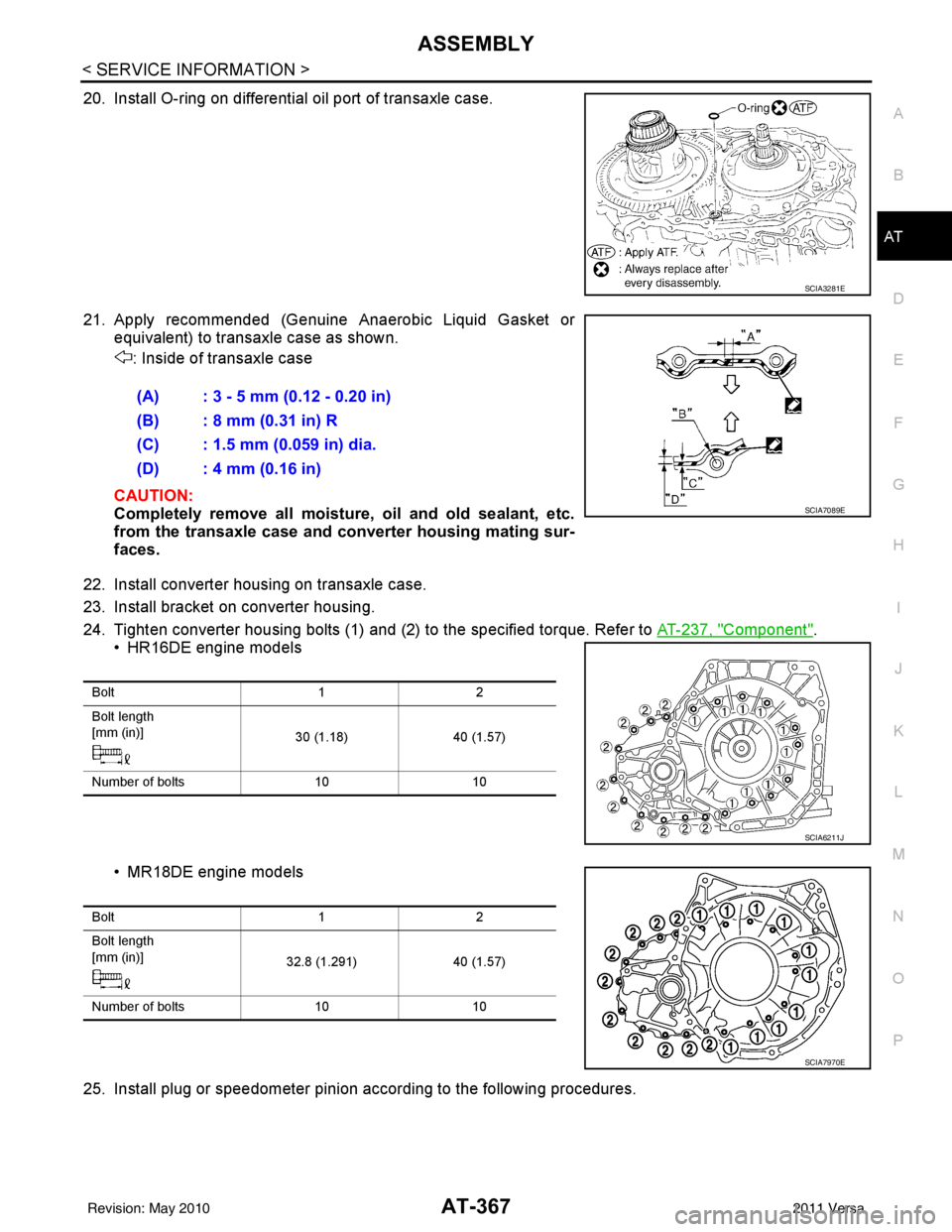
20. Install O-ring on differential oil port of transaxle case.
21. Apply recommended (Genuine Anaerobic Liquid Gasket or equivalent) to transaxle case as shown.
: Inside of transaxle case
CAUTION:
Completely remove all moisture, oil and old sealant, etc.
from the transaxle case and converter housing mating sur-
faces.
22. Install converter housing on transaxle case.
23. Install bracket on converter housing.
24. Tighten converter housing bolts (1) and (2) to the specified torque. Refer to AT-237, "
Component".
• HR16DE engine models
• MR18DE engine models
25. Install plug or speedometer pinion according to the following procedures.
SCIA3281E
(A) : 3 - 5 mm (0.12 - 0.20 in)
(B) : 8 mm (0.31 in) R
(C) : 1.5 mm (0.059 in) dia.
(D) : 4 mm (0.16 in)
SCIA7089E
Bolt 12
Bolt length
[mm (in)] 30 (1.18)40 (1.57)
Number of bolts 1010
SCIA6211J
Bolt 12
Bolt length
[mm (in)] 32.8 (1.291)40 (1.57)
Number of bolts 1010
SCIA7970E
Revision: May 2010 2011 Versa