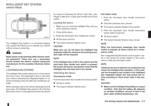
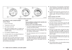
Page 65 of 235

REAR FOLDABLE TABLES
(where fitted)
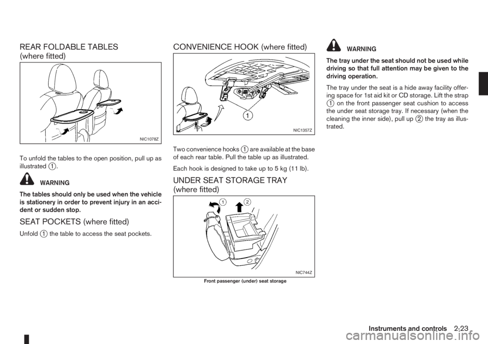
To unfold the tables to the open position, pull up as
illustratedj1.
WARNING
The tables should only be used when the vehicle
is stationery in order to prevent injury in an acci-
dent or sudden stop.
SEAT POCKETS (where fitted)
Unfoldj1 the table to access the seat pockets.
CONVENIENCE HOOK (where fitted)
Two convenience hooksj1 are available at the base
of each rear table. Pull the table up as illustrated.
Each hook is designed to take up to 5 kg (11 lb).
UNDER SEAT STORAGE TRAY
(where fitted)
WARNING
The tray under the seat should not be used while
driving so that full attention may be given to the
driving operation.
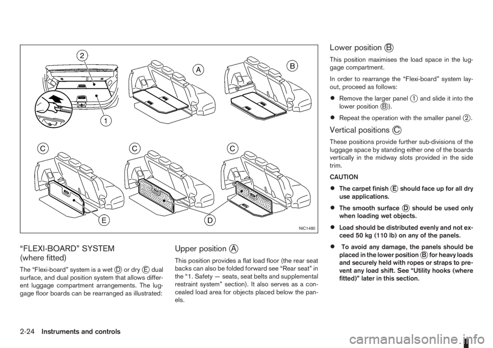
The tray under the seat is a hide away facility offer-
ing space for 1st aid kit or CD storage. Lift the strap
j1 on the front passenger seat cushion to access
the under seat storage tray. If necessary (when the
cleaning the inner side), pull up
j2 the tray as illus-
trated.
NIC1078Z
NIC1357Z
NIC744Z
Front passenger (under) seat storage
Instruments and controls2-23
Page 66 of 235

“FLEXI-BOARD” SYSTEM
(where fitted)
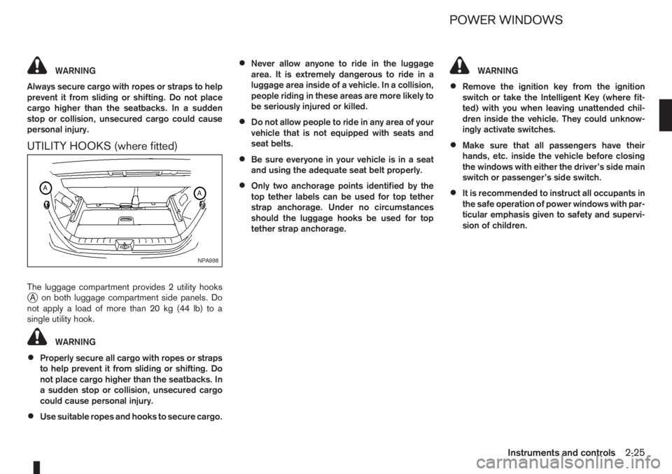
The “Flexi-board” system is a wetjDordryjE dual
surface, and dual position system that allows differ-
ent luggage compartment arrangements. The lug-
gage floor boards can be rearranged as illustrated:
Upper positionjA
This position provides a flat load floor (the rear seat
backs can also be folded forward see “Rear seat” in
the “1. Safety — seats, seat belts and supplemental
restraint system” section). It also serves as a con-
cealed load area for objects placed below the pan-
els.
Lower positionjB
This position maximises the load space in the lug-
gage compartment.
In order to rearrange the “Flexi-board” system lay-
out, proceed as follows:
•Remove the larger panelj1 and slide it into the
lower positionjB).
•Repeat the operation with the smaller panelj2.
Vertical positionsjC
These positions provide further sub-divisions of the
luggage space by standing either one of the boards
vertically in the midway slots provided in the side
trim.
CAUTION
•The carpet finishjE should face up for all dry
use applications.
•The smooth surfacejD should be used only
when loading wet objects.
•Load should be distributed evenly and not ex-
ceed 50 kg (110 lb) on any of the panels.
•To avoid any damage, the panels should be
placed in the lower positionjB for heavy loads
and securely held with ropes or straps to pre-
vent any load shift. See “Utility hooks (where
fitted)” later in this section.
NIC1480
2-24Instruments and controls
Page 67 of 235

WARNING
Always secure cargo with ropes or straps to help
prevent it from sliding or shifting. Do not place
cargo higher than the seatbacks. In a sudden
stop or collision, unsecured cargo could cause
personal injury.
UTILITY HOOKS (where fitted)
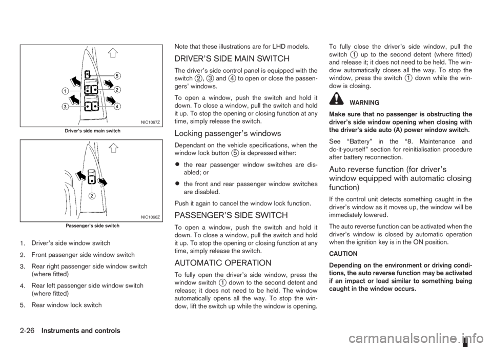
The luggage compartment provides 2 utility hooksjA on both luggage compartment side panels. Do
notapplyaloadofmorethan20kg(44lb)toa
single utility hook.
WARNING
•Properly secure all cargo with ropes or straps
to help prevent it from sliding or shifting. Do
not place cargo higher than the seatbacks. In
a sudden stop or collision, unsecured cargo
could cause personal injury.
•Use suitable ropes and hooks to secure cargo.
•Never allow anyone to ride in the luggage
area. It is extremely dangerous to ride in a
luggage area inside of a vehicle. In a collision,
people riding in these areas are more likely to
be seriously injured or killed.
•Do not allow people to ride in any area of your
vehicle that is not equipped with seats and
seat belts.
•Be sure everyone in your vehicle is in a seat
and using the adequate seat belt properly.
•Only two anchorage points identified by the
top tether labels can be used for top tether
strap anchorage. Under no circumstances
should the luggage hooks be used for top
tether strap anchorage.
WARNING
•Remove the ignition key from the ignition
switch or take the Intelligent Key (where fit-
ted) with you when leaving unattended chil-
dren inside the vehicle. They could unknow-
ingly activate switches.
•Make sure that all passengers have their
hands, etc. inside the vehicle before closing
the windows with either the driver’s side main
switch or passenger’s side switch.
•It is recommended to instruct all occupants in
the safe operation of power windows with par-
ticular emphasis given to safety and supervi-
sion of children.
NPA998
POWER WINDOWS
Instruments and controls2-25
Page 68 of 235

1.Driver’s side window switch
2.Front passenger side window switch
3.Rear right passenger side window switch
(where fitted)
4.Rear left passenger side window switch
(where fitted)
5.Rear window lock switchNote that these illustrations are for LHD models.
DRIVER’S SIDE MAIN SWITCH
The driver’s side control panel is equipped with the
switchj2,j3andj4 to open or close the passen-
gers’ windows.
To open a window, push the switch and hold it
down. To close a window, pull the switch and hold
it up. To stop the opening or closing function at any
time, simply release the switch.
Locking passenger’s windows
Dependant on the vehicle specifications, when the
window lock buttonj5 is depressed either:
•the rear passenger window switches are dis-
abled; or
•the front and rear passenger window switches
are disabled.
Push it again to cancel the window lock function.
PASSENGER’S SIDE SWITCH
To open a window, push the switch and hold it
down. To close a window, pull the switch and hold
it up. To stop the opening or closing function at any
time, simply release the switch.
AUTOMATIC OPERATION
To fully open the driver’s side window, press the
window switchj1 down to the second detent and
release; it does not need to be held. The window
automatically opens all the way. To stop the win-
dow, lift the switch up while the window is opening.To fully close the driver’s side window, pull the
switch
j1 up to the second detent (where fitted)
and release it; it does not need to be held. The win-
dow automatically closes all the way. To stop the
window, press the switch
j1 down while the win-
dow is closing.
WARNING
Make sure that no passenger is obstructing the
driver’s side window opening when closing with
the driver’s side auto (A) power window switch.
See “Battery” in the “8. Maintenance and
do-it-yourself” section for reinitialisation procedure
after battery reconnection.
Auto reverse function (for driver’s
window equipped with automatic closing
function)
If the control unit detects something caught in the
driver’s window as it moves up, the window will be
immediately lowered.
The auto reverse function can be activated when the
driver’s window is closed by automatic operation
when the ignition key is in the ON position.
CAUTION
Depending on the environment or driving condi-
tions, the auto reverse function may be activated
if an impact or load similar to something being
caught in the window occurs.
NIC1067Z
Driver’s side main switch
NIC1068Z
Passenger’s side switch
2-26Instruments and controls
Page 69 of 235
WARNING
There are some areas immediately before the
closed position where squeezing cannot be de-
tected. Be careful not to pinch your fingers.CAUTION
Do not use for extended periods of time with the
engine stopped. This could discharge the bat-
tery.
NOTE
The interior lights will go off after approximately
15 minutes unless the ignition switch is in the
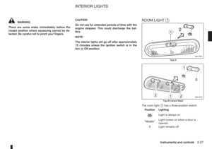
Acc or ON position.ROOM LIGHTj1
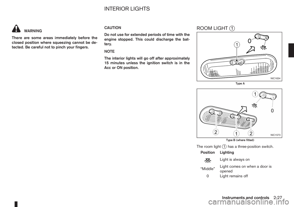
The room lightj1 has a three-position switch.
Position Lighting
mLightisalwayson
“Middle”Light comes on when a door is
opened
0 Light remains off
NIC1634
Type A
NIC1573
Type B (where fitted)
INTERIOR LIGHTS
Instruments and controls2-27
Page 70 of 235
Room light timer
The room light will stay on for approximately 30 sec-
onds when:
•The ignition is switched off.
•The doors are unlocked.
•Any door (except back door) is opened and then
closed.
The timer is cancelled, and the interior light will turn
off when:
•The doors are locked.
•The ignition switch is turned to the ON position.
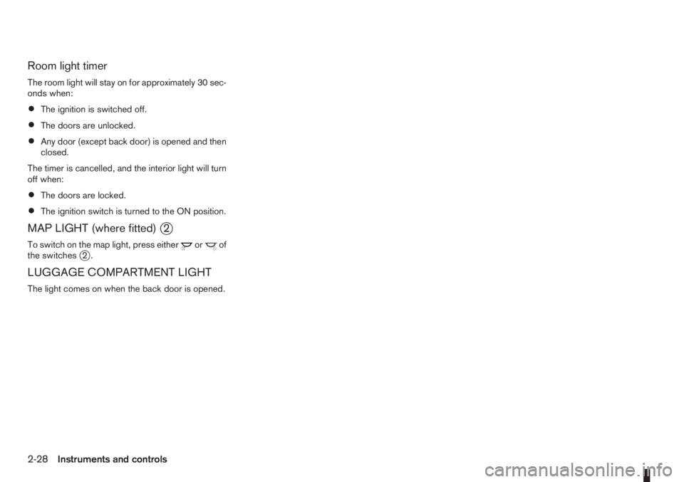
MAP LIGHT (where fitted)j2
To switch on the map light, press eitherorof
the switchesj2.
LUGGAGE COMPARTMENT LIGHT
The light comes on when the back door is opened.
2-28Instruments and controls
Page 71 of 235

3Pre-driving checks and adjustmentsPre-driving checks and adjustments
Keys ........................................................................ 3-2
Integrated keyfob/remote control system .................. 3-3
Using the remote keyless entry system ................ 3-3
Locking the doors ............................................... 3-3
Unlocking the doors – convenience mode ........... 3-4
Unlocking the doors – anti-hijack mode ............... 3-4
Switching from convenience mode to
anti-hijack mode.................................................. 3-4
Keyfob operation failure ...................................... 3-4
Intelligent Key system (where fitted) ......................... 3-5
Locking/unlocking .............................................. 3-5
Starting the engine with the Intelligent Key .......... 3-6
Door locks ............................................................... 3-6
Super Lock System (Right-hand drive models) .... 3-6
Vehicle dead battery – left-hand side door
handle ................................................................ 3-7
Locking with power door lock switch .................. 3-7Child safety rear door lock .................................. 3-8
Back door lock ................................................... 3-8
Security system ....................................................... 3-9
NISSAN Anti-Theft System (NATS)..................... 3-9
Bonnet release ........................................................ 3-10
Fuel filler lid ............................................................. 3-11
Fuel filler lid opener lever .................................... 3-11
Fuel filler cap ...................................................... 3-11
Handbrake lever ...................................................... 3-11
Tilting steering wheel ............................................... 3-12
Mirrors..................................................................... 3-12
Inside rear-view mirror ........................................ 3-12
Outside rear-view mirrors.................................... 3-12
Vanity mirror ....................................................... 3-13
Rear parcel shelf...................................................... 3-14
Rear parcel shelf removal.................................... 3-14
Rear parcel shelf installation................................ 3-14
Page 72 of 235

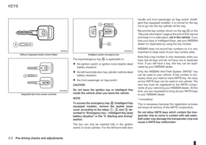
The key/emergency keyjB is applicable to:
•the ignition switch or ignition knob (keyfob dead
battery situation)
•the left-hand side door key cylinder (vehicle dead
battery situation)
•the front passenger air bag switch
CAUTION
Do not leave the ignition key or Intelligent Key
inside the vehicle when you leave the vehicle.
NOTE
To access the emergency key
jB (Intelligent Key
equipped models), remove the keyfob lower
cover according to the steps
j1,j2andj3 de-
scribed in “Emergency key – Intelligent Key dead
battery situation” in the “5. Starting and driving”
section.
The key can only be inserted fully in the ignition
switch or knob cylinder. For the left-hand side doorhandle and front passenger air bag switch (Intelli-
gent Key equipped models), it is normal for the key
not to go into the key cylinder all the way.
Record the key number shown on the tag
jA on the
“Security information” page at the end of this manual
and keep it in a safe place,not in the vehicle.Ifyou
lose your keys or Intelligent Keys, see your NISSAN
dealer for duplicates by using the key number.
NISSAN does not record key numbers so it is very
important to keep track of your key number plate.
Note that a key number is only necessary when you
have lost all keys and do not have one to duplicate
from. If you still have a key, this key can be dupli-
cated by your NISSAN dealer.
Only the NISSAN Anti-Theft System (NATS)* key
can be used on your vehicle. A key number is nec-
essary when you need an extra NATS key. As many
as four NATS keys can be used on one vehicle. The
new key must be registered to the NATS compo-
nents of your vehicle by your NISSAN dealer. At this
time, you are requested to bring all your NATS keys
to your NISSAN dealer.
* Immobilizer
This is necessary because the registration process
will erase all memory of the NATS components.
Do not allow NATS keys which contain the tran-
sponder chip to come in contact with salt water.
Salt water may damage the transponder chip and
cause a NATS key malfunction.
NPA958
Without integrated keyfob (where fitted)
NPA598Z
Integrated door lock remote controller
NPA599Z
Intelligent system emergency key
KEYS
3-2Pre-driving checks and adjustments