2011 NISSAN LATIO lock
[x] Cancel search: lockPage 77 of 3787
AT-60
< SERVICE INFORMATION >
TROUBLE DIAGNOSIS
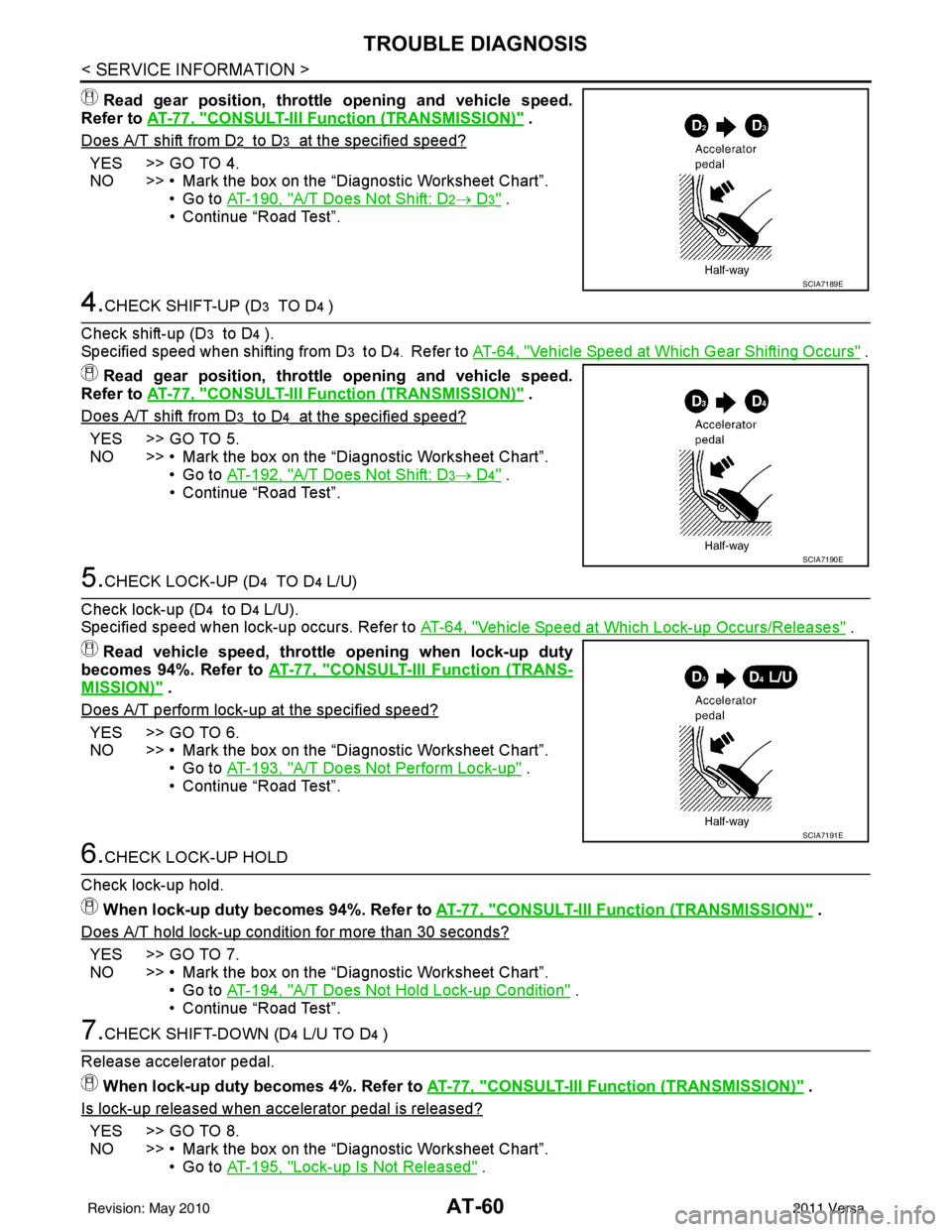
Read gear position, throttle opening and vehicle speed.
Refer to AT-77, "
CONSULT-III Function (TRANSMISSION)" .
Does A/T shift from D
2 to D3 at the specified speed?
YES >> GO TO 4.
NO >> • Mark the box on the “Diagnostic Worksheet Chart”. •Go to AT-190, "
A/T Does Not Shift: D2→ D3" .
• Continue “Road Test”.
4.CHECK SHIFT-UP (D3 TO D4 )
Check shift-up (D
3 to D4 ).
Specified speed when shifting from D
3 to D4. Refer to AT-64, "Vehicle Speed at Which Gear Shifting Occurs" .
Read gear position, throttle opening and vehicle speed.
Refer to AT-77, "
CONSULT-III Function (TRANSMISSION)" .
Does A/T shift from D
3 to D4 at the specified speed?
YES >> GO TO 5.
NO >> • Mark the box on the “Diagnostic Worksheet Chart”. •Go to AT-192, "
A/T Does Not Shift: D3→ D4" .
• Continue “Road Test”.
5.CHECK LOCK-UP (D4 TO D4 L/U)
Check lock-up (D
4 to D4 L/U).
Specified speed when lock-up occurs. Refer to AT-64, "
Vehicle Speed at Which Lock-up Occurs/Releases" .
Read vehicle speed, throttle opening when lock-up duty
becomes 94%. Refer to AT-77, "
CONSULT-III Function (TRANS-
MISSION)" .
Does A/T perform lock-up at the specified speed?
YES >> GO TO 6.
NO >> • Mark the box on the “Diagnostic Worksheet Chart”.
•Go to AT-193, "
A/T Does Not Perform Lock-up" .
• Continue “Road Test”.
6.CHECK LOCK-UP HOLD
Check lock-up hold. When lock-up duty becomes 94%. Refer to AT-77, "
CONSULT-III Function (TRANSMISSION)" .
Does A/T hold lock-up condition for more than 30 seconds?
YES >> GO TO 7.
NO >> • Mark the box on the “Diagnostic Worksheet Chart”. •Go to AT-194, "
A/T Does Not Hold Lock-up Condition" .
• Continue “Road Test”.
7.CHECK SHIFT-DOWN (D4 L/U TO D4 )
Release accelerator pedal. When lock-up duty becomes 4%. Refer to AT-77, "
CONSULT-III Function (TRANSMISSION)" .
Is lock-up released when accelerator pedal is released?
YES >> GO TO 8.
NO >> • Mark the box on the “Diagnostic Worksheet Chart”. •Go to AT-195, "
Lock-up Is Not Released" .
SCIA7189E
SCIA7190E
SCIA7191E
Revision: May 2010 2011 Versa
Page 81 of 3787
AT-64
< SERVICE INFORMATION >
TROUBLE DIAGNOSIS
Move selector lever from “2” to “1” position while driving in 22 .
Read gear position. Refer to AT-77, "
CONSULT-III Function
(TRANSMISSION)" .
Does A/T shift from 2
2 to 11 position?
YES >> GO TO 6.
NO >> • Mark the box on the “Diagnostic Worksheet Chart”. •Go to AT-199, "
A/T Does Not Shift: 22→ 11, When
Selector Lever "2" → "1" Position" .
• Continue “Road Test”.
6.CHECK ENGINE BRAKE
Check engine brake.
Does vehicle decelerate by engine brake?
YES >> 1. Stop vehicle. 2. Perform self-diagnosis. Refer to AT-77, "
CONSULT-
III Function (TRANSMISSION)" , AT-82, "Diagnosis
Procedure without CONSULT-III" .
NO >> • Mark the box on the “Diagnostic Worksheet Chart”. •Go to AT-201, "
Vehicle Does Not Decelerate by
Engine Brake" .
• Stop “Road Test”.
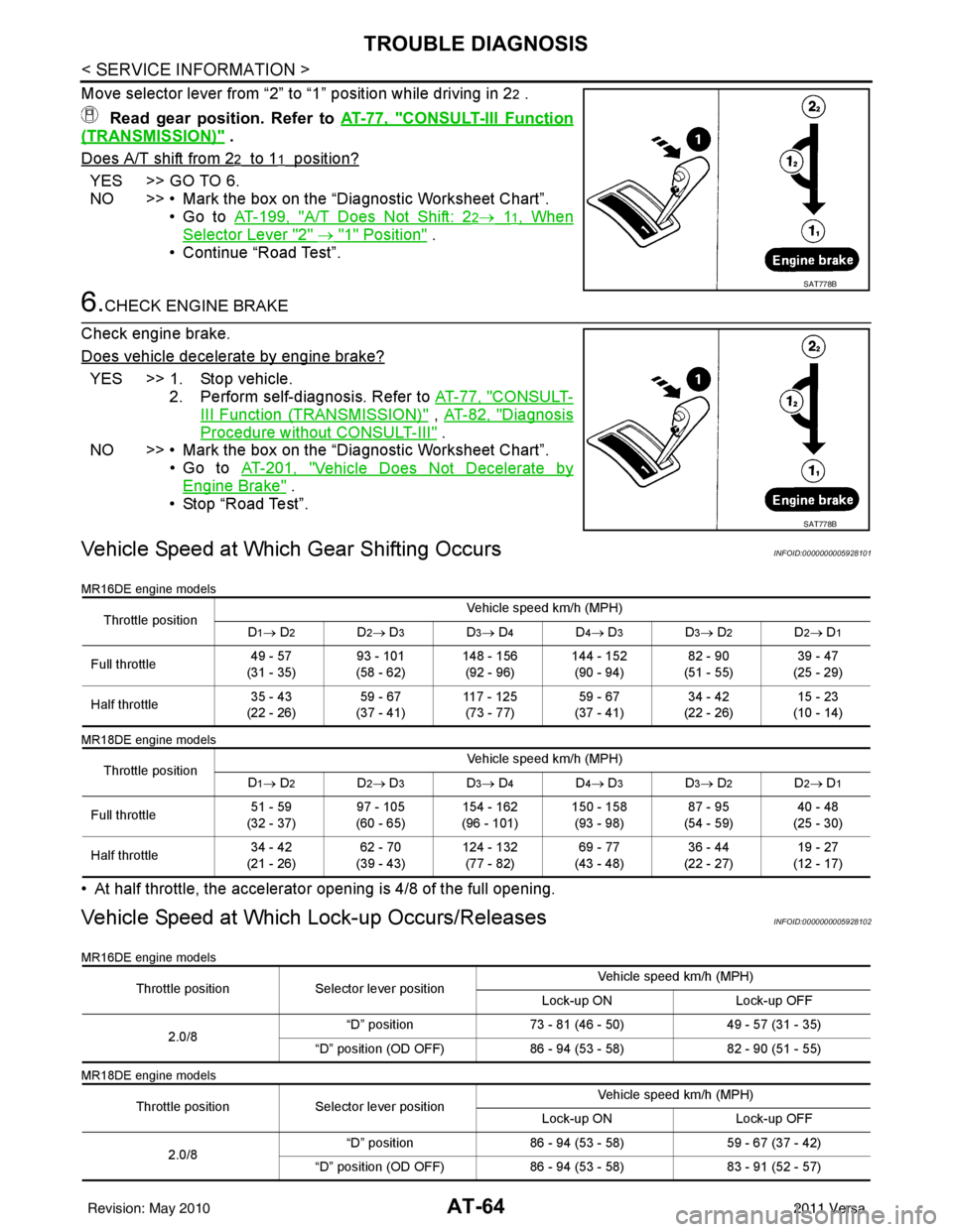
Vehicle Speed at Which Gear Shifting OccursINFOID:0000000005928101
MR16DE engine models
MR18DE engine models
• At half throttle, the accelerator opening is 4/8 of the full opening.
Vehicle Speed at Which Lock-up Occurs/ReleasesINFOID:0000000005928102
MR16DE engine models
MR18DE engine models
SAT778B
SAT778B
Throttle position Vehicle speed km/h (MPH)
D1→ D2D2→ D3D3→ D4D4→ D3D3→ D2D2→ D1
Full throttle 49 - 57
(31 - 35) 93 - 101
(58 - 62) 148 - 156
(92 - 96) 144 - 152
(90 - 94) 82 - 90
(51 - 55) 39 - 47
(25 - 29)
Half throttle 35 - 43
(22 - 26) 59 - 67
(37 - 41) 117 - 125
(73 - 77) 59 - 67
(37 - 41) 34 - 42
(22 - 26) 15 - 23
(10 - 14)
Throttle position Vehicle speed km/h (MPH)
D
1→ D2D2→ D3D3→ D4D4→ D3D3→ D2D2→ D1
Full throttle 51 - 59
(32 - 37) 97 - 105
(60 - 65) 154 - 162
(96 - 101) 150 - 158
(93 - 98) 87 - 95
(54 - 59) 40 - 48
(25 - 30)
Half throttle 34 - 42
(21 - 26) 62 - 70
(39 - 43) 124 - 132
(77 - 82) 69 - 77
(43 - 48) 36 - 44
(22 - 27) 19 - 27
(12 - 17)
Throttle position Selector lever position Vehicle speed km/h (MPH)
Lock-up ON Lock-up OFF
2.0/8 “D” position
73 - 81 (46 - 50) 49 - 57 (31 - 35)
“D” position (OD OFF) 86 - 94 (53 - 58)82 - 90 (51 - 55)
Throttle position Selector lever position Vehicle speed km/h (MPH)
Lock-up ON Lock-up OFF
2.0/8 “D” position
86 - 94 (53 - 58) 59 - 67 (37 - 42)
“D” position (OD OFF) 86 - 94 (53 - 58)83 - 91 (52 - 57)
Revision: May 2010 2011 Versa
Page 82 of 3787
TROUBLE DIAGNOSISAT-65
< SERVICE INFORMATION >
DE
F
G H
I
J
K L
M A
B
AT
N
O P
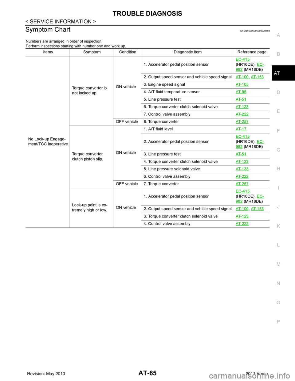
Symptom ChartINFOID:0000000005928103
Numbers are arranged in order of inspection.
Perform inspections starting with number one and work up.
Items Symptom Condition Diagnostic itemReference page
No Lock-up Engage-
ment/TCC Inoperative Torque converter is
not locked up.
ON vehicle1. Accelerator pedal position sensor
EC-415
(HR16DE), EC-
982 (MR18DE)
2. Output speed sensor and vehicle speed signal AT- 1 0 0
, AT- 1 5 3
3. Engine speed signalAT- 1 0 5
4. A/T fluid temperature sensorAT- 9 5
5. Line pressure testAT- 5 1
6. Torque converter clutch solenoid valveAT- 1 2 3
7. Control valve assemblyAT- 2 2 2
OFF vehicle 8. Torque converter AT- 2 5 7
Torque converter
clutch piston slip.ON vehicle1. A/T fluid level
AT- 1 7
2. Accelerator pedal position sensorEC-415
(HR16DE), EC-
982 (MR18DE)
3. Line pressure test AT- 5 1
4. Torque converter clutch solenoid valveAT- 1 2 3
5. Line pressure solenoid valveAT- 1 3 3
6. Control valve assemblyAT- 2 2 2
OFF vehicle 7. Torque converter AT- 2 5 7
Lock-up point is ex-
tremely high or low.ON vehicle1. Accelerator pedal position sensor
EC-415
(HR16DE), EC-
982 (MR18DE)
2. Output speed sensor and vehicle speed signal AT- 1 0 0
, AT- 1 5 3
3. Torque converter clutch solenoid valveAT- 1 2 3
4. Control valve assemblyAT- 2 2 2
Revision: May 2010 2011 Versa
Page 93 of 3787
AT-76
< SERVICE INFORMATION >
TROUBLE DIAGNOSIS
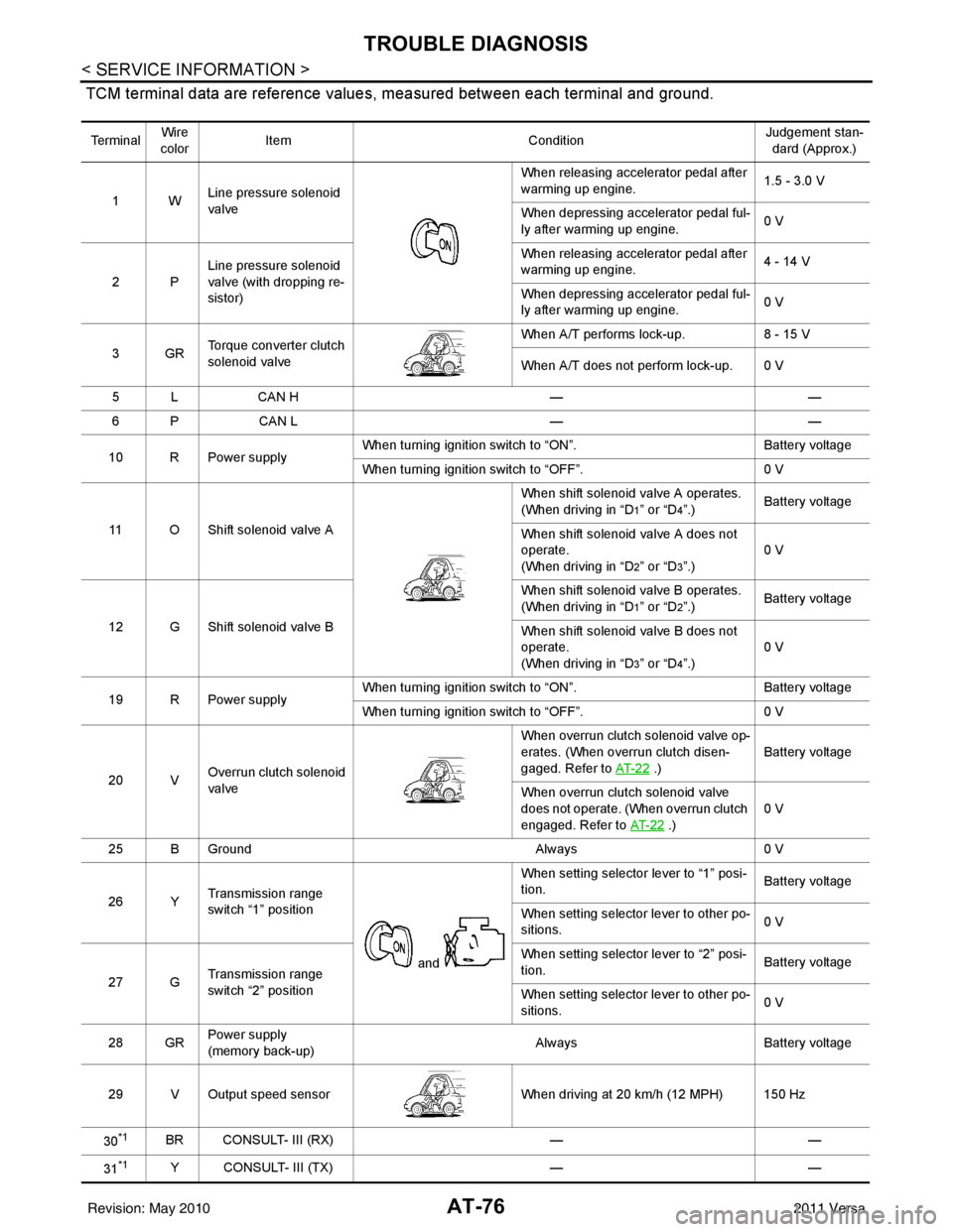
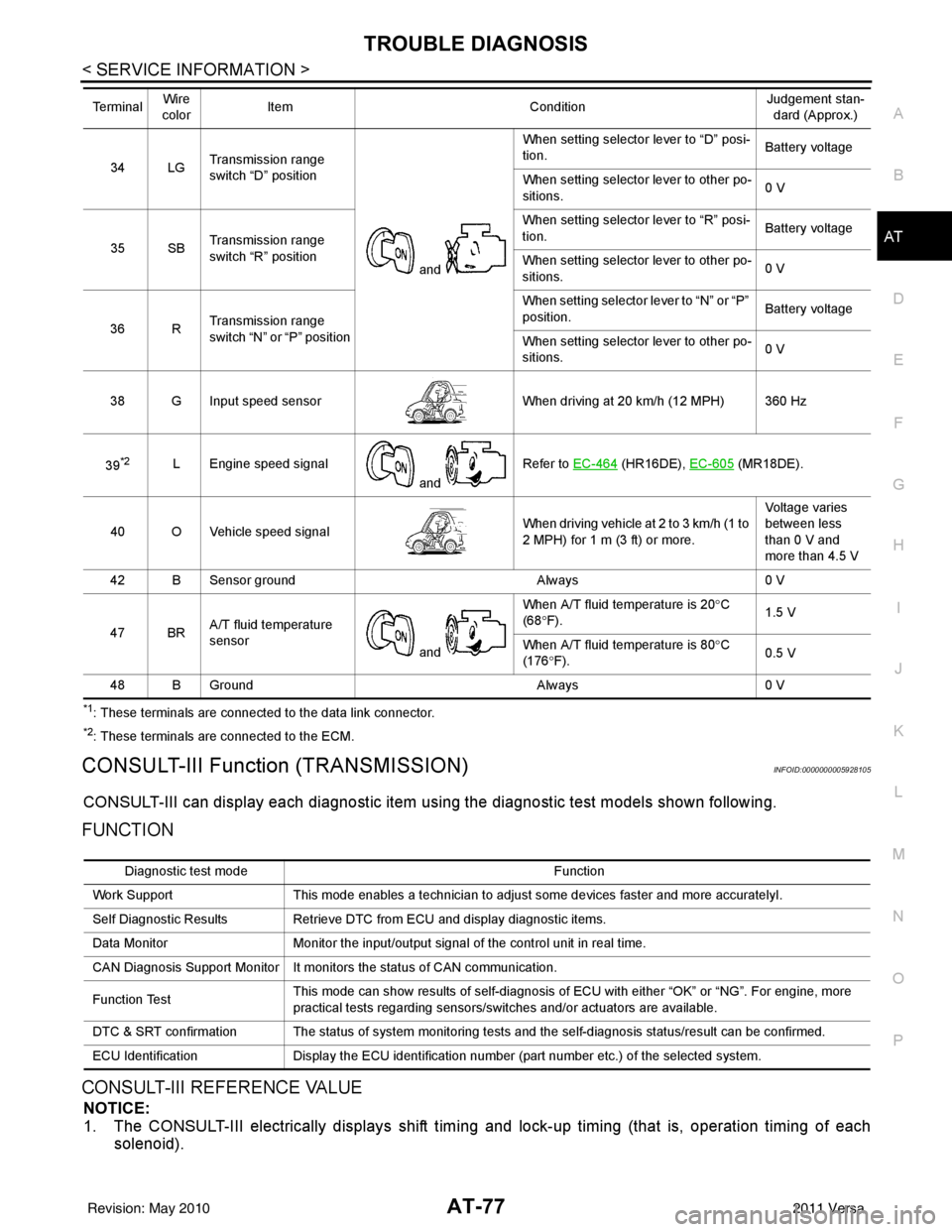
TCM terminal data are reference values, measured between each terminal and ground.
Te r m i n a lWire
color Item
ConditionJudgement stan-
dard (Approx.)
1W Line pressure solenoid
valve When releasing accelerator pedal after
warming up engine.
1.5 - 3.0 V
When depressing accelerator pedal ful-
ly after warming up engine. 0 V
2P Line pressure solenoid
valve (with dropping re-
sistor) When releasing accelerator pedal after
warming up engine.
4 - 14 V
When depressing accelerator pedal ful-
ly after warming up engine. 0 V
3GR Torque converter clutch
solenoid valve When A/T performs lock-up.
8 - 15 V
When A/T does not perform lock-up. 0 V
5 L CAN H ——
6 P CAN L ——
10 R Power supply When turning ignition switch to “ON”.
Battery voltage
When turning ignition switch to “OFF”. 0 V
11 O Shift solenoid valve A When shift solenoid valve A operates.
(When driving in “D
1” or “D4”.)
Battery voltage
When shift solenoid valve A does not
operate.
(When driving in “D
2” or “D3”.) 0 V
12 G Shift solenoid valve B When shift solenoid valve B operates.
(When driving in “D
1” or “D2”.)
Battery voltage
When shift solenoid valve B does not
operate.
(When driving in “D
3” or “D4”.) 0 V
19 R Power supply When turning ignition switch to “ON”.
Battery voltage
When turning ignition switch to “OFF”. 0 V
20 V Overrun clutch solenoid
valve When overrun clutch solenoid valve op-
erates. (When overrun clutch disen-
gaged. Refer to
AT- 2 2
.) Battery voltage
When overrun clutch solenoid valve
does not operate. (When overrun clutch
engaged. Refer to AT- 2 2
.)0 V
25 B Ground Always0 V
26 Y Transmission range
switch “1” position
and When setting selector lever to “1” posi-
tion.
Battery voltage
When setting selector lever to other po-
sitions. 0 V
27 G Transmission range
switch “2” position When setting selector lever to “2” posi-
tion.
Battery voltage
When setting selector lever to other po-
sitions. 0 V
28 GR Power supply
(memory back-up) Always
Battery voltage
29 V Output speed sensor When driving at 20 km/h (12 MPH) 150 Hz
30
*1BR CONSULT- III (RX) ——
31
*1Y CONSULT- III (TX) ——
Revision: May 2010 2011 Versa
Page 94 of 3787
TROUBLE DIAGNOSISAT-77
< SERVICE INFORMATION >
DE
F
G H
I
J
K L
M A
B
AT
N
O P
*1: These terminals are connected to the data link connector.
*2: These terminals are connected to the ECM.
CONSULT-III Function (TRANSMISSION)INFOID:0000000005928105
CONSULT-III can display each diagnostic item using the diagnostic test models shown following.
FUNCTION
CONSULT-III REFERENCE VALUE
NOTICE:
1. The CONSULT-III electrically displays shift timi ng and lock-up timing (that is, operation timing of each
solenoid).
34 LG Transmission range
switch “D” position
and When setting selector lever to “D” posi-
tion.
Battery voltage
When setting selector lever to other po-
sitions. 0 V
35 SB Transmission range
switch “R” position When setting selector lever to “R” posi-
tion.
Battery voltage
When setting selector lever to other po-
sitions. 0 V
36 R Transmission range
switch “N” or “P” position When setting selector
lever to “N” or “P”
position. Battery voltage
When setting selector lever to other po-
sitions. 0 V
38 G Input speed sensor When driving at 20 km/h (12 MPH) 360 Hz
39
*2L Engine speed signal and Refer to EC-464 (HR16DE),
EC-605 (MR18DE).
40 O Vehicle speed signal When driving vehicle at 2 to 3 km/h (1 to
2 MPH) for 1 m (3 ft) or more.Voltage varies
between less
than 0 V and
more than 4.5 V
42 B Sensor ground Always0 V
47 BR A/T fluid temperature
sensor
and When A/T fluid temperature is 20°
C
(68 °F). 1.5 V
When A/T fluid temperature is 80° C
(176 °F). 0.5 V
48 B Ground Always0 V
Te r m i n a l
Wire
color Item
ConditionJudgement stan-
dard (Approx.)
Diagnostic test mode Function
Work Support This mode enables a technician to adjust some devices faster and more accuratelyI.
Self Diagnostic Results Retrieve DTC from ECU and display diagnostic items.
Data Monitor Monitor the input/output signal of the control unit in real time.
CAN Diagnosis Support Monitor It monitors the status of CAN communication.
Function Test This mode can show results of self-diagnosis of ECU with either “OK” or “NG”. For engine, more
practical tests regarding sensors/switches and/or actuators are available.
DTC & SRT confirmation The status of system monitoring tests and the self-diagnosis status/result can be confirmed.
ECU Identification Display the ECU identification number (part number etc.) of the selected system.
Revision: May 2010 2011 Versa
Page 95 of 3787

AT-78
< SERVICE INFORMATION >
TROUBLE DIAGNOSIS
Check for time difference between actual shift timing and the CONSULT-III display. If the difference is
noticeable, mechanical parts (except solenoids, sens ors, etc.) may be malfunctioning. Check mechanical
parts using applicable diagnostic procedures.
2. Shift schedule (which implies gear position) display ed on CONSULT-III and that indicated in Service Man-
ual may differ slightly. This occurs because of the following reasons:
- Actual shift schedule has more or less tolerance or allowance,
- Shift schedule indicated in Service Manual refers to the point where shifts start, and
- Gear position displayed on CONSULT-III indicates the point where shifts are completed.
3. Shift solenoid valve “A” or “B” is displayed on CONSUL T-III at the start of shifting. Gear position is dis-
played upon completion of shifting (which is computed by TCM).
Item name Condition Display value (Approx.)
VHCL/S SE-A/T During driving Approximately matches the speedometer
reading.
VHCL/S SE-MTR
THROTTLE POSI Released accelerator pedal.
0.0/8
Fully depressed accelerator pedal. 8.0/8
FLUID TEMP SE When A/T fluid temperature is 20
°C (68 °F). 1.5 V
When A/T fluid temperature is 80 °C (176 °F). 0.5 V
BATTERY VOLT When turning ignition switch to “ON”. Battery voltage
ENGINE SPEED Engine running Approximately matches the tachometer
reading.
INPUT SPEED During driving (lock-up ON) Approximately matche s the engine speed.
OVERDRIVE SW When overdrive control switch is depressed. ON
When overdrive control switch is released. OFF
PN POSI SW When setting selector lever
to “N” or “P” position. ON
When setting selector lever to other positions. OFF
R POSITION SW When setting selector lever to “R” position. ON
When setting selector lever to other positions. OFF
D POSITION SW When setting selector lever to “D” position. ON
When setting selector lever to other positions. OFF
2 POSITION SW When setting selector lever to “2” position. ON
When setting selector lever to other positions. OFF
1 POSITION SW When setting selector lever to “1” position. ON
When setting selector lever to other positions. OFF
CLOSED THL/SW Released accelerator pedal.
ON
Depressed accelerator pedal. OFF
W/O THRL/P-SW Fully depressed accelerator pedal.
ON
Released accelerator pedal. OFF
SHIFT S/V A When shift solenoid valve A operates.
(When driving in “D
1” or “D4”.)
ON
When shift solenoid valve A does not operate.
(When driving in “D
2” or “D3”.) OFF
SHIFT S/V B When shift solenoid valve B operates.
(When driving in “D
1” or “D2”.)
ON
When shift solenoid valve B does not operate.
(When driving in “D
3” or “D4”.) OFF
Revision: May 2010
2011 Versa
Page 96 of 3787
TROUBLE DIAGNOSISAT-79
< SERVICE INFORMATION >
DE
F
G H
I
J
K L
M A
B
AT
N
O P
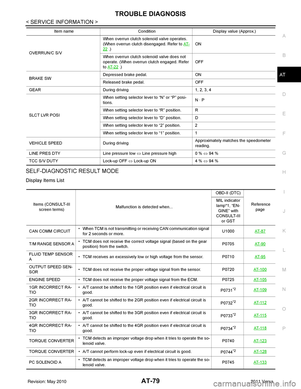
SELF-DIAGNOSTIC RESULT MODE
Display Items List
OVERRUN/C S/V When overrun clutch solenoid valve operates.
(When overrun clutch disengaged. Refer to
AT-22 .) ON
When overrun clutch solenoid valve does not
operate. (When overrun clutch engaged. Refer
to AT- 2 2
.) OFF
BRAKE SW Depressed brake pedal.
ON
Released brake pedal. OFF
GEAR During driving 1, 2, 3, 4
SLCT LVR POSI When setting selector lever to “N” or “P” posi-
tions.
N · P
When setting selector lever to “R” position. R
When setting selector lever to “D” position. D
When setting selector lever to “2” position. 2
When setting selector lever to “1” position. 1
VEHICLE SPEED During driving Approximately matches the speedometer
reading.
LINE PRES DTY Line pressure low ⇔ Line pressure high 0 % ⇔ 94 %
TCC S/V DUTY Lock-up OFF ⇔ Lock-up ON 4 % ⇔ 94 %
Item name
Condition Display value (Approx.)
Items (CONSULT-III
screen terms) Malfunction is detected when... OBD-II (DTC)
Reference page
MIL indicator
lamp*1, “EN-
GINE” with
CONSULT-III
or GST
CAN COMM CIRCUIT • When TCM is not transmitting or receiving CAN communication signal
for 2 seconds or more. U1000
AT- 8 7
T/M RANGE SENSOR A • TCM does not receive the correct voltage signal (based on the gear
position) from the switch. P0705
AT- 9 0
FLUID TEMP SENSOR
A • TCM receives an excessively low or high voltage from the sensor. P0710
AT- 9 5
OUTPUT SPEED SEN-
SOR• TCM does not receive the proper voltage signal from the sensor.
P0720AT- 1 0 0
ENGINE SPEED • TCM does not re ceive the proper voltage signal from the ECM. P0725AT- 1 0 5
1GR INCORRECT RA-
TIO • A/T cannot be shifted to the 1GR position even if electrical circuit is
good. P0731*2AT- 1 0 9
2GR INCORRECT RA-
TIO• A/T cannot be shifted to the 2GR position even if electrical circuit is
good. P0732*2AT- 11 2
3GR INCORRECT RA-
TIO• A/T cannot be shifted to the 3GR position even if electrical circuit is
good. P0733*2AT- 11 5
4GR INCORRECT RA-
TIO• A/T cannot be shifted to the 4GR position even if electrical circuit is
good. P0734*2AT- 11 8
TORQUE CONVERTER• TCM detects an improper voltage drop when it tries to operate the so-
lenoid valve. P0740
AT- 1 2 3
TORQUE CONVERTER • A/T cannot perform lock-up even if electrical circuit is good.
P0744*2AT- 1 2 8
PC SOLENOID A• TCM detects an improper voltage drop when it tries to operate the so-
lenoid valve. P0745
AT- 1 3 3
Revision: May 2010 2011 Versa
Page 100 of 3787
TROUBLE DIAGNOSISAT-83
< SERVICE INFORMATION >
DE
F
G H
I
J
K L
M A
B
AT
N
O P
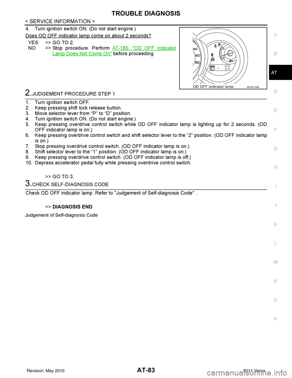
4. Turn ignition switch ON. (Do not start engine.)
Does OD OFF indicator lamp come on about 2 seconds?
YES >> GO TO 2.
NO >> Stop procedure. Perform AT-180, "
OD OFF Indicator
Lamp Does Not Come On" before proceeding.
2.JUDGEMENT PROCEDURE STEP 1
1. Turn ignition switch OFF.
2. Keep pressing shift lock release button.
3. Move selector lever from “P” to “D” position.
4. Turn ignition switch ON. (Do not start engine.)
5. Keep pressing overdrive control switch while OD OFF indicator lamp is lighting up for 2 seconds. (OD OFF indicator lamp is on.)
6. Keep pressing overdrive control swit ch and shift selector lever to the “2” position. (OD OFF indicator lamp
is on.)
7. Stop pressing overdrive control switch. (OD OFF indicator lamp is on.)
8. Shift selector lever to the “1” position. (OD OFF indicator lamp is on.)
9. Keep pressing overdrive control switch . (OD OFF indicator lamp is off.)
10. Depress accelerator pedal fully while pressing overdrive control switch.
>> GO TO 3.
3.CHECK SELF-DIAGNOSIS CODE
Check OD OFF indicator lamp. Refer to "Judgement of Self-diagnosis Code" .
>>DIAGNOSIS END
Judgement of Self-diagnosis Code
SCIA7140E
Revision: May 2010 2011 Versa