2011 NISSAN LATIO brake
[x] Cancel search: brakePage 619 of 3787

INTELLIGENT KEY SYSTEMBL-109
< SERVICE INFORMATION >
C
DE
F
G H
J
K L
M A
B
BL
N
O P
17 W Rear bumper antenna
(+) signal
LOCK Press back door request switch.
18 B Rear bumper antenna
(-) signal
19 V Front outside antenna
LH (+) signal
LOCK Press door request switch LH.
20 P Front outside antenna
LH (-) signal
22
*2BR Key interlock solenoid — With Intelligent Key present or mechanical
key in ignition cylinder, press "PUSH" but-
ton on ignition cylinder.
Battery voltage
Other than above 0
23 LG Back door open output — Back door open (switch closed)
0
Back door closed (switch open) 5
24 V Back door opener
switch —Press and hold back door switch.
0
Other than above 5
25 L Front door request
switch RH —Press front door request switch RH.
0
Other than above 5
26 SB Stop lamp switch —Depress brake pedal
Battery voltage
Other than above 0
27 W Ignition knob switch — Press ignition switch.
Battery voltage
Release ignition switch. 0
28 Y Unlock sensor
(driver side) —Door (driver si
de) is locked. 5
Door (driver side ) is unlocked. 0
29 V Back door request
switch (hatchback)
—Press back door request switch.
0
Other than above 5
Trunk opener request
switch (sedan) —Press trunk opener request switch.
0
Other than above 5
31 BR Steering lock solenoid
ground
——
0
32 GR Steering lock solenoid
communication signal LOCKWhen Intelligent Key is inside vehicle,
press ignition knob switch.
Other than above
5
Terminal
Wire
Color Item Condition
Voltage (V)Approx.
Ignition
Switch
Position Operation or Conditions
SIIA1910J
SIIA1910J
SIIA1911J
Revision: May 2010
2011 Versa
Page 661 of 3787
INTELLIGENT KEY SYSTEMBL-151
< SERVICE INFORMATION >
C
DE
F
G H
J
K L
M A
B
BL
N
O P
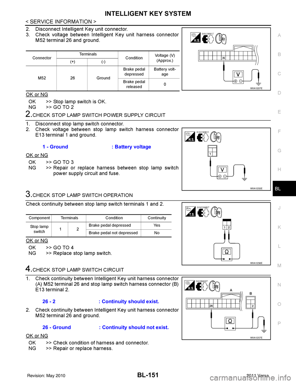
2. Disconnect Intelligent Key unit connector.
3. Check voltage between Intelligent Key unit harness connector M52 terminal 26 and ground.
OK or NG
OK >> Stop lamp switch is OK.
NG >> GO TO 2
2.CHECK STOP LAMP SWIT CH POWER SUPPLY CIRCUIT
1. Disconnect stop lamp switch connector.
2. Check voltage between stop lamp switch harness connector E13 terminal 1 and ground.
OK or NG
OK >> GO TO 3
NG >> Repair or replace harness between stop lamp switch power supply circuit and fuse.
3.CHECK STOP LAMP SWITCH OPERATION
Check continuity between stop lamp switch terminals 1 and 2.
OK or NG
OK >> GO TO 4
NG >> Replace stop lamp switch.
4.CHECK STOP LAMP SWITCH CIRCUIT
1. Check continuity between Intelligent Key unit harness connector (A) M52 terminal 26 and stop lamp switch harness connector (B)
E13 terminal 2.
2. Check continuity between Intelligent Key unit harness connector M52 terminal 26 and ground.
OK or NG
OK >> Check condition of harness and connector.
NG >> Repair or replace harness.
Connector Te r m i n a l s
ConditionVoltage (V)
(Approx.)
(+) (-)
M52 26Ground Brake pedal
depressed Battery volt-
age
Brake pedal released 0
WIIA1207E
1 - Ground
: Battery voltage
WIIA1255E
Component Terminals ConditionContinuity
Stop lamp switch 12 Brake pedal depressed
Yes
Brake pedal not depressed No
WIIA1256E
26 - 2 : Continuity should exist.
26 - Ground : Continuity should not exist.
WIIA1257E
Revision: May 2010 2011 Versa
Page 662 of 3787
BL-152
< SERVICE INFORMATION >
INTELLIGENT KEY SYSTEM
Stop Lamp Switch Check (With M/T)
INFOID:0000000005929360
1.CHECK STOP LAMP SWITCH INPUT SIGNAL
1. Turn ignition switch OFF.
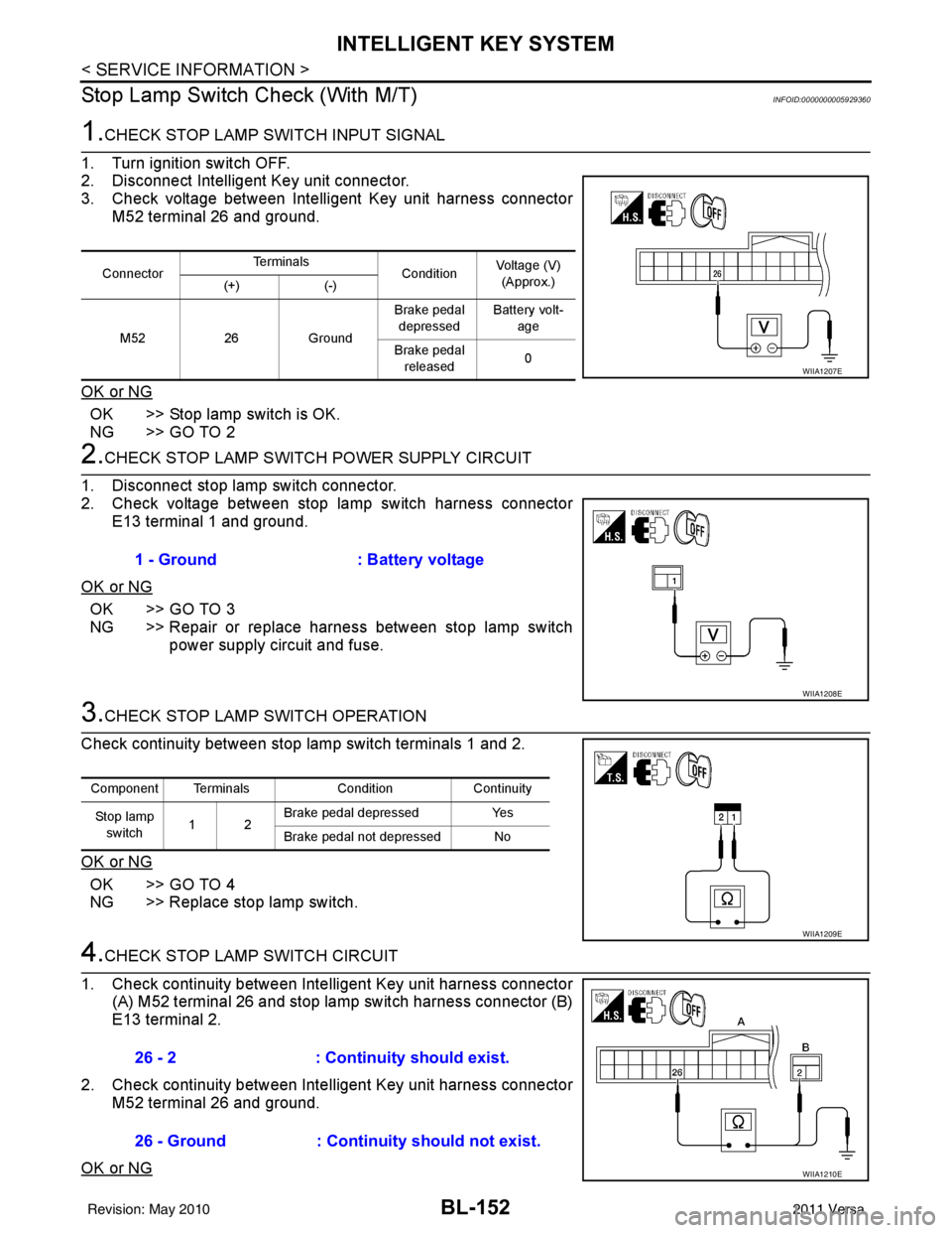
2. Disconnect Intelligent Key unit connector.
3. Check voltage between Intelligent Key unit harness connector M52 terminal 26 and ground.
OK or NG
OK >> Stop lamp switch is OK.
NG >> GO TO 2
2.CHECK STOP LAMP SWIT CH POWER SUPPLY CIRCUIT
1. Disconnect stop lamp switch connector.
2. Check voltage between stop lamp switch harness connector E13 terminal 1 and ground.
OK or NG
OK >> GO TO 3
NG >> Repair or replace harness between stop lamp switch power supply circuit and fuse.
3.CHECK STOP LAMP SWITCH OPERATION
Check continuity between stop lamp switch terminals 1 and 2.
OK or NG
OK >> GO TO 4
NG >> Replace stop lamp switch.
4.CHECK STOP LAMP SWITCH CIRCUIT
1. Check continuity between Inte lligent Key unit harness connector
(A) M52 terminal 26 and stop lamp switch harness connector (B)
E13 terminal 2.
2. Check continuity between Inte lligent Key unit harness connector
M52 terminal 26 and ground.
OK or NG
Connector Te r m i n a l s
ConditionVoltage (V)
(Approx.)
(+) (-)
M52 26Ground Brake pedal
depressed Battery volt-
age
Brake pedal released 0
WIIA1207E
1 - Ground
: Battery voltage
WIIA1208E
Component Terminals ConditionContinuity
St op la mp switch 12 Brake pedal depressed
Yes
Brake pedal not depressed No
WIIA1209E
26 - 2 : Continuity should exist.
26 - Ground : Continuity should not exist.
WIIA1210E
Revision: May 2010 2011 Versa
Page 691 of 3787
BACK DOOR LOCKBL-181
< SERVICE INFORMATION >
C
DE
F
G H
J
K L
M A
B
BL
N
O P
10*1W CVT or A/T shift selec-
tor (park position
switch)
ONShift lever in park position.
0
Other than above Battery voltage
11 SB Power source (Fus e) — —Battery voltage
12 B Ground —— 0
13 V Instrument panel an-
tenna (+) signal
LOCK• Any door open
→ all door close
• Press ignition knob switch: ON (Ignition knob switch)
14 LG Instrument panel an-
tenna (-) signal
15 L Front console antenna
(+) signal
LOCK• Any door open
→ all door close
• Press ignition knob switch: ON (Ignition knob switch)
16 P Front console antenna
(-) signal
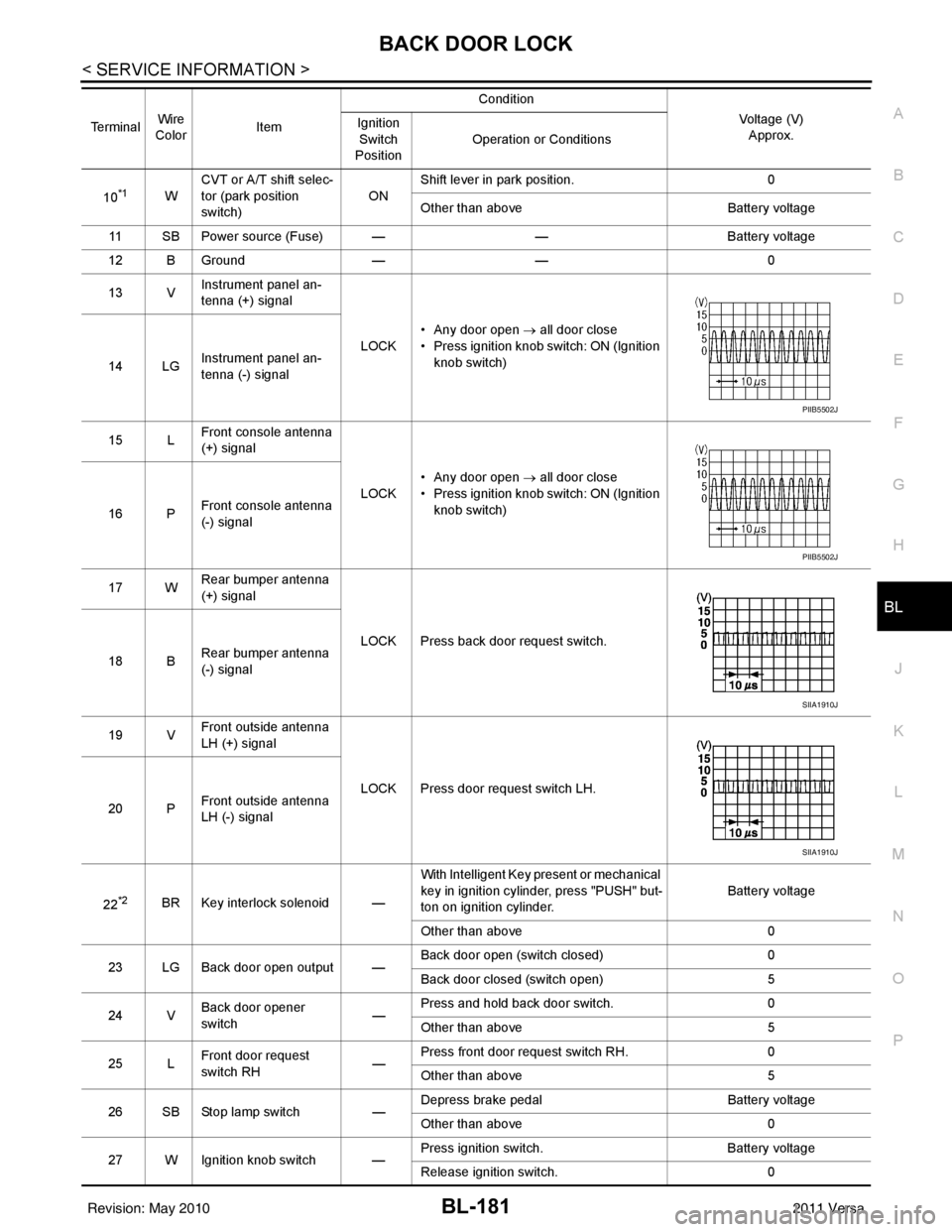
17 W Rear bumper antenna
(+) signal
LOCK Press back door request switch.
18 B Rear bumper antenna
(-) signal
19 V Front outside antenna
LH (+) signal
LOCK Press door request switch LH.
20 P Front outside antenna
LH (-) signal
22
*2BR Key interlock solenoid — With Intelligent Key present or mechanical
key in ignition cylinder, press "PUSH" but-
ton on ignition cylinder.
Battery voltage
Other than above 0
23 LG Back door open output — Back door open (switch closed)
0
Back door closed (switch open) 5
24 V Back door opener
switch —Press and hold back door switch.
0
Other than above 5
25 L Front door request
switch RH
—Press front door request switch RH.
0
Other than above 5
26 SB Stop lamp switch —Depress brake pedal
Battery voltage
Other than above 0
27 W Ignition knob switch — Press ignition switch.
Battery voltage
Release ignition switch. 0
Terminal
Wire
Color Item Condition
Voltage (V)Approx.
Ignition
Switch
Position Operation or Conditions
PIIB5502J
PIIB5502J
SIIA1910J
SIIA1910J
Revision: May 2010
2011 Versa
Page 716 of 3787
BL-206
< SERVICE INFORMATION >
TRUNK LID OPENER
10*1WCVT or A/T shift selec-
tor (park position
switch)
ONShift lever in park position.
0
Other than above Battery voltage
11 SB Power source (Fuse) — —Battery voltage
12 B Ground —— 0
13 V Instrument panel an-
tenna (+) signal
LOCK• Any door open
→ all door close
• Press ignition knob switch: ON (Ignition knob switch)
14 LG Instrument panel an-
tenna (-) signal
15 L Front console antenna
(+) signal
LOCK• Any door open
→ all door close
• Press ignition knob switch: ON (Ignition knob switch)
16 P Front console antenna
(-) signal
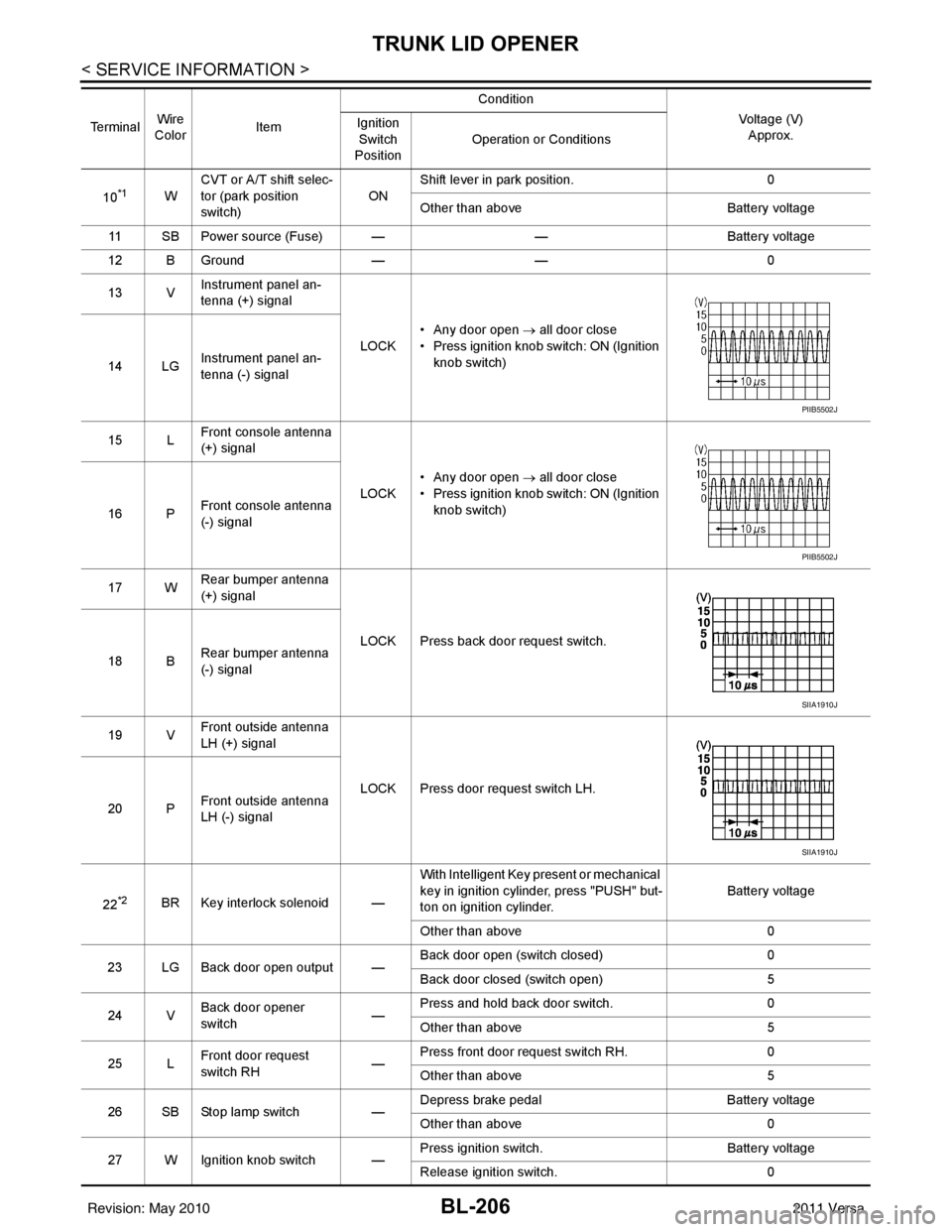
17 W Rear bumper antenna
(+) signal
LOCK Press back door request switch.
18 B Rear bumper antenna
(-) signal
19 V Front outside antenna
LH (+) signal
LOCK Press door request switch LH.
20 P Front outside antenna
LH (-) signal
22
*2BR Key interlock solenoid — With Intelligent Key present or mechanical
key in ignition cylinder, press "PUSH" but-
ton on ignition cylinder.
Battery voltage
Other than above 0
23 LG Back door open output — Back door open (switch closed)
0
Back door closed (switch open) 5
24 V Back door opener
switch —Press and hold back door switch.
0
Other than above 5
25 L Front door request
switch RH
—Press front door request switch RH.
0
Other than above 5
26 SB Stop lamp switch —Depress brake pedal
Battery voltage
Other than above 0
27 W Ignition knob switch — Press ignition switch.
Battery voltage
Release ignition switch. 0
Te r m i n a l
Wire
Color Item Condition
Voltage (V)Approx.
Ignition
Switch
Position Operation or Conditions
PIIB5502J
PIIB5502J
SIIA1910J
SIIA1910J
Revision: May 2010
2011 Versa
Page 741 of 3787
VEHICLE SECURITY (THEFT WARNING) SYSTEMBL-231
< SERVICE INFORMATION >
C
DE
F
G H
J
K L
M A
B
BL
N
O P
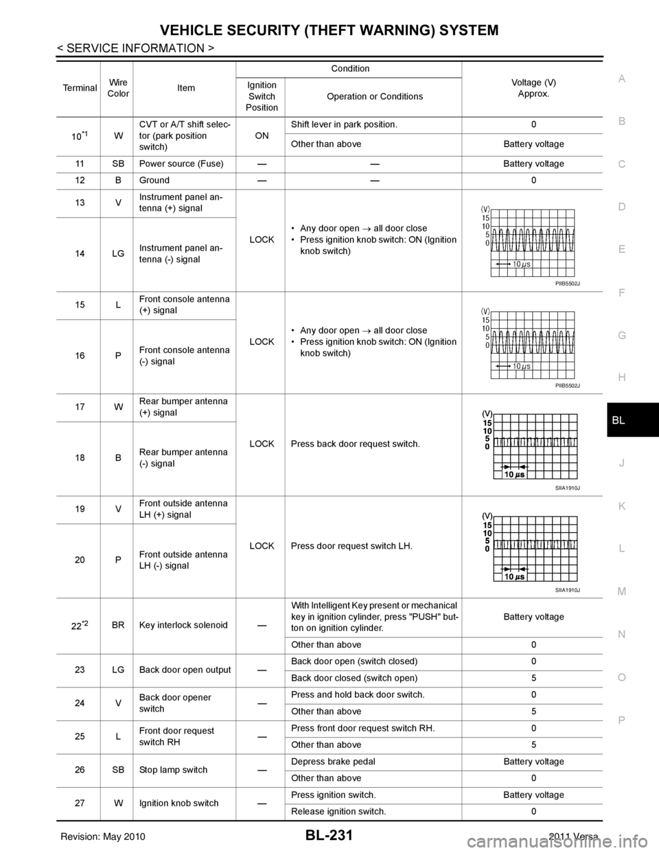
10*1W CVT or A/T shift selec-
tor (park position
switch)
ONShift lever in park position.
0
Other than above Battery voltage
11 SB Power source (Fus e) — —Battery voltage
12 B Ground —— 0
13 V Instrument panel an-
tenna (+) signal
LOCK• Any door open
→ all door close
• Press ignition knob switch: ON (Ignition knob switch)
14 LG Instrument panel an-
tenna (-) signal
15 L Front console antenna
(+) signal
LOCK• Any door open
→ all door close
• Press ignition knob switch: ON (Ignition knob switch)
16 P Front console antenna
(-) signal
17 W Rear bumper antenna
(+) signal
LOCK Press back door request switch.
18 B Rear bumper antenna
(-) signal
19 V Front outside antenna
LH (+) signal
LOCK Press door request switch LH.
20 P Front outside antenna
LH (-) signal
22
*2BR Key interlock solenoid — With Intelligent Key present or mechanical
key in ignition cylinder, press "PUSH" but-
ton on ignition cylinder.
Battery voltage
Other than above 0
23 LG Back door open output — Back door open (switch closed)
0
Back door closed (switch open) 5
24 V Back door opener
switch —Press and hold back door switch.
0
Other than above 5
25 L Front door request
switch RH
—Press front door request switch RH.
0
Other than above 5
26 SB Stop lamp switch —Depress brake pedal
Battery voltage
Other than above 0
27 W Ignition knob switch — Press ignition switch.
Battery voltage
Release ignition switch. 0
Terminal
Wire
Color Item Condition
Voltage (V)Approx.
Ignition
Switch
Position Operation or Conditions
PIIB5502J
PIIB5502J
SIIA1910J
SIIA1910J
Revision: May 2010
2011 Versa
Page 848 of 3787

BR-1
BRAKES
C
DE
G H
I
J
K L
M
SECTION BR
A
B
BR
N
O P
CONTENTS
BRAKE SYSTEM
SERVICE INFORMATION .. ..........................2
PRECAUTIONS .............................................. .....2
Precaution for Supplemental Restraint System
(SRS) "AIR BAG" and "SEAT BELT PRE-TEN-
SIONER" ............................................................. ......
2
Precaution Necessary for Steering Wheel Rota-
tion After Battery Disconnect ............................... ......
2
Precaution for Brake System ....................................3
PREPARATION ...................................................4
Special Service Tool ........................................... ......4
Commercial Service Tool ..........................................4
NOISE, VIBRATION AND HARSHNESS
(NVH) TROUBLESHOOTING .............................
5
NVH Troubleshooting Chart ................................ ......5
BRAKE PEDAL .............................................. .....6
Inspection and Adjustment .................................. ......6
Removal and Installation ...........................................7
BRAKE FLUID ................................................ .....9
On Board Inspection ........................................... ......9
Drain and Refill ..........................................................9
Bleeding Brake System .............................................9
BRAKE TUBE AND HOSE ................................11
Hydraulic Circuit .................................................. ....11
Front Brake Tube and Hose ....................................12
Rear Brake Tube and Hose ....................................12
Inspection After Installation .....................................13
DUAL PROPORTIONING VALVE .....................14
Removal and Installation .........................................14
Inspection ............................................................ ....14
BRAKE MASTER CYLINDER ........................ ....15
On-Board Inspection ........................................... ....15
Removal and Installation ..................................... ....15
Disassembly and Assembly .....................................16
BRAKE BOOSTER ...........................................20
On Board Inspection ............................................ ....20
Removal and Installation .........................................21
VACUUM LINES ...............................................23
Component ..............................................................23
Removal and Installation .........................................23
Inspection ................................................................23
FRONT DISC BRAKE .......................................25
On Board Inspection ............................................ ....25
Component ..............................................................25
Removal and Installation of Brake Pad ...................26
Removal and Installation of Brake Caliper Assem-
bly ........................................................................ ....
30
Disassembly and Assembly of Brake Caliper As-
sembly .....................................................................
31
Brake Burnishing Procedure ....................................34
REAR DRUM BRAKE .......................................35
Component .......................................................... ....35
Removal and Installation of Drum Brake Assembly
....
36
Removal and Installation of Wheel Cylinder ............39
Disassembly and Assembly of Wheel Cylinder .......39
SERVICE DATA AND SPECIFICATIONS
(SDS) .................................................................
40
General Specification ..............................................40
Brake Pedal .............................................................41
Check Valve ............................................................41
Brake Booster ..........................................................42
Front Disc Brake ......................................................42
Rear Drum Brake .....................................................42
Revision: May 2010 2011 Versa
Page 850 of 3787
PRECAUTIONSBR-3
< SERVICE INFORMATION >
C
DE
G H
I
J
K L
M A
B
BR
N
O P
5. When the repair work is completed, return the ignition switch to the ″LOCK ″ position before connecting
the battery cables. (At this time, the steering lock mechanism will engage.)
6. Perform a self-diagnosis check of al l control units using CONSULT-III.
Precaution for Brake SystemINFOID:0000000005928387
• Refill using recommended brake fluid. Refer to MA-14.
• Never reuse drained brake fluid.
• Be careful not to splash brake fluid on painted surface of body. If brake fluid is splashed on painted surfaces of body immediately wipe it off with cloth and then wash it away with water.
• To clean or wash all parts of master cylinder, disc brake caliper and wheel cylinder, use new brake fluid.
• Never use mineral oils such as gasoline or kerosene. They will ruin rubber parts of the hydraulic system.
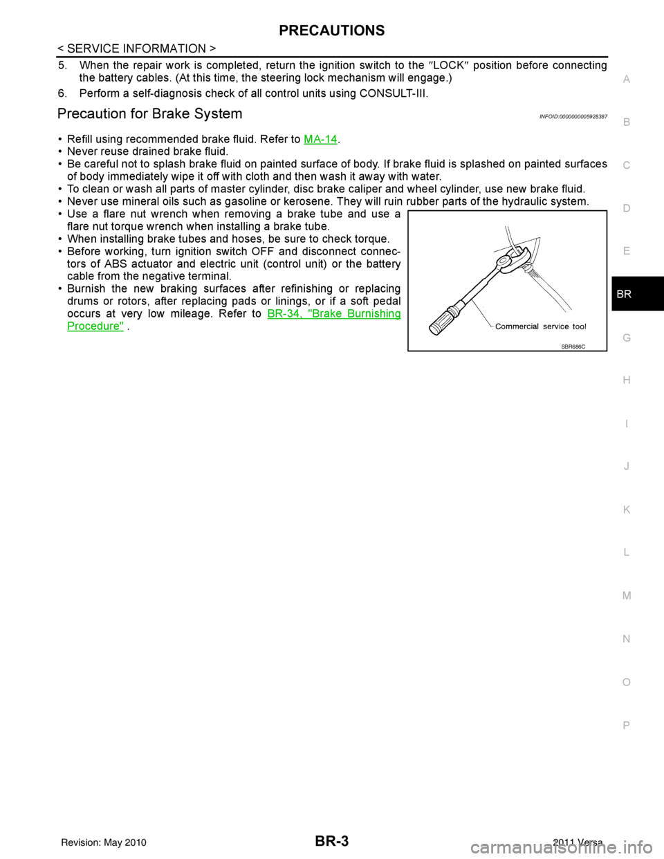
• Use a flare nut wrench when removing a brake tube and use a flare nut torque wrench when installing a brake tube.
• When installing brake tubes and hoses, be sure to check torque.
• Before working, turn igniti on switch OFF and disconnect connec-
tors of ABS actuator and electric unit (control unit) or the battery
cable from the negative terminal.
• Burnish the new braking surfaces after refinishing or replacing drums or rotors, after replacing p ads or linings, or if a soft pedal
occurs at very low mileage. Refer to BR-34, "
Brake Burnishing
Procedure" .
SBR686C
Revision: May 2010 2011 Versa