Page 157 of 602
3-60 Features and controls
3Steering wheel height and reach adjustment
N00511500228
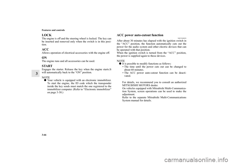
To adjust the steering wheel to the desired position, move the
lever upward or downward while moving the steering wheel to
the desired level.
CAUTION
!�Before driving, be sure that the parking brake is
fully released and brake warning light is off.
If you drive without the parking brake fully
released, the warning display will appear on the
information screen in the multi-information display.
If a vehicle is driven without releasing the parking
brake, the brakes will be overheated, resulting in
ineffective braking and possible brake failure.
Warning light
Warning display type 1
Warning display type 2
A- Wheel lock
B- Release
BK0120400US.book 60 ページ 2010年5月12日 水曜日 午前10時50分
Page 158 of 602
Features and controls
3-61
3 Inside rearview mirror
N00511600245
Adjust the inside rearview mirror only after making any seat
adjustments so as to have a clear view to the rear of the vehicle.
WA R N I N G
!�After adjusting, make sure the lever is secured in the
locked (A) position.�Do not attempt to adjust the steering wheel while
driving. This can be dangerous.�When releasing the lever (moving it to the position
(B)), be sure to hold the steering wheel firmly. Oth-
erwise, the steering wheel may slip down too sud-
denly.
WA R N I N G
!�Do not attempt to adjust the inside rearview mirror
while driving. This can be dangerous.
Be sure to adjust the mirrors before driving.
BK0120400US.book 61 ページ 2010年5月12日 水曜日 午前10時50分
Page 163 of 602

3-66 Features and controls
3
LOCKThe engine is off and the steering wheel is locked. The key can
be inserted and removed only when the switch is in this posi-
tion.ACCAllows operation of electrical accessories with the engine off.ONThe engine runs and all accessories can be used.STARTEngages the starter. Release the key when the engine starts.It
will automatically back to the “ON” position.NOTE�Your vehicle is equipped with an electronic immobilizer.
To start the engine, the ID code which the transponder
inside the key sends must match the one registered to the
immobilizer computer. (Refer to “Electronic immobilizer”
on page 3-30.)
ACC power auto-cutout function
N00539600058
After about 30 minutes has elapsed with the ignition switch in
the “ACC” position, the function automatically cuts out the
power for the audio system and other electric devices that can
be operated with that position.
When the ignition switch is turned from the “ACC” position,
the power is supplied again to those devices.NOTE�It is possible to modify functions as follows:
• The time until the power cuts out can be changed to
about 60 minutes.
• The ACC power auto-cutout function can be deacti-
vated.
For details, we recommend you to consult an authorized
MITSUBISHI MOTORS dealer.
On vehicles equipped with Mitsubishi Multi-Communica-
tion System, screen operations can be used to make the
adjustment.
Refer to the separate Mitsubishi Multi-Communications
System manual for details.
BK0120400US.book 66 ページ 2010年5月12日 水曜日 午前10時50分
Page 164 of 602
Features and controls
3-67
3
To remove the key
N00550900171
1. Set the selector lever to the “P” (PARK) position {contin-
uously variable transmission (CVT)}.
2. Push the key in at the “ACC” position and keep it
depressed until it is turned to the “LOCK” position and
remove it.
CAUTION
!�Do not remove the ignition key from the ignition
switch while driving. The steering wheel will be
locked, causing loss of control.�If the engine is stopped while driving, the brake ser-
vomechanism will cease to function and braking
efficiency will deteriorate. Also, the power steering
system will not function and it will require greater
manual effort to operate the steering.�Do not leave the key in the “ON” position for a long
time when the engine is not running, doing so will
cause the battery to be discharged.�Do not turn the key to the “START” position when
the engine is running, doing so could damage the
starter motor.
BK0120400US.book 67 ページ 2010年5月12日 水曜日 午前10時50分
Page 165 of 602
3-68 Features and controls
3Steering wheel lock
N00512500182
[For vehicles equipped with the Free-hand Advanced Secu-
rity Transmitter (F.A.S.T.-key)]
For information on operations for vehicles equipped with the
Free-hand Advanced Security Transmitter (F.A.S.T.-key), refer
to “Free-hand Advanced Security Transmitter (F.A.S.T.-key):
Steering wheel lock” on page3-25
[Except for vehicles equipped with the Free-hand
Advanced Security Transmitter (F.A.S.T.-key)]
To l o c kRemove the key at the “LOCK” position.
Turn the steering wheel until it is locked.To u n l o c kTurn the key to the “ACC” position while moving the steering
wheel slightly.NOTE�If the front wheels are turned, the anti-theft lock may
sometimes make it difficult to turn the key from “LOCK”
to “ACC”. Firmly turn the steering wheel to the left or to
the right as you turn the key.
CAUTION
!�Remove the key when leaving the vehicle.
BK0120400US.book 68 ページ 2010年5月12日 水曜日 午前10時50分
Page 166 of 602
![MITSUBISHI OUTLANDER SPORT 2011 3.G Owners Manual Features and controls
3-69
3 Starting the engine
N00512600688
[For vehicles equipped with the Free-hand Advanced Secu-
rity Transmitter (F.A.S.T.-key)]
For information on operations for vehicles equip MITSUBISHI OUTLANDER SPORT 2011 3.G Owners Manual Features and controls
3-69
3 Starting the engine
N00512600688
[For vehicles equipped with the Free-hand Advanced Secu-
rity Transmitter (F.A.S.T.-key)]
For information on operations for vehicles equip](/manual-img/19/7539/w960_7539-165.png)
Features and controls
3-69
3 Starting the engine
N00512600688
[For vehicles equipped with the Free-hand Advanced Secu-
rity Transmitter (F.A.S.T.-key)]
For information on operations for vehicles equipped with the
Free-hand Advanced Security Transmitter (F.A.S.T.-key), refer
to “Free-hand Advanced Security Transmitter (F.A.S.T.-key):
Starting” on page3-14.
[Except for vehicles equipped with the Free-hand
Advanced Security Transmitter (F.A.S.T.-key)]Tips for starting�Do not operate the starter motor continuously for longer
than 15 seconds as this could run the battery down or
damage the starter motor. If the engine does not start, turn
the ignition switch back to the “LOCK” position, wait a
few seconds, and then try again. Trying repeatedly with
the engine or starter motor still turning will damage the
starter mechanism.
�If the engine will not start because the battery is weak or
discharged, refer to “Jump-starting the engine” (on page
6-2) for instructions.
�A longer warm up period will only consume extra fuel.
The engine is warmed up enough for driving when the bar
graph of engine coolant temperature display starts to
move. Refer to “Interrupt display screen (When the igni-
tion switch is in the “ON” position)” on page 3-140.
Starting the engineThis model is equipped with an electronically controlled fuel
injection system. This is a system that automatically controls
fuel injection. There is no need to depress the accelerator pedal
when starting the engine.
The starter should not be run for more than 15 seconds at a
time.
To prevent battery drain, wait a few seconds between attempts
to restart the engine.
1. Make sure all occupants are properly seated with seat
belts fastened.
2. Insert the ignition key.
WA R N I N G
!�Never run the engine in a closed or poorly ventilated
area any longer than is needed to move your vehicle
out of the area. Carbon monoxide gas, which is
odorless and extremely poisonous, could build up
and cause serious injury or death.
CAUTION
!�Do not push-start the vehicle.�Do not run the engine at high rpms or drive at high
speeds until the engine has had a chance to warm
up.�Release the ignition switch as soon as the engine
starts. Otherwise, the starter motor will be dam-
aged.
BK0120400US.book 69 ページ 2010年5月12日 水曜日 午前10時50分
Page 167 of 602

3-70 Features and controls
3
3. Make sure the parking brake is applied.
4. Press and hold the brake pedal down with your right foot.
5. Press and hold the clutch pedal all the way down (manual
transaxle).
6. On vehicles equipped with manual transaxle, place the
gearshift lever in the “N” (Neutral) position.
On vehicles equipped with continuously variable trans-
mission (CVT), make sure the selector lever is in the “P”
(PARK) position.NOTE�On vehicles equipped with CVT, the starter will not oper-
ate unless the selector lever is in the “P” (PARK) or “N”
(NEUTRAL) position.
For safety reasons, start the engine in the “P” (PARK)
position so that the wheels are locked.
7. Turn the ignition switch to the “ON” position and make
certain that all warning lights are functioning properly
before starting the engine.
8. Turn the ignition switch to the “START” position without
pressing the accelerator pedal. Release the key when the
engine starts.NOTE�Minor noises may be heard on engine start-up. These will
disappear as the engine warms up.
Startability of automatic transaxle vehicle and CVT
vehicle with ambient temperature of -22
°F (-30
°C) or
lower
When the ambient temperature is -22 °F (-30 °C) or lower, it
may not be possible to start from a standstill even with the
selector lever in the “D” (DRIVE) position.
This occurs because the transaxle has not warmed up suffi-
ciently; it does not indicate a problem. If this occurs, place the
selector lever in the “P” (PARK) position and let the engine
idle for at least 10 minutes.
The transaxle will warm up, and you will be able to start nor-
mally.
Do not leave the vehicle during warm-up operation.
BK0120400US.book 70 ページ 2010年5月12日 水曜日 午前10時50分
Page 171 of 602

3-74 Features and controls
3
Selector lever operation
N00560300035
As an additional safety precaution, models equipped with a
continuously variable transmission have a shift-lock device
that holds the selector lever in the “P” (PARK) position. To
move the selector lever from the “P” (PARK) position to
another position, follow the steps below.
1. Press and hold the brake pedal down.
2. Move the selector lever to the desired position.NOTE�The selector lever cannot be moved from “P” (PARK) to
another position if the ignition switch is set to the
“LOCK” or “ACC” position, or if the key has been
removed, or if the brake pedal is not pressed and held
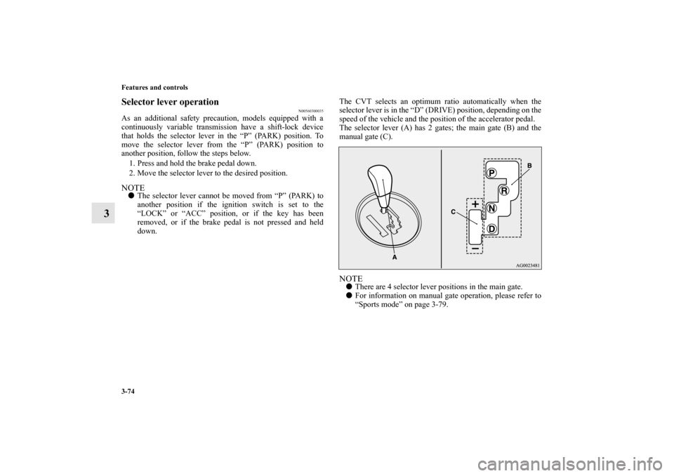
down.The CVT selects an optimum ratio automatically when the
selector lever is in the “D” (DRIVE) position, depending on the
speed of the vehicle and the position of the accelerator pedal.
The selector lever (A) has 2 gates; the main gate (B) and the
manual gate (C).
NOTE�There are 4 selector lever positions in the main gate.
�For information on manual gate operation, please refer to
“Sports mode” on page 3-79.
BK0120400US.book 74 ページ 2010年5月12日 水曜日 午前10時50分