2011 MERCEDES-BENZ E-CLASS CABRIOLET service
[x] Cancel search: servicePage 200 of 353

Example: Coupé
G
WARNING
Blind Spo tAssist monitors certain areas in the
immediate vicinity of your vehicle. Vehicles
that approach and drive past at high speeds
are not detected. There is no displaya nd no
warning.
If the lanes are very wide, it may not be pos-
sible to monitor the complete width of the
neighbouring lane. For this reason, vehicles in
the next lane may not be detected, especially
if they are driving in astaggered formation in
different lanes. This may be the case if vehi-
cles are driving at the edge of their lane that
is furthest awayf rom your vehicle.
Always pay attention to traffic conditions and
your surroundings. Otherwise, you may fail to
recognise dangers in time, cause an accident
and injure yourselfa nd others.
If the lanes ar enarrow ,the system may be
unable to distinguish the neighbouring lane
from the one beyond it. For this reason, vehi-
cles in the farther lane may be indicated,
especiallyift he vehicles are driving in astag-
gered formation in different lanes. In particu-
lar, this may be the case if the vehicles are
driving at the edge of their lane nearest your
vehicle. Due to the nature of the system:
R
warnings may be issued in error when driv-
ing close to crash barriers or similar solid
lane borders.
R warnings may be interrupted when driving
alongside particularly long vehicles, for
example lorries, for aprolonged time.
The two sensors for Blind Spot Assist are
integrated into the sides of the rear bumper.
Make sure that the bumper is free of dirt, ice
or slush around the sensors. For example, the
radar sensors must not be covered by cycle
racks or overhanging loads. Following a
severe impact or in the event of damage to
the bumpers, have the function of the radar
sensors checked at aqualified specialist
workshop, e.g. aMercedes-Ben zService
Centre. Blind Spot Assist may otherwise not
work properly.
Indicator and warning display :
Yellow indicator lamp/red warning lamp
If Blind Spot Assist is switched on, indicator
lamp :in the exterior mirror slights up yel-
low up to aspeed of 30 km/h. At speeds
above 30 km/h, the indicator lamp goes out
and Blind Spot Assist is operational.
If av ehicle is detected within the monitoring
range of Blind Spot Assist at speeds above
30 km/h, warning lamp :on the corre-
spondin gside lights up in red. This warning is
alway semitted when avehicle enters the
blind spot monitoring range from behind or
from the side. When you overtake avehicle, Driving systems
197Driving and parking Z
Page 203 of 353

Monitoring range
Active Blind Spot Assist monitors the area up
to three metres behind yourv
ehicle and
directly nexttoy our vehicle, as shown in the
diagram. For this purpose, Active Blind Spot
Assist uses radar sensors in the rear bumper. Example: Coupé
G
WARNING
Active Blind Spot Assist monitors certain
areas in the immediate vicinit yofyour vehicle.
Vehicles that approach and drive past at high
speeds are not detected. No visual nor audi-
ble warnings are emitted and the system does
not brake the vehicle to correc tyour course.
If the lanes are very wide, it may not be pos-
sible to monitor the complete width of the
neighbouring lane. For this reason, vehicles in
the next lane may not be detected, especially
if they are driving in astaggered formation.
This may be the case if vehicles are driving at
the edge of their lane that is furthest away
from your vehicle.
Always pay attention to traffic conditions and
your surroundings. Otherwise, you may fail to
recognise dangers in time, cause an accident
and injure yourself and others.
If the lanes are narrow, vehicles driving in the
lane beyond the lane next to your vehicle may
be indicated, especially if the vehicles are not driving in the middle of their lane. This may
be the case if the vehicles are driving on the
inner side of their lane.
Due to the nature of the system:
R
warnings may be issued in error when driv-
ing close to crash barriers or similar solid
lane borders.
R warnings may be interrupted when driving
alongside particularly long vehicles, for
example lorries, for aprolonged time.
Two Active Blind Spot Assist radar sensors
are integrated into the front and rear bumpers
respectively. An additional radar sensor is
located behind the cover in the radiator grille.
Make sure that the bumpers are free of dirt,
ice or slush around the sensors. The rear sen-
sors must not be covered, for example by
cycle racks or overhanging loads. Following a
severe impact or in the event of damage to
the bumpers, have the function of the radar
sensors checked at aqualified specialist
workshop, e.g. aMercedes-Benz Service
Centre. Active Blind Spot Assist may other-
wise fail to work correctly.
Indicator and warning display :
Yellow indicator lamp/red warning lamp
When Active Blind Spot Assist is activated,
indicator lamp :in the exterior mirrors lights
up in yellow at speeds of up to 30 km/h. At
speeds above 30 km/h, the indicator lamp
goes out and Active Blind Spot Assist is
operational.
If av ehicle is detected within the monitoring
range of Blind Spot Assist at speeds above 200
Driving systemsDriving and parking
Page 212 of 353

You can obtain further information about
installing the trailer electrics fro maqualified
specialist workshop, e.g. aMercedes-Benz
Service Centre.
X To switch the connected power supply
on or off: turn the key in the ignition lock
to position 2or 0respectively. Bulb failur
eindicator for LED lamps
i If LED lamps are fitted in the trailer, an
error message may appear in the multi-
function display even if ther eisnofault. The
reason for the error message may be that
the curren thas falle nbelow the minimum
of 50 milliamperes (mA).
To ensure reliable operation of the bulb failure
indicator, each LED chain in the trailer lighting
must be guaranteed aminimum curren tof
50 mA. Trailer with 7-pin connector
General information If your trailer has
a7-pin connector, you can
connectittot he 13-pin socket on the ball
coupling using an adapter or, if necessary, an
adapter cable. Bothoft hese can be obtained
at aq ualified specialist workshop, e.g. at a
Mercedes-Benz Service Centre.
Fitting the adapter X
Open the socket cover.
X Inser tthe connector with lug :into
groove ;on the socket and turn the con-
nector clockwise to the stop.
X Let the cover engage.
X If you are using an adapter cable, secure
the cable to the trailer with cable ties.
! Make sure that ther eissufficien tcable
play so that th ecabl ecanno tbecome
detached when cornering. Trailer towing
209Driving and parking Z
Page 215 of 353

Useful information
i This Owner's Manual describes all models
and all standard and optional equipment
available to your vehicle at the time of pub-
lication of the Owner's Manual. Country-
specific deviation sare possible. Please
not ethat your vehicle may not be equipped
with all feature sdescribed. This also
applies to safety-relevan tsystems and
functions.
i Pleas ereadt he information on qualified
specialist workshop s(Ypage 22). Important safet
ynotes
You will fin danillustration of th einstrument
cluster in th e"At ag lance "section
(Y page 28). G
WARNING
Only use th eon-bo ardc om puter when road
and traffic condition spermit .You would oth-
erwise be distracted and unable to concen-
trate properly on driving, and could cause an
accident. G
WARNING
If the instrument cluster or multifunction dis-
play fails, no messages can be displayed.
This means that you will not see information
about the driving situation, such as the speed,
outside temperature, warning/indicator
lamps, display messages or system failures.
Handling characteristics may be affected.
Adapt your driving style and speed accord-
ingly.
Immediately consult aqualified specialist
workshop which has the necessary specialist
knowledge and tools to carry out the work
required. Mercedes-Benz recommends that
you use aMercedes-Benz Service Centre for
this purpose. In particular, work relevant to
safety or on safety-related systems must be
carried out at aqualified specialist workshop. G
WARNING
The on-board computer only records and dis-
plays malfunctions and warnings from certain
systems. For this reason, you should always
make sure that your vehicle is safe to use. You
could otherwise cause an accident by driving
an unsafe vehicle. G
WARNING
The operating safety of your vehicle could be
jeopardised if maintenance work is carried
out incorrectly. As aresult, you could lose
control of the vehicle and cause an accident.
In addition, the safety systems may no longer
be able to protec tyou or others as they are
designed to do.
Always have maintenance work carried out at
aq ualified specialist workshop. The qualified
specialist workshop must have the necessary
specialist knowledge and tools to carry out
the work required. Mercedes-Benz recom-
mends that you use aMercedes-Benz Service
Centre for this purpose. In particular, work
relevant to safety or on safety-related sys-
tems must be carried out at aqualified spe-
cialist workshop. Displays and operation
Coolant temperature gauge
The coolant temperature gauge is in the
instrument cluster on the right-hand side.
Under normal operating conditions and with
the specified coolant level, the coolant tem-
perature may rise to 120 †.
At high outside temperatures and when driv-
ing uphill, the coolant temperature may rise
to the end of the scale. Rev counter
The red band in the rev counter indicates the
engine's overrevving range. 212
Displays and operationOn-board computer and displays
Page 219 of 353

Menus and submenus
Menu overview
The number of menus show ndepends on the optional equipment in the vehicle. Function
:
Trip menu (Y
page 217) ;
Navi menu (navigation instructions) (Y
page 218)=
Audio menu (Y
page 219) ?
Tel menu (telephone) (Y
page 221)A
Assist. menu (assistance) (Y
page 222)B
Service menu (Y
page 224)
R calls up display messages ( Ypage 232)
R tyre pressure loss warning (Y page 322)
R ASSYST PLUS servic einterval display (Y page 284) C
Settings menu (Y
page 224) The
Audio ,
Navi and
Tel menus differ slightly in vehicles with an audio system and vehicles
with COMAND APS.T he examples given in this Owner's Manual apply to vehicles equipped
with COMAND APS. 216
Menus and submenusOn-board computer and displays
Page 224 of 353

Telephon
emenu
Introduction Functions and displays ar
edependen tonthe
optional equipment installed in your vehicle.
You can place your mobile phone in the
mobile phone bracket (Y page 273), or set
up aB luetooth ®
connection to the audios ys-
tem or COMAND APS (see the separate oper-
ating instructions).
i You can obtain further information about
suitable mobile phones and connecting
mobile phones via Bluetooth ®
:
R in any Mercedes Benz Service Centre
R on the Internet at http://
www.mercedes-benz.com/connect G
WARNING
Observe the legal requirements of the country
in which you are currently driving regarding
the use of mobile phones in the vehicle.
If it is permitted to use mobile phones while
the vehicle is in motion, you should only use
them when the road and traffic conditions
allow.O therwise, yo umaybe distracted from
the traffi cconditions ,cause an accident and
injure yourself and others.
X Switch on the mobil ephone and audi osys-
tem or COMAND APS (see the separate
operating instructions).
X Press the =or; button on the steer-
ing whee ltoselect theTel menu.
Yo uw ills ee one of the following displa ymes-
sage sint he multifunctio ndisplay:
R Please enter PIN :t
he mobile phone has
been placed in the mobile phone bracket
and the PIN has not been entered.
X Enter the PIN using the mobile phone, LIN-
GUATRONIC, the audios ystem or
COMAND APS.
The mobile phone will search for anetwork. R
Telephone ready or the name of the net-
work provider: the mobile phone has found
an etwork and is ready to receive.
R Telephone No Service :non
etwork is
available, or the mobile phone is searching
for anetwork.
Accepting acall If someone call
syou whe nyou are in the
Tel menu,
adisplay message appears in the
multifunction display ,for example: X
Press the 6button on the steering
wheel to accept an incomin gcall.
If you are not in the Tel menu, you can still
accept acall.
Rejecting or ending acall X
Press the ~button on the steering
wheel.
If you are not in the Tel menu, you can still
reject or end acall.
Dialling anumber from the phone book If you
rmobile phone is able to receive calls,
you can search for and dial anumber from the
phone book in the audio system or COMAND
APS at any time.
X Copy the telephone book of the mobile
phone into the audio system or to COMAND
APS (see the separate operating instruc-
tions).
X Press the =or; button on the steer-
ing wheel to select the Tel menu.
X Press the 9,:ora button to call
up the phone book. Menus and submenus
221On-board computer and displays Z
Page 227 of 353

Vehicles with Parking Guidance:
if PARK-
TRONIC is activate dand yo uare driving at a
spee dunder 35 km/h, the jParking Guid-
ance symbol is show ninstea doftheÄ
symbol.
Activating/deactivating Attention
Assist X
Press =or; on the steering wheel
to select the Assist. menu.
X Press the 9or: button to select
Attention Asst. .
X Press a.
The current selection is displayed.
X To activate/deactivate: pressa
again.
When ATTENTION ASSIST (Y page 194) is
activated, the Àsymbol appears in the
multifunction displayw hen the ignition is on.
Activating/deactivating Blind Spot
Assist You can use the
Blind Spot Asst. function
to activate or deactivate Blind Spot Assist
(Y page 196) or Active Blind Spot Assist
(Y page 199).
X Press =or; on the steering wheel
to select the Assist. menu.
X Press 9or: to select Blind Spot
Asst. .
X Press a.
If the function is activated, the monitored
areas in the multifunction displayl ight up
red.
X To activate/deactivate: pressa
again.
Activating/deactivating Lane Keeping
Assist You can use the
Lane Keep. Asst. function
to activate/deactivate Lane Keeping Assist
(Y page 198) or Active Lane Keeping Assist
(Y page 202). X
Press =or; on the steering wheel
to select the Assist. menu.
X Press 9or: to select Lane Keep.
Asst. .
X Press a.
If the function is activated, the lane marking
symbol in the multifunction displayl ights
up red.
X To activate/deactivate: pressa
again.
When Lane Keeping Assist or Active Lane
Keeping Assist is activated, the Ãsymbol
appears in the multifunction displayw hen the
ignition is on. Service menu
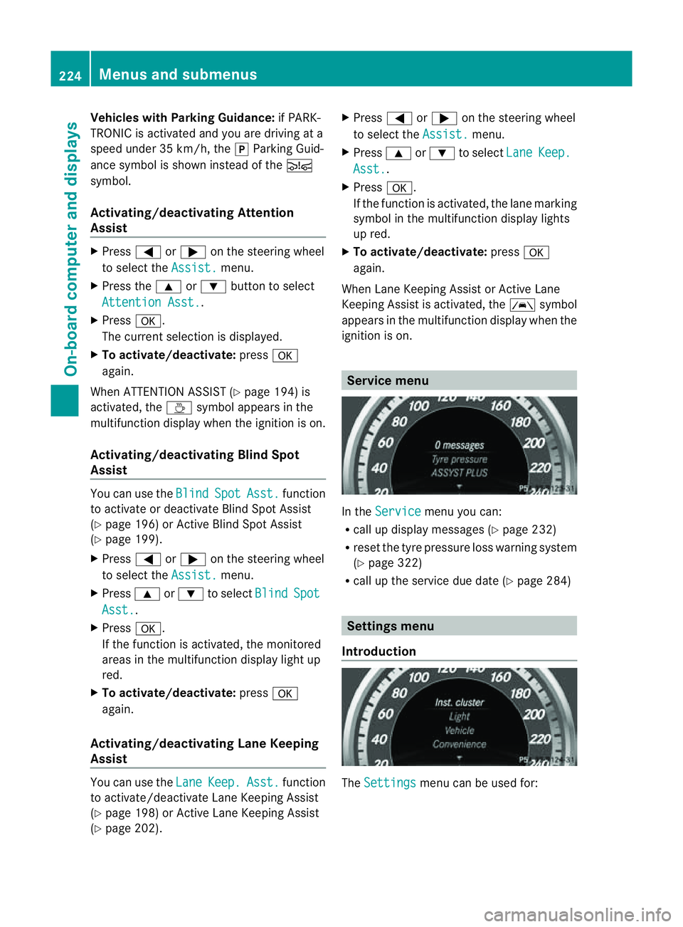
In the
Service menu you can:
R call up displaym essages (Ypage 232)
R reset the tyre pressure loss warning system
(Y page 322)
R call up the service due date (Y page 284) Settings menu
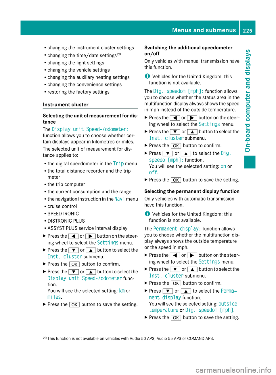
Introduction The
Settings menu can be used for:224
Menus and submenusOn-board computer and displays
Page 228 of 353

R
changing the instrument cluster settings
R changing the time/date settings 20
R changing the light settings
R changing the vehicle settings
R changing the auxiliary heating settings
R changing the convenience settings
R restoring the factory settings
Instrumen tcluster Selecting th
eunit of measurement for dis-
tance
The Display unit Speed-/odometer: function allows you to choose whether cer-
tain displays appear in kilometres or miles.
The selected unit of measurement for dis-
tance applies to:
R the digital speedometer in the Trip menu
R the total distanc erecorder and the trip
meter
R the trip computer
R the current consumption and the range
R the navigation instruction in the Navi menu
R cruis econtrol
R SPEEDTRONIC
R DISTRONIC PLUS
R ASSYS TPLUS service interval display
X Press the =or; button on the steer-
ing wheel to selec tthe Settings menu.
X Press the :or9 button to select the
Inst. cluster submenu.
X Press the abutton to confirm.
X Press the :or9 button to select the
Display unit Speed-/odometer func-
tion.
You will see the selected setting: km or
miles .
X Press the abutton to save the setting. Switching the additional speedometer
on/off
Only vehicles with manual transmission have
this function.
i
Vehicles for the United Kingdom: this
function is not available.
The Dig. speedom [mph]: function allows
you to choose whether the status area in the
multifunction displaya lways shows the speed
in mph instead of the outside temperature.
X Press the =or; button on the steer-
ing wheel to select the Settings menu.
X Press the :or9 button to select the
Inst. cluster submenu.
X Press the abutton to confirm.
X Press :or9 to select the Dig. speedo [mph]: function.
You will see the selected setting: on or
off .
X Press the abutton to save the setting.
Selecting the permanent display function
Only vehicles with automatic transmission
have this function.
i Vehicles for the United Kingdom: this
function is not available.
The Permanent display: function allows
you to choose whether the multifunction dis-
play always shows the outside temperature
or the speed in mph.
X Press the =or; button on the steer-
ing wheel to select the Settings menu.
X Press the :or9 button to select the
Inst. cluster submenu.
X Press the abutton to confirm.
X Press :or9 to select the Perma‐ nent display function.
You will see the selected setting: outside temperature or
Dig. speedom [mph] .
X Press the abutton to save the setting.
20 This function is not available on vehicles with Audio 50 APS, Audio 55 APS or COMAND APS. Menus and submenus
225On-board computer and displays Z