2011 MERCEDES-BENZ C-CLASS COUPE key
[x] Cancel search: keyPage 297 of 373

Garage door opener
Important safety notes The HomeLink
®
garage door opener integra-
ted in the rear-view mirror allows you to oper-
ate up to three different door and gate sys-
tems.
i The garage door opener is only available
for certain countries. Observe the legal
requirements in each country.
The HomeLink ®
garage door opener is
compatible with most Europea ngarage and
gate opener drives. More informatio non
HomeLink ®
and/o rcompatible products is
available from:
R any Mercedes-Benz Service Centre
R the HomeLink ®
hotline
(0) 08000 466 354 65 (free of charge) or
+49 (0) 6838 907 277 (charges apply)
R on the Internet at:
http://www.homelink.com
Programming the integrated garage
door opener in the rear-view mirror Programming
G
WARNING
Only press the transmitter button on the inte-
grated garage door opener if there are no per-
sons or objects present within the sweep of
the garage door. Persons could otherwise be
injured as the door moves. Integrated garage door opener in the rear-view mir-
ror Garage door remote control
Ais not part of
this integrated garage door opener.
i To achieve the best results, insert new
batteries in garage door remote control
A before programming.
X Before programming for the first time, clear
the memory of the integrated garage door
opener (Y page 296).
X Turn the key to position 2in the ignition
lock.
X Press and hold one of transmitter but-
tons ;to? on the integrated garage door
opener.
After a short time, indicator lamp :starts
flashing yellow.
i Indicator lamp :flashes yellow immedi-
ately the first time that the transmitter but-
ton is programmed. If this transmitter but-
ton has already been programmed, indica-
tor lamp :only starts flashing yellow after
10 seconds have elapsed.
X Release the transmitter button.
X Point transmitter button Bof garage door
remote control Atowards the transmitter
buttons on the rear-view mirror at a dis-
tance of 5 to 20 cm.
i The required distance between garage
door remote control Aand the integrated
door opener depends on the garage door
drive system. You might require several
attempts. You should test every position for
at least 25 seconds before trying another
position.
X Press and hold transmitter button Bon
garage door remote control Auntil indi-
cator lamp :lights up green.
The programming has been successful if
indicator lamp :lights up or flashes
green.
X Release transmitter button ;,=or? on
the integrated garage door opener and the
transmitter button on garage door remote
control B. 294
FeaturesStowing and features
Page 298 of 373

If indicator lamp
:lights up red:
X Repeat the programming procedure for the
transmitter buttons. When doing so, vary
the distance betwee nthe garage door drive
remote control and the rear-view mirror.
i If the indicator lamp flashes green after
successful programming, the garage door
system is using a rolling code. After pro-
gramming, you must synchronise the
garage door opener integrated in the rear-
view mirror with the receiver of the garage
door system.
Synchronising the rolling code
Your vehicle must be within reach of the
garage or gate opener drive. Make sure that
neither your vehicle nor any persons/objects
are present within the sweep of the door or
gate.
Observe the safety notes when performing
the rolling code synchronisation.
X Turn the key to position 2in the ignition
lock.
X Press the programming button of the door
or gate drive (see the door or gate drive
operating instructions, e.g. under "Pro-
gramming of additional remote controls").
i Usually, you now have 30 seconds to ini-
tiate the next step.
X Press the previously programmed button of
the integrated HomeLink ®
garage door
opener repeatedly until the door starts to
move.
The rolling code synchronisation is then
complete.
Problems when programming
If you have problems when programming the
integrated garage door opener, please note
the following:
R check the transmitter frequency of garage
door remote control A(this can usually be
found on the rear of the remote control).
R change the batteries in garage door remote
control A.This increases the likelihood that garage door remote control
Awill
send a strong and precise signal to the
integrated remote control in the rear-view
mirror.
R when programming, hold garage door
remote control Aat different distances
and angles from the transmitter button that
you are programming. Try various angles at
a distance of between 5 and 30 cm or the
same angle but varying distances.
R if there is another remote control for the
same garage door drive, perform the pro-
gramming steps again using this remote
control. Before performing these steps,
make sure that new batteries have been
fitted in the garage door drive remote con-
trol.
R note that some remote controls transmit
only for a limited period (the indicator lamp
on the remote control goes out). Press the
button on the remote control again before
transmission ends.
R align the aerial cable of the garage door
opener unit. This can improve signal recep-
tion/transmission.
Opening or closing the garage door Once programmed, the integrated garage
door opener will assume the function of the
garage door system's remote control. Please
also read the operating instructions for the
garage door system.
X
Turn the key to position 2in the ignition
lock.
X Press overhead control panel transmitter
button ;,=or? that you have pro-
grammed to operate the garage door.
Garage door system with a fixed code: indi-
cator lamp :lights up green.
Garage door system with a rolling code:
indicator lamp :flashes green.
i The transmitter will transmit a signal for
as long as the transmitter button is
pressed. The transmission is halted after a
maximum of 10 seconds, and indicator Features
295Stowing and features Z
Page 299 of 373

lamp
:flashes yellow. Press the transmit-
ter button again, if necessary.
Clearing the memory of the integrated
garage door opener in the rear-view mir-
ror X
Turn the key to position 2in the ignition
lock.
X Press transmitter buttons ;and ?.
The indicator lamp lights up yellow.
X Press and hold transmitter buttons ;
and ?until the indicator lamp turns green.
i Make sure that you clear the memory of
the integrated garage door opener before
selling the vehicle. 296
FeaturesStowing and features
Page 304 of 373

X
Chec kwhether the lids of bonnet lifter ;
are resting on housings =(arrow).
X The lids of bonnet lifter ; are resting
on the housings: close bonnet:
(Y page 302).
or
X The lids of bonnet lifter ; are not rest-
ing on the housings: first lift up bon-
net :on left-hand side ?and then on
right-hand side B. Lift up bonnet :until
the respective lid of bonnet lifter ;no lon-
ger moves.
The lids of bonnet lifter ;must rest on
housings =(arrow).
X Close bonnet :(Ypage 302).
If you cannot close bonnet :or the L
symbol appears in the multifunction display,
repeat the steps. G
WARNING
If the bonnet can still not be engaged properly
or the Lsymbol appears in the multifunc-
tion display, do not continue driving. The bon-
net can then open when the vehicle is in
motion and obscure your field of vision. Con-
sult a qualified specialist workshop. Other-
wise, you may cause an accident and injure
yourself and others.
Opening the bonnet G
WARNING
Do not pull the release lever while the vehicle
is in motion. If you do so, the bonnet may open
up and block your view. G
WARNING
There is a risk of injury if the bonnet is open,
even if the engine is not running.
Some engine components can become very
hot.
To avoid the risk of burns, only touch those
components described in the Owner's Manual
and observe the relevant safety notes. G
WARNING
The radiator fan between the radiator and the
engine can start automatically, even if the key
has been removed from the ignition lock. For
this reason, you must not reach into the fan
rotation area. You could otherwise be injured.
Vehicles with apetrol engine: The elec-
tronic ignitio nsystem uses high voltage. For
this reason, you mus tnever touch ignition
system components (ignition coil, ignition
cables, spark plug connectors or test socket)
while:
R the engine is running
R the engine is being started
R the ignition is switched on and the engine
is being cranked by hand
You could otherwise suffer an electric shock
and be seriously or even fatally injured.
Vehicles with adiesel engine: The elec-
tronic injection control uses high voltage. For
this reason, you must never touch injection
system components while:
R the engine is running
R the engine is being started
R the ignition is switched on
You could otherwise suffer an electric shock
and be seriously or even fatally injured.
X Make sure that the windscreen wipers are
switched off. G
WARNING
The windscreen wipers and wiper linkage
could be set in motion.
When the bonnet is open, you or others could
be injured by the wiper linkage.
Make sure that the windscreen wipers are
switched off. Remove the key or make sure
that no ignition position has been selected
with KEYLESS-GO. All indicator lamps must be
off in the instrument panel. Engine compartment
301Maintenance and care Z
Page 306 of 373

Example: vehicles with a diesel engine
X
Pull oil dipstick :outoft he oil dipstick
tube.
X Wipe off oil dipstick :.
X Slowly slide oil dipstick :into the guide
tube to the stop, and take it out again.
The oil level is correct if the level is between
MIN mark =and MAX mark ;.
X Top up the oil if necessary.
Adding engine oil H
Environmental note
When topping up the oil, take care not to spill
any. If oil enters the soil or waterways, it is
harmful to the environment. G
WARNING
If engine oil comes into contact with hot
engine parts, it may ignite and you could burn
yourself. Do not spill any engine oil on hot
engine parts. Example: engine oil cap X
Turn cap :anti-clockwise and remove it.
X Top up with the amount of oil required.
Fill carefully to the maximum mark on the oil
dipstick.
i Depending on the engine, the difference
between the minimum mark and the maxi-
mum mark is approximately 1.5 – 2 litres.
! Do not add too much oil. If the oil level is
above the "max" mark on the dipstick, too
much oil has been added. This can lead to
damage to the engine or the catalytic con-
verter. Have excess oil siphoned off.
For further information on engine oil, see
(Y page 355).
X Replace cap :on the filler neck and
tighten clockwise.
Ensure that the cap locks into place
securely. Checking and adding other service
products
Checking the coolant level Only check the coolant level when the vehicle
is on a level surface and the engine has cooled
down.
X
Turn the key to position 2(Y page 137) in
the ignition lock.
On vehicles with KEYLESS-GO, press the
Start/Stop button twice (Y page 137).
X Check the coolant temperature display in
the instrument cluster. G
WARNING
The cooling system is pressurised. Therefore,
only unscrew the cap once the engine has
cooled down. The coolant temperature gauge
must display less than 70 †.Otherwise, you
could be scalded if hot coolant escapes. Engine compartment
303Maintenance and care Z
Page 311 of 373

Care and treatment of matt paintwork
If your vehicle has a clear mat
tfinish, observe
the following instructions in order to avoid
damage to the paintwork due to incorrect
care.
These notes also apply to light alloy wheels
with a clear mat tfinish.
! Neve rpolish the vehicle or the light alloy
wheels. Polishing makes the paintwork
shiny.
! The following may cause the paint to
become shiny and thus reduce the matt
effect:
R Vigorous rubbing with unsuitable mate-
rials.
R Frequent use of car washes.
R Washing the vehicle in direct sunlight.
! Never use paint cleaner, buffing or pol-
ishing products, or gloss preserver, e.g.
wax. These products are only suitable for
high-gloss surfaces. Their use on vehicles
with matt finish leads to considerable sur-
face damage (shiny, spotted areas).
Always have paintwork repairs performed
at a qualified specialist workshop, e.g. a
Mercedes-Benz Service Centre.
! Do not use wash programs with a hot wax
treatment under any circumstances.
i The vehicle should preferably be washed
by hand using a soft sponge, car shampoo
and plenty of water.
i Use only insect remover and car shampoo
from the range of recommended and
approved Mercedes-Benz care products.
Cleaning the windows G
WARNING
Switch off the windscreen wipers and remove
the key from the ignition lock before cleaning
the windscreen or the wiper blades. On vehi-
cles with KEYLESS-GO, press the Start/Stop
button repeatedly until all indicator lamps in the instrument cluster have gone off. The
windscreen wipers could otherwise move and
injure you.
! Only fold the windscreen wipers away
from the windscreen when vertical. Other-
wise, you will damage the bonnet.
X Clean the inside and outside of the win-
dows with a damp cloth and a cleaning
agent that is recommended and approved
by Mercedes-Benz.
! Do not use dry cloths, abrasive products,
solvents or cleaning agents containing sol-
vents to clean the inside of the windows.
Do not touch the insides of the windows
with hard objects, e.g. an ice scraper or
ring. There is otherwise a risk of damaging
the windows.
! Clean the water drainage channels of the
windscreen and the rear window at regular
intervals. Deposits such as leaves, petals
and pollen may under certain circumstan-
ces prevent water from draining away.T his
can lead to corrosion damage and damage
to electronic components.
Cleaning the wiper blades G
WARNING
Switch off the windscreen wipers and remove
the key from the ignition lock before cleaning
the windscreen or the wiper blades. On vehi-
cles with KEYLESS-GO, press the Start/Stop
button repeatedly until all indicator lamps in
the instrument cluster have gone off. The
windscreen wipers could otherwise move and
injure you.
! Only fold the windscreen wipers away
from the windscreen when vertical. Other-
wise, you will damage the bonnet.
! Do not pull on the wiper blade. Otherwise,
the wiper blade could be damaged.
! Do not clean wiper blades too often and
do not rub them too hard. Otherwise, the 308
CareMaintenance and care
Page 320 of 373

X
Vehicles withou tKEYLESS-GO: remove
the key from the ignition lock.
X Vehicles with KEYLESS-GO: open the
driver's door.
The on-board electronics have status 0,
which is the same as the key having been
removed.
X Vehicles with KEYLESS-GO: remove the
Start/Stop button from the ignition lock
(Y page 137).
X All occupants must get out of the vehicle.
Make sure that they are no tendangered as
they do so.
X Make sure tha tno one is near the danger
area whilst a wheel is being changed. Any-
one who is not directly assisting in the
wheel change should, for example, stand
behind the barrier.
X Get out of the vehicle. Pay attention to traf-
fic conditions when doing so.
X Close the driver's door.
X Place the warning triangle (Y page 314) a
suitable distance away.O bserve legal
requirements. TIREFIT kit
Using the TIREFIT kit You can use the TIREFIT kit to seal small
punctures, particularly those in the tyre tread.
You can use TIREFIT at outside temperatures
down to -20 †. G
WARNING
In the following situations, your safety is at
particular risk as tyre sealant is unable to pro-
vide sufficient breakdown assistance:
R there are cuts or punctures in the tyre
greater than 4 mm.
R the wheel rim is damaged.
R you have driven at very low tyre pressures
or on a flat tyre.
Do not drive any further. Consult a qualified
specialist workshop which has the necessary specialist knowledge and tools to carry out
the work required.
Mercedes-Benz recommends that you use a
Mercedes-Benz Service Centre for this pur-
pose. In particular, work relevant to safety or
on safety-related system
smust be carried out
at a qualified specialist workshop.
X Do not remove any foreign objects which
have penetrated the tyre, e.g .screws or
nails.
X Remove the tyre sealant bottle, the accom-
panying "max. 80 km/h" sticker and the
tyre inflation compressor from the stowage
well underneath the boo tfloor
(Y page 315). X
Affix part :of the sticker within the driv-
er's field of vision.
X Affix part ;of the sticker near the valve
on the wheel with the defective tyre. G
WARNING
TIREFIT must not com einto contact with your
skin, eyes or clothing.
R If TIREFIT comes into contact with your
eyes or skin, immediately rinse thoroughly
with clean water.
R Change ou tofclothing which has come into
contact with TIREFIT immediately.
R If an allergic reaction occurs, consult a doc-
tor immediately.
Keep TIREFIT away fro mchildren. Flat tyre
317Breakdown assistance
Z
Page 321 of 373

R
If TIREFIT is swallowed, immediately rinse
yourm outh out thoroughly and drink plenty
of water.
R Do not induce vomiting. Consult a doctor
immediately.
R Do not inhale TIREFIT fumes.
i If TIREFIT leaks out, allow it to dry. It can
then be removed like a layer of film.
If you get TIREFIT on your clothing, have it
cleaned as soon as possible with perchloro-
ethylene.
Your vehicle is provided with one of two dif-
ferent TIREFIT kits:
R Version 1: the tyre inflation compressor
and the tyre filler bottle both have their own
fixed hoses.
R Version 2: the tyre inflation compressor
and the tyre filler bottle do not come with
a fixed hose. This is in the housing of the
tyre inflation compressor.
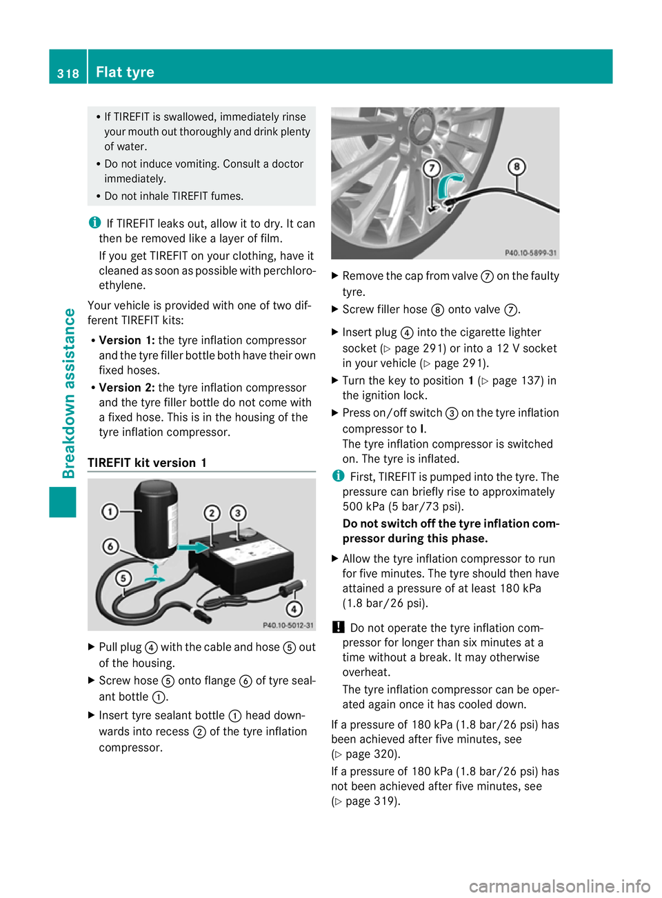
TIREFIT kit version 1 X
Pull plug ?with the cable and hose Aout
of the housing.
X Screw hose Aonto flange Bof tyre seal-
ant bottle :.
X Insert tyre sealant bottle :head down-
wards into recess ;of the tyre inflation
compressor. X
Remove the cap from valve Con the faulty
tyre.
X Screw filler hose Donto valve C.
X Insert plug ?into the cigarette lighter
socket (Y page 291) or into a 12 V socket
in your vehicle (Y page 291).
X Turn the key to position 1(Y page 137) in
the ignition lock.
X Press on/offs witch=on the tyre inflation
compressor to I.
The tyre inflatio ncompressor is switched
on. The tyre is inflated.
i First, TIREFIT is pumped into the tyre. The
pressure can briefly rise to approximately
500 kPa (5 bar/73 psi).
Do not switch off the tyre inflation com-
pressor during this phase.
X Allow the tyre inflation compressor to run
for five minutes. The tyre should then have
attained a pressure of at least 180 kPa
(1.8 bar/26 psi).
! Do not operate the tyre inflation com-
pressor for longer than six minutes at a
time without a break. It may otherwise
overheat.
The tyre inflation compressor can be oper-
ated again once it has cooled down.
If a pressure of 180 kPa (1.8 bar/26 psi) has
been achieved after five minutes, see
(Y page 320).
If a pressure of 180 kPa (1.8 bar/26 psi) has
not been achieved after five minutes, see
(Y page 319). 318
Flat tyreBreakdown assistance