2011 INFINITI QX56 display
[x] Cancel search: displayPage 4573 of 5598
SE-114
< REMOVAL AND INSTALLATION >
FRONT SEAT
SEATBACK
SEATBACK : Disassembly and AssemblyINFOID:0000000006217425
DISASSEMBLY
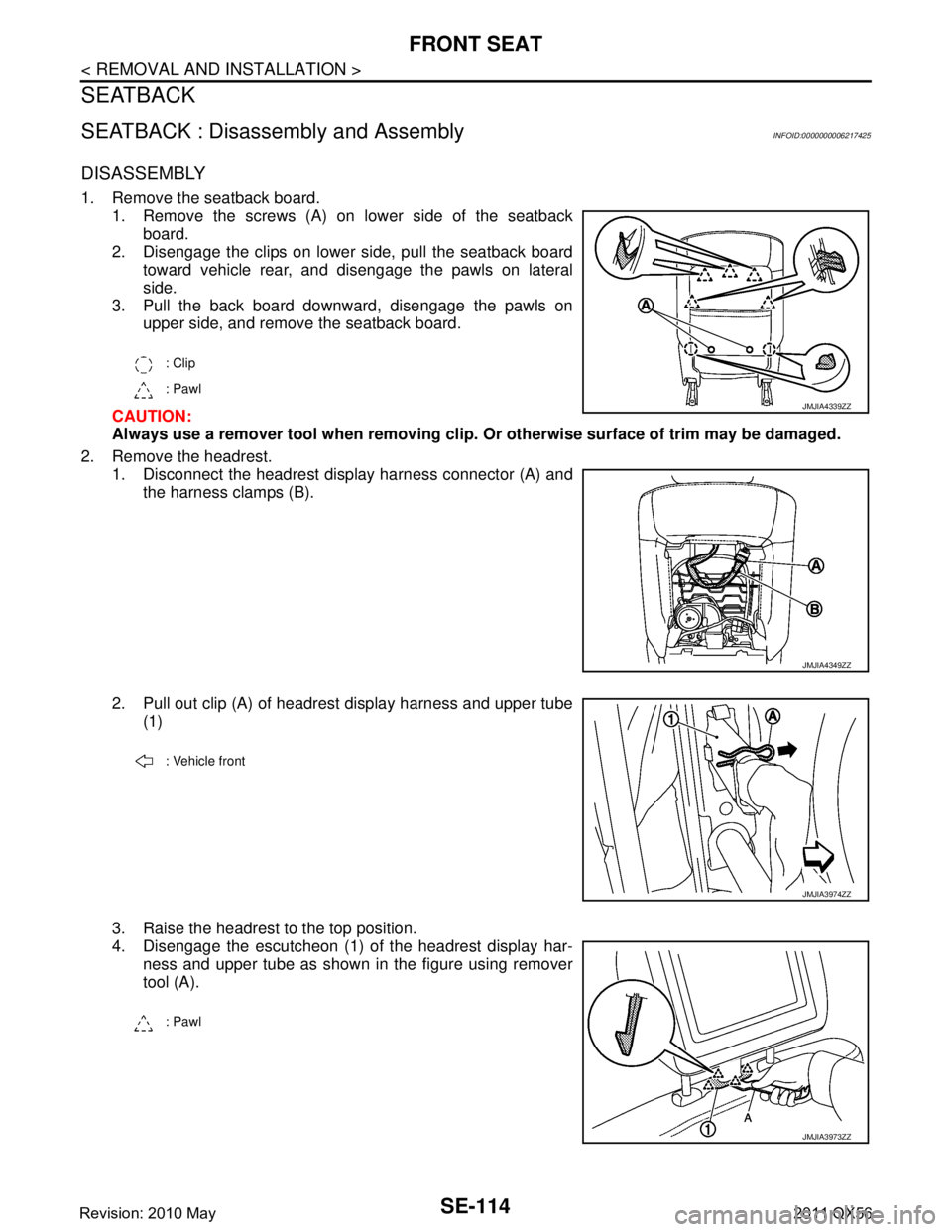
1. Remove the seatback board.1. Remove the screws (A) on lower side of the seatbackboard.
2. Disengage the clips on lower side, pull the seatback board toward vehicle rear, and disengage the pawls on lateral
side.
3. Pull the back board downward, disengage the pawls on upper side, and remove the seatback board.
CAUTION:
Always use a remover tool when removing clip. Or otherwise surface of trim may be damaged.
2. Remove the headrest. 1. Disconnect the headrest display harness connector (A) and
the harness clamps (B).
2. Pull out clip (A) of headrest display harness and upper tube (1)
3. Raise the headrest to the top position.
4. Disengage the escutcheon (1) of the headrest display har- ness and upper tube as shown in the figure using remover
tool (A).
: Clip
: Pawl
JMJIA4339ZZ
JMJIA4349ZZ
: Vehicle front
JMJIA3974ZZ
: Pawl
JMJIA3973ZZ
Revision: 2010 May2011 QX56
Page 4574 of 5598
FRONT SEATSE-115
< REMOVAL AND INSTALLATION >
C
DE
F
G H
I
K L
M A
B
SE
N
O P
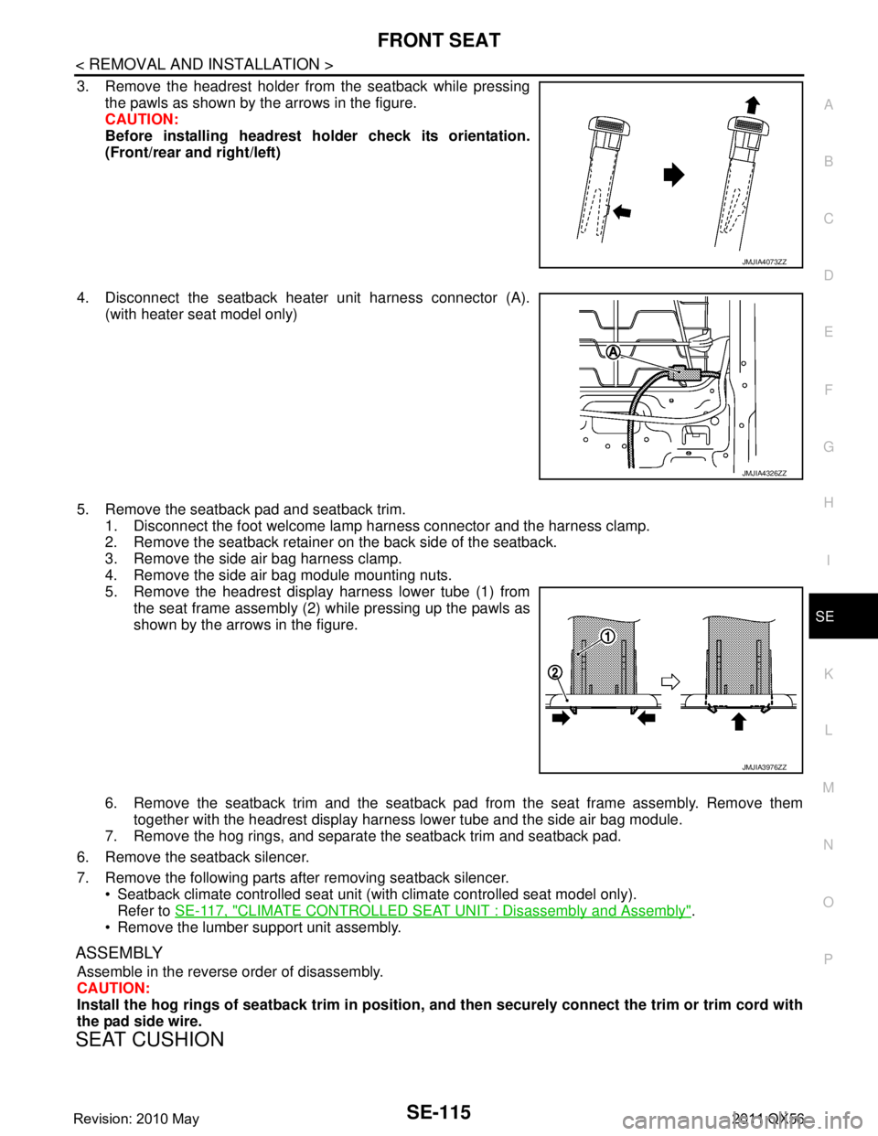
3. Remove the headrest holder from the seatback while pressing the pawls as shown by the arrows in the figure.
CAUTION:
Before installing headrest holder check its orientation.
(Front/rear and right/left)
4. Disconnect the seatback heater unit harness connector (A). (with heater seat model only)
5. Remove the seatback pad and seatback trim. 1. Disconnect the foot welcome lamp harness connector and the harness clamp.
2. Remove the seatback retainer on the back side of the seatback.
3. Remove the side air bag harness clamp.
4. Remove the side air bag module mounting nuts.
5. Remove the headrest display harness lower tube (1) from
the seat frame assembly (2) while pressing up the pawls as
shown by the arrows in the figure.
6. Remove the seatback trim and the seatback pad from the seat frame assembly. Remove them
together with the headrest display harness lower tube and the side air bag module.
7. Remove the hog rings, and separate the seatback trim and seatback pad.
6. Remove the seatback silencer.
7. Remove the following parts after removing seatback silencer. Seatback climate controlled seat unit (wit h climate controlled seat model only).
Refer to SE-117, "
CLIMATE CONTROLLED SEAT UNIT : Disassembly and Assembly".
Remove the lumber support unit assembly.
ASSEMBLY
Assemble in the reverse order of disassembly.
CAUTION:
Install the hog rings of seatback trim in position, and then securely connect the trim or trim cord with
the pad side wire.
SEAT CUSHION
JMJIA4073ZZ
JMJIA4326ZZ
JMJIA3976ZZ
Revision: 2010 May2011 QX56
Page 4576 of 5598
FRONT SEATSE-117
< REMOVAL AND INSTALLATION >
C
DE
F
G H
I
K L
M A
B
SE
N
O P
ASSEMBLY
Assemble in the reverse order of disassembly.
CAUTION:
Install the hog rings of seat cushion trim in positi on, and then securely connect the trim or trim cord
with the pad side wire.
CLIMATE CONTROLLED SEAT UNIT
CLIMATE CONTROLLED SEAT UNI T : Disassembly and AssemblyINFOID:0000000006217427
DISASSEMBLY
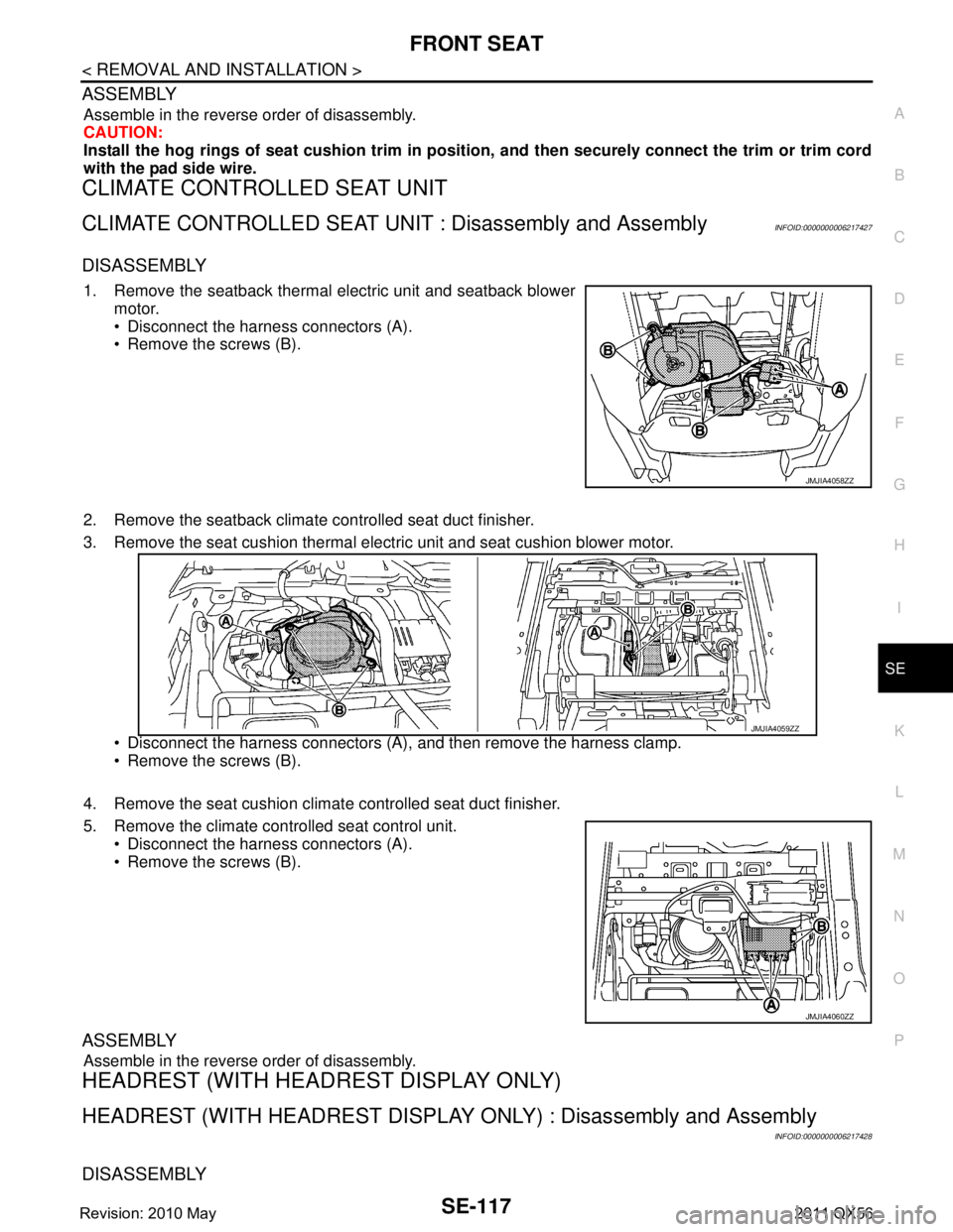
1. Remove the seatback thermal electric unit and seatback blower
motor.
Disconnect the harness connectors (A).
Remove the screws (B).
2. Remove the seatback climate controlled seat duct finisher.
3. Remove the seat cushion thermal electric unit and seat cushion blower motor.
Disconnect the harness connectors (A), and then remove the harness clamp.
Remove the screws (B).
4. Remove the seat cushion climat e controlled seat duct finisher.
5. Remove the climate controlled seat control unit. Disconnect the harness connectors (A).
Remove the screws (B).
ASSEMBLY
Assemble in the reverse order of disassembly.
HEADREST (WITH HEAD REST DISPLAY ONLY)
HEADREST (WITH HEADREST DISPLAY ONLY) : Disassembly and Assembly
INFOID:0000000006217428
DISASSEMBLY
JMJIA4058ZZ
JMJIA4059ZZ
JMJIA4060ZZ
Revision: 2010 May2011 QX56
Page 4577 of 5598
SE-118
< REMOVAL AND INSTALLATION >
FRONT SEAT
CAUTION:
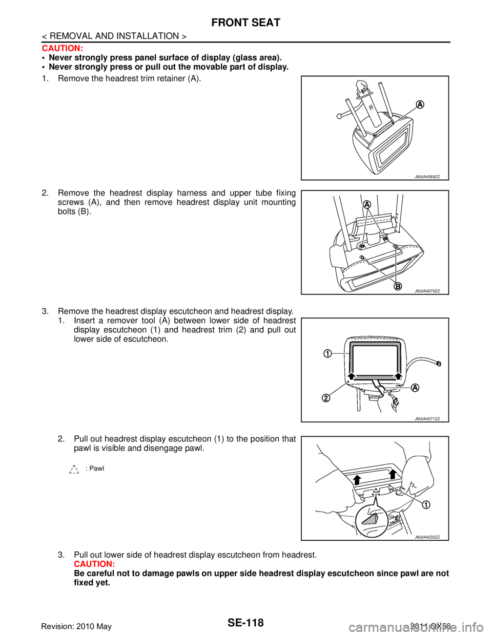
Never strongly press panel surface of display (glass area).
Never strongly press or pull out the movable part of display.
1. Remove the headrest trim retainer (A).
2. Remove the headrest display harness and upper tube fixingscrews (A), and then remove headrest display unit mounting
bolts (B).
3. Remove the headrest display escutcheon and headrest display. 1. Insert a remover tool (A) between lower side of headrest
display escutcheon (1) and headrest trim (2) and pull out
lower side of escutcheon.
2. Pull out headrest display escutcheon (1) to the position that pawl is visible and disengage pawl.
3. Pull out lower side of headrest display escutcheon from headrest. CAUTION:
Be careful not to damage pawls on upper side headrest display escutcheon since pawl are not
fixed yet.
JMJIA4069ZZ
JMJIA4070ZZ
JMJIA4071ZZ
: Pawl
JMJIA4232ZZ
Revision: 2010 May2011 QX56
Page 4578 of 5598
FRONT SEATSE-119
< REMOVAL AND INSTALLATION >
C
DE
F
G H
I
K L
M A
B
SE
N
O P
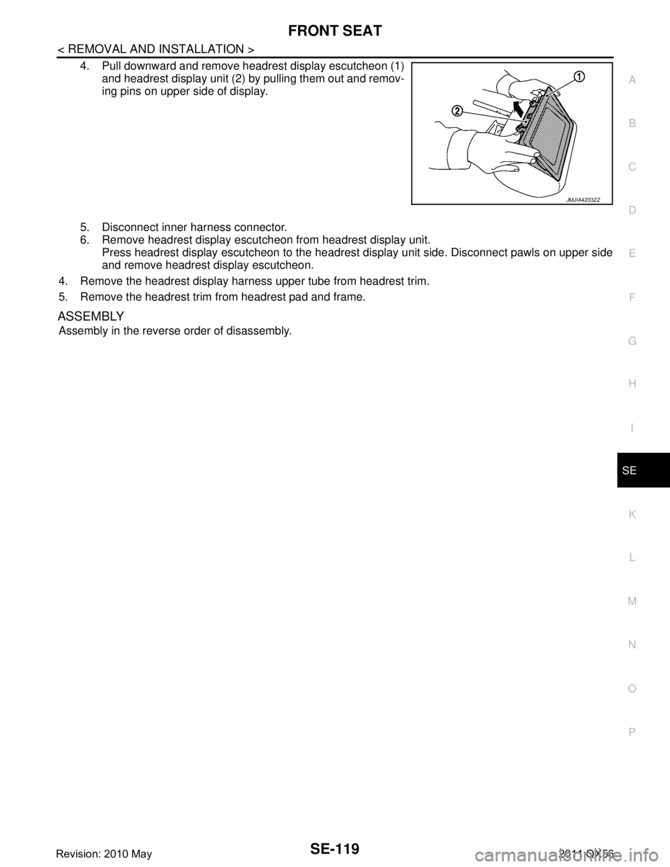
4. Pull downward and remove headrest display escutcheon (1) and headrest display unit (2) by pulling them out and remov-
ing pins on upper side of display.
5. Disconnect inner harness connector.
6. Remove headrest display escutcheon from headrest display unit. Press headrest display escutcheon to the headrest display unit side. Disconnect pawls on upper side
and remove headrest display escutcheon.
4. Remove the headrest display harness upper tube from headrest trim.
5. Remove the headrest trim from headrest pad and frame.
ASSEMBLY
Assembly in the reverse order of disassembly.
JMJIA4233ZZ
Revision: 2010 May2011 QX56
Page 4608 of 5598

SEC-1
BODY EXTERIOR, DOORS, ROOF & VEHICLE SECURITY
C
D
E
F
G H
I
J
L
M
SECTION SEC
A
B
SEC
N
O P
CONTENTS
SECURITY CONTROL SYSTEM
WITH INTELLIGE NT KEY SYSTEM
PRECAUTION ................ ...............................
5
PRECAUTIONS .............................................. .....5
Precaution for Supplemental Restraint System
(SRS) "AIR BAG" and "SEAT BELT PRE-TEN-
SIONER" ............................................................. ......
5
Precaution Necessary for Steering Wheel Rota-
tion after Battery Disconnect .....................................
5
Precaution for Procedure without Cowl Top Cover ......6
SYSTEM DESCRIPTION ..............................7
COMPONENT PARTS ................................... .....7
Component Parts Location .................................. ......7
Component Description .............................................8
A/T Shift Selector (Detention Switch) ........................8
BCM ..........................................................................8
ECM ..........................................................................9
IPDM E/R ..................................................................9
NATS Antenna Amp. .................................................9
TCM ..........................................................................9
Combination Meter ....................................................9
Door Switch ...............................................................9
Hood Switch ..............................................................9
Inside Key Antenna ...................................................9
Intelligent Key ............................................................9
Push-button Ignition Switch .....................................10
Remote Keyless Entry Receiver .............................10
Security Indicator Lamp ..........................................10
Starter Control Relay ...............................................10
Starter Relay ...........................................................10
Steering Lock Relay ................................................10
Steering Lock Unit ...................................................10
Stop Lamp Switch ...................................................10
Transmission Range Switch ....................................10
Vehicle Information Display .....................................11
SYSTEM .............................................................12
INTELLIGENT KEY SYSTEM/ENGINE START
FUNCTION ............................................................. ....
12
INTELLIGENT KEY SYSTEM/ENGINE START
FUNCTION : System Diagram ................................
12
INTELLIGENT KEY SYSTEM/ENGINE START
FUNCTION : System Description ............................
12
INFINITI VEHICLE IMMOBILIZER SYSTEM-NATS ....14
INFINITI VEHICLE IMMOBILIZER SYSTEM-
NATS : System Diagram .........................................
15
INFINITI VEHICLE IMMOBILIZER SYSTEM-
NATS : System Description .....................................
15
VEHICLE SECURITY SYSTEM .................................17
VEHICLE SECURITY SYSTEM : System Dia-
gram .................................................................... ....
17
VEHICLE SECURITY SYSTEM : System Descrip-
tion ...........................................................................
18
DIAGNOSIS SYSTEM (BCM) ...........................21
COMMON ITEM ..................................................... ....21
COMMON ITEM : CONSULT-III Function (BCM -
COMMON ITEM) .....................................................
21
INTELLIGENT KEY ................................................ ....22
INTELLIGENT KEY : CONSULT-III Function
(BCM - INTELLIGENT KEY) ....................................
22
THEFT ALM ........................................................... ....26
THEFT ALM : CONSULT-III Function (BCM -
THEFT) ................................................................ ....
26
IMMU ...................................................................... ....27
IMMU : CONSULT-III Function (BCM - IMMU) ........27
DIAGNOSIS SYSTEM (IPDM E/R) ...................28
CONSULT-III Function (IPDM E/R) .........................28
ECU DIAGNOSIS INFORMATION ..............30
ECM, IPDM E/R, BCM .......................................30
List of ECU Reference ......................................... ....30
Revision: 2010 May2011 QX56
Page 4615 of 5598
![INFINITI QX56 2011 Factory Service Manual
SEC-8
< SYSTEM DESCRIPTION >[WITH INTELLIGENT KEY SYSTEM]
COMPONENT PARTS
Component Description
INFOID:0000000006226152
A/T Shift Selector (Detention Switch)INFOID:0000000006226153
Detention switch INFINITI QX56 2011 Factory Service Manual
SEC-8
< SYSTEM DESCRIPTION >[WITH INTELLIGENT KEY SYSTEM]
COMPONENT PARTS
Component Description
INFOID:0000000006226152
A/T Shift Selector (Detention Switch)INFOID:0000000006226153
Detention switch](/manual-img/42/57033/w960_57033-4614.png)
SEC-8
< SYSTEM DESCRIPTION >[WITH INTELLIGENT KEY SYSTEM]
COMPONENT PARTS
Component Description
INFOID:0000000006226152
A/T Shift Selector (Detention Switch)INFOID:0000000006226153
Detention switch detects that A/T sh ift selector is in the P position, and then transmits the signal to BCM and
IPDM E/R.
BCM confirms the A/T shift selector position with the following 5 signals.
P position signal from A/T shift selector (detention switch)
P/N position signal from TCM
P position signal from IPDM E/R (CAN)
P/N position signal from IPDM E/R (CAN)
P/N position signal from TCM (CAN)
IPDM E/R confirms the A/T shift select or position with the following 3 signals.
P position signal from A/T shift selector (detention switch)
P/N position signal from TCM
P/N position signal from BCM (CAN)
BCMINFOID:0000000006226154
BCM controls INTELLIGENT KEY SYSTEM (ENGIN E START FUNCTION), INFINITI VEHICLE IMMOBI-
LIZER SYSTEM-NATS [IVIS (NATS)], and VEHICLE SECURITY SYSTEM.
BCM performs the ID verification between BCM and Intelligent Key when the Intelligent Key is carried into the
detection area of inside key antenna, and push-button ignition s witch is pressed. If the ID verification result is
OK, push-button ignition switch operation is available.
13. Front door swit ch (driver side)
Refer to DLK-11, "
DOOR LOCK
SYSTEM :
ComponentPartsLocation". 14. Remote keyless entry receiver
Refer to DLK-11, "
DOOR LOCK
SYSTEM :
ComponentPartsLocation". 15. Inside key antenna (luggage room)
Refer to DLK-11, "
DOOR LOCK
SYSTEM :
ComponentPartsLocation".
A. Behind push-button ignition switch
Component Reference
A/T shift selector (detention switch) SEC-8
BCMSEC-8
ECMSEC-9
IPDM E/RSEC-9
NATS antenna amp.SEC-9
TCMSEC-9
Combination meterSEC-9
Door switchSEC-9
Hood switchSEC-9
Inside key antennaSEC-9
Intelligent KeySEC-9
Push-button ignition switchSEC-10
Remote keyless entry receiverSEC-10
Security indicator lampSEC-10
Starter control relaySEC-10
Starter relaySEC-10
Steering lock relaySEC-10
Steering lock unitSEC-10
Stop lamp switchSEC-10
Transmission range switchSEC-10
Vehicle information display SEC-11
Revision: 2010 May2011 QX56
Page 4618 of 5598
![INFINITI QX56 2011 Factory Service Manual
COMPONENT PARTSSEC-11
< SYSTEM DESCRIPTION > [WITH INTELLIGENT KEY SYSTEM]
C
D
E
F
G H
I
J
L
M A
B
SEC
N
O P
P position signal from A/T shift selector (detention switch)
P/N position signal from INFINITI QX56 2011 Factory Service Manual
COMPONENT PARTSSEC-11
< SYSTEM DESCRIPTION > [WITH INTELLIGENT KEY SYSTEM]
C
D
E
F
G H
I
J
L
M A
B
SEC
N
O P
P position signal from A/T shift selector (detention switch)
P/N position signal from](/manual-img/42/57033/w960_57033-4617.png)
COMPONENT PARTSSEC-11
< SYSTEM DESCRIPTION > [WITH INTELLIGENT KEY SYSTEM]
C
D
E
F
G H
I
J
L
M A
B
SEC
N
O P
P position signal from A/T shift selector (detention switch)
P/N position signal from TCM
P/N position signal from BCM (CAN)
Vehicle Information DisplayINFOID:0000000006226176
Vehicle information display is integrated in combination meter.
Various information and warnings regarding to the Intelligent Key System are displayed.
Revision: 2010 May2011 QX56