2011 INFINITI QX56 BATTERY
[x] Cancel search: BATTERYPage 4481 of 5598

SE-22
< ECU DIAGNOSIS INFORMATION >
CLIMATE CONTROLLED SEAT CONTROL UNIT
Malfunction Malfunctioning condition
The temperature difference between the seatback ther-
mal electric unit and seat cushion thermal electric unit is
more than 30 °C When it detects for 4 seconds that the temperature difference between
the seatback thermal electric unit and seat cushion thermal electric unit
is more than 30 °, it stops the output to the thermal electric unit, activates
the climate controlled seat blower motor at the maximum position, and
sends the external airflow for 30 seconds
If the temperature difference is still more than 30 °C after 30 seconds
pass, it stops all output and enters the system OFF condition
When the temperature difference between seatback thermal electric unit and seat cushion thermal electric unit becomes less than 20 °C, the sys-
tem recovers automatically
If it detects that the temperature difference is more than 30 °C after the
automatic system recovery, it immediately stops all output and enters the
system OFF condition
NOTE:
When the switch operation is performed before entering the system OFF
condition, the fail-safe mode is reset.
The temperature of thermal electric unit is more than
11 0 °C in the HEAT mode (any thermal electric unit in the
seatback or seat cushion) When it detects for 4 seconds that the temperature of the thermal electric
unit is more than 110 °C, it stops the output to the thermal electric unit,
activates the climate controlled seat blower motor at the maximum posi-
tion, and sends the external airflow for 30 seconds
If the temperature does not become less than 105 °C after 30 seconds
pass, it stops all output and enters the system OFF condition
When the temperature of the thermal electric unit becomes less than 105 °C, the system recovers automatically
If it detects that the temperature of the thermal electric unit is more than
11 0 °C after the automatic system recovery, it immediately stops all out-
put and enters the system OFF condition
The temperature of the thermal electric unit is more than
45 °C in the COOL mode (any thermal electric unit in the
seatback or seat cushion) When it detects for 4 seconds that the temperature of the thermal electric
unit is more than 45 °C and less than 70 °C, it starts the temperature mon-
itoring of the thermal electric unit at 3 second intervals for increase in
temperature from the previous value
While monitoring, if it detects that the temperature continuously rises 2 °C
or more for 4 consecutive intervals or reaches 70 °C or more, it stops all
output and enters the system OFF condition
If it detects other results of monitoring, it continues activating in the se-
lected COOL mode
Thermal electric unit sensor open circuit
(in either the back and the cushion TEU) When it detects for 4 seconds that the thermal electric unit sensor is an
open circuit, it stops all output and enters the system OFF condition
Climate controlled seat blower motor system open circuit
(in either the back and the cushion blower) When it detects for 2 seconds that climate controlled seat blower motor
is an open circuit while the climate controlled seat is being activated, and
the battery status has been stable for the same 2 second period, it stops
output to the thermal electric unit
When it detects for 10 seconds that the climate controlled seat blower motor is an open circuit while the climate controlled seat is being activat-
ed, and the battery status has been stable for the same 10second period,
it stops all output and enters the system OFF condition
NOTE:
After detecting the climate seat blower motor system open circuit for 2
seconds, the system recovers automatically if the activation of the cli-
mate controlled seat blower motor is detected for 1 second or more.
Switch input out of the specified range
(either heat input or cool input) When it detects for 4 seconds that the rotary switch input is less than
30% of the vehicle battery voltage, it stops all output and enters the sys-
tem OFF condition
When the switch input returns to a value within the specified range, the
system recovers automatically
Revision: 2010 May2011 QX56
Page 4482 of 5598

CLIMATE CONTROLLED SEAT CONTROL UNITSE-23
< ECU DIAGNOSIS INFORMATION >
C
DE
F
G H
I
K L
M A
B
SE
N
O P
*: System voltage is the voltage between the climate controlled seat control unit power source and ground.
NOTE:
When the ignition status changes to OFF during the fail-safe mode, the control unit shall enter the OFF condition. If the ignit ion is turned
ON, the system shall return to the standby mode. If the system en ters in the fail-safe mode again after performing ignition cycle, start the
diagnosis. HEAT or COOL switch input out of the specified range
During the standby mode, heating or cooling states, if the rotary switch
input is less than 6% of the vehicle battery voltage, it stops all output and
enters the system OFF condition
When the switch input returns to a value within the specified range, the system recovers automatically
System voltage out of range If the system voltage at the climate controlled seat control unit falls out-
side of the 8.5 to 16.5 V operating range, it stops all output after a 500ms
time period.
When the system voltage returns to the normal operating range (10.5-
15.5V with a 500ms hysteresis), the system recovers automatically.
Malfunction Malfunctioning condition
Revision: 2010 May2011 QX56
Page 4526 of 5598
POWER SUPPLY AND GROUND CIRCUITSE-67
< DTC/CIRCUIT DIAGNOSIS >
C
DE
F
G H
I
K L
M A
B
SE
N
O P
DTC/CIRCUIT DIAGNOSIS
POWER SUPPLY AND GROUND CIRCUIT
CLIMATE CONTROLLED SEAT CONTROL UNIT
CLIMATE CONTROLLED SEAT CONT ROL UNIT : Diagnosis ProcedureINFOID:0000000006217389
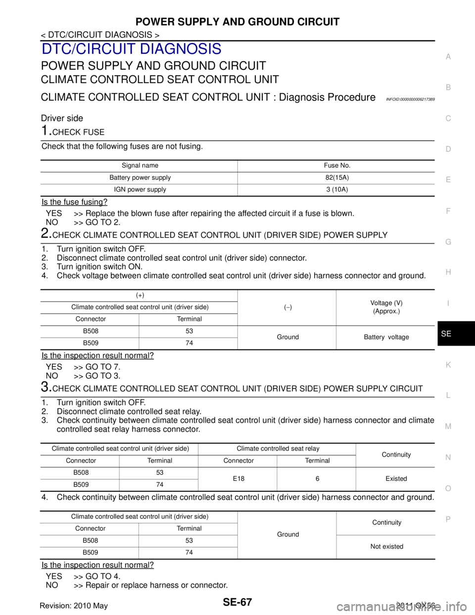
Driver side
1.CHECK FUSE
Check that the following fuses are not fusing.
Is the fuse fusing?
YES >> Replace the blown fuse after repairing the affected circuit if a fuse is blown.
NO >> GO TO 2.
2.CHECK CLIMATE CONTROLLED SEAT CONTRO L UNIT (DRIVER SIDE) POWER SUPPLY
1. Turn ignition switch OFF.
2. Disconnect climate controlled seat control unit (driver side) connector.
3. Turn ignition switch ON.
4. Check voltage between climate controlled seat c ontrol unit (driver side) harness connector and ground.
Is the inspection result normal?
YES >> GO TO 7.
NO >> GO TO 3.
3.CHECK CLIMATE CONTROLLED SEAT CONTROL UNI T (DRIVER SIDE) POWER SUPPLY CIRCUIT
1. Turn ignition switch OFF.
2. Disconnect climate controlled seat relay.
3. Check continuity between climate controlled seat control unit (driver side) harness connector and climate
controlled seat relay harness connector.
4. Check continuity between climate controlled seat control unit (driver side) harness connector and ground.
Is the inspection result normal?
YES >> GO TO 4.
NO >> Repair or replace harness or connector.
Signal name Fuse No.
Battery power supply 82(15A) IGN power supply 3 (10A)
(+) (− ) Voltage (V)
(Approx.)
Climate controlled seat co
ntrol unit (driver side)
Connector Terminal B508 53 Ground Battery voltage
B509 74
Climate controlled seat control unit (dri ver side) Climate controlled seat relay
Continuity
Connector Terminal Connector Terminal
B508 53 E18 6 Existed
B509 74
Climate controlled seat co ntrol unit (driver side)
GroundContinuity
Connector Terminal
B508 53 Not existed
B509 74
Revision: 2010 May2011 QX56
Page 4527 of 5598
SE-68
< DTC/CIRCUIT DIAGNOSIS >
POWER SUPPLY AND GROUND CIRCUIT
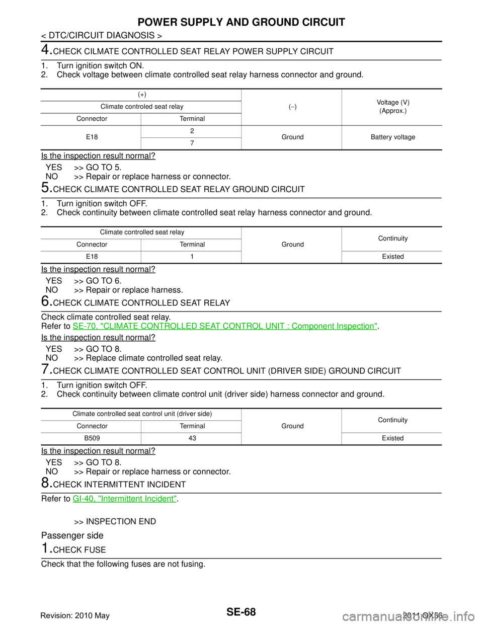
4.CHECK CILMATE CONTROLLED SEAT RELAY POWER SUPPLY CIRCUIT
1. Turn ignition switch ON.
2. Check voltage between climate controlled seat relay harness connector and ground.
Is the inspection result normal?
YES >> GO TO 5.
NO >> Repair or replace harness or connector.
5.CHECK CLIMATE CONTROLLED SEAT RELAY GROUND CIRCUIT
1. Turn ignition switch OFF.
2. Check continuity between climate cont rolled seat relay harness connector and ground.
Is the inspection result normal?
YES >> GO TO 6.
NO >> Repair or replace harness.
6.CHECK CLIMATE CONTROLLED SEAT RELAY
Check climate controlled seat relay.
Refer to SE-70, "
CLIMATE CONTROLLED SEAT CONTROL UNIT : Component Inspection".
Is the inspection result normal?
YES >> GO TO 8.
NO >> Replace climate controlled seat relay.
7.CHECK CLIMATE CONTROLLED SEAT CONTRO L UNIT (DRIVER SIDE) GROUND CIRCUIT
1. Turn ignition switch OFF.
2. Check continuity between climate contro l unit (driver side) harness connector and ground.
Is the inspection result normal?
YES >> GO TO 8.
NO >> Repair or replace harness or connector.
8.CHECK INTERMITTENT INCIDENT
Refer to GI-40, "
Intermittent Incident".
>> INSPECTION END
Passenger side
1.CHECK FUSE
Check that the following fuses are not fusing.
(+)
(− ) Voltage (V)
(Approx.)
Climate controled seat relay
Connector Terminal
E18 2
Ground Battery voltage
7
Climate controlled seat relay
GroundContinuity
Connector Terminal
E18 1 Existed
Climate controlled seat co ntrol unit (driver side)
GroundContinuity
Connector Terminal
B509 43 Existed
Revision: 2010 May2011 QX56
Page 4528 of 5598
POWER SUPPLY AND GROUND CIRCUITSE-69
< DTC/CIRCUIT DIAGNOSIS >
C
DE
F
G H
I
K L
M A
B
SE
N
O P
Is the fuse fusing?
YES >> Replace the blown fuse after repairing the affected circuit if a fuse is blown.
NO >> GO TO 2.
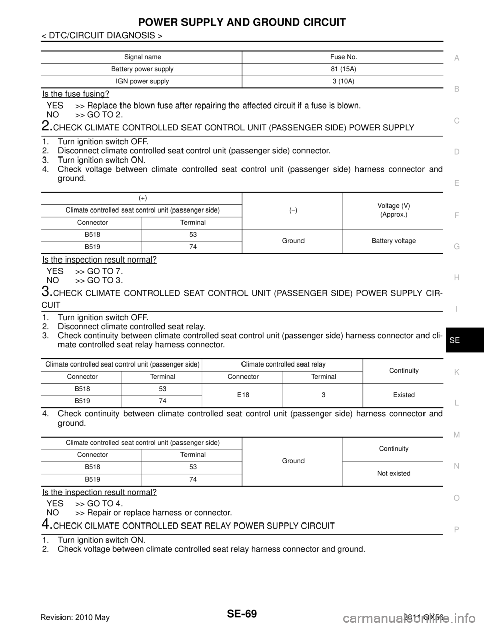
2.CHECK CLIMATE CONTROLLED SEAT CONTROL UNIT (PASSENGER SIDE) POWER SUPPLY
1. Turn ignition switch OFF.
2. Disconnect climate controlled seat c ontrol unit (passenger side) connector.
3. Turn ignition switch ON.
4. Check voltage between climate controlled seat control unit (passenger side) harness connector and
ground.
Is the inspection result normal?
YES >> GO TO 7.
NO >> GO TO 3.
3.CHECK CLIMATE CONTROLLED SEAT CONTROL UNI T (PASSENGER SIDE) POWER SUPPLY CIR-
CUIT
1. Turn ignition switch OFF.
2. Disconnect climate controlled seat relay.
3. Check continuity between climate controlled seat control unit (passenger side) harness connector and cli-
mate controlled seat relay harness connector.
4. Check continuity between climate controlled seat control unit (passenger side) harness connector and
ground.
Is the inspection result normal?
YES >> GO TO 4.
NO >> Repair or replace harness or connector.
4.CHECK CILMATE CONTROLLED SEAT RELAY POWER SUPPLY CIRCUIT
1. Turn ignition switch ON.
2. Check voltage between climate controll ed seat relay harness connector and ground.
Signal name Fuse No.
Battery power supply 81 (15A) IGN power supply 3 (10A)
(+) (− ) Voltage (V)
(Approx.)
Climate controlled seat control unit (passenger side)
Connector TerminalB518 53 Ground Battery voltage
B519 74
Climate controlled seat control unit (passenger side) Climate controlled seat relay Continuity
Connector Terminal Connector Terminal
B518 53 E18 3 Existed
B519 74
Climate controlled seat control unit (passenger side)
GroundContinuity
Connector Terminal
B518 53 Not existed
B519 74
Revision: 2010 May2011 QX56
Page 4529 of 5598
SE-70
< DTC/CIRCUIT DIAGNOSIS >
POWER SUPPLY AND GROUND CIRCUIT
Is the inspection result normal?
YES >> GO TO 5.
NO >> Repair or replace harness or connector.
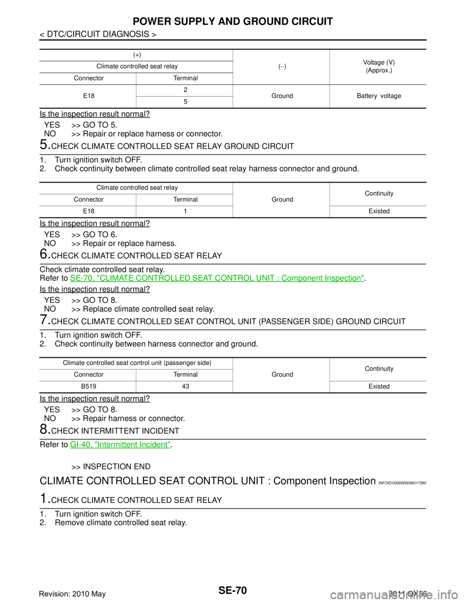
5.CHECK CLIMATE CONTROLLED SEAT RELAY GROUND CIRCUIT
1. Turn ignition switch OFF.
2. Check continuity between climate cont rolled seat relay harness connector and ground.
Is the inspection result normal?
YES >> GO TO 6.
NO >> Repair or replace harness.
6.CHECK CLIMATE CONTROLLED SEAT RELAY
Check climate controlled seat relay.
Refer to SE-70, "
CLIMATE CONTROLLED SEAT CONTROL UNIT : Component Inspection".
Is the inspection result normal?
YES >> GO TO 8.
NO >> Replace climate controlled seat relay.
7.CHECK CLIMATE CONTROLLED SEAT CONTRO L UNIT (PASSENGER SIDE) GROUND CIRCUIT
1. Turn ignition switch OFF.
2. Check continuity between harness connector and ground.
Is the inspection result normal?
YES >> GO TO 8.
NO >> Repair harness or connector.
8.CHECK INTERMITTENT INCIDENT
Refer to GI-40, "
Intermittent Incident".
>> INSPECTION END
CLIMATE CONTROLLED SEAT CONTRO L UNIT : Component InspectionINFOID:0000000006217390
1.CHECK CLIMATE CONTROLLED SEAT RELAY
1. Turn ignition switch OFF.
2. Remove climate controlled seat relay.
(+)
(− ) Voltage (V)
(Approx.)
Climate controlled seat relay
Connector Terminal
E18 2
Ground Battery voltage
5
Climate controlled seat relay
GroundContinuity
Connector Terminal
E18 1 Existed
Climate controlled seat control unit (passenger side) GroundContinuity
Connector Terminal
B519 43 Existed
Revision: 2010 May2011 QX56
Page 4572 of 5598
FRONT SEATSE-113
< REMOVAL AND INSTALLATION >
C
DE
F
G H
I
K L
M A
B
SE
N
O P
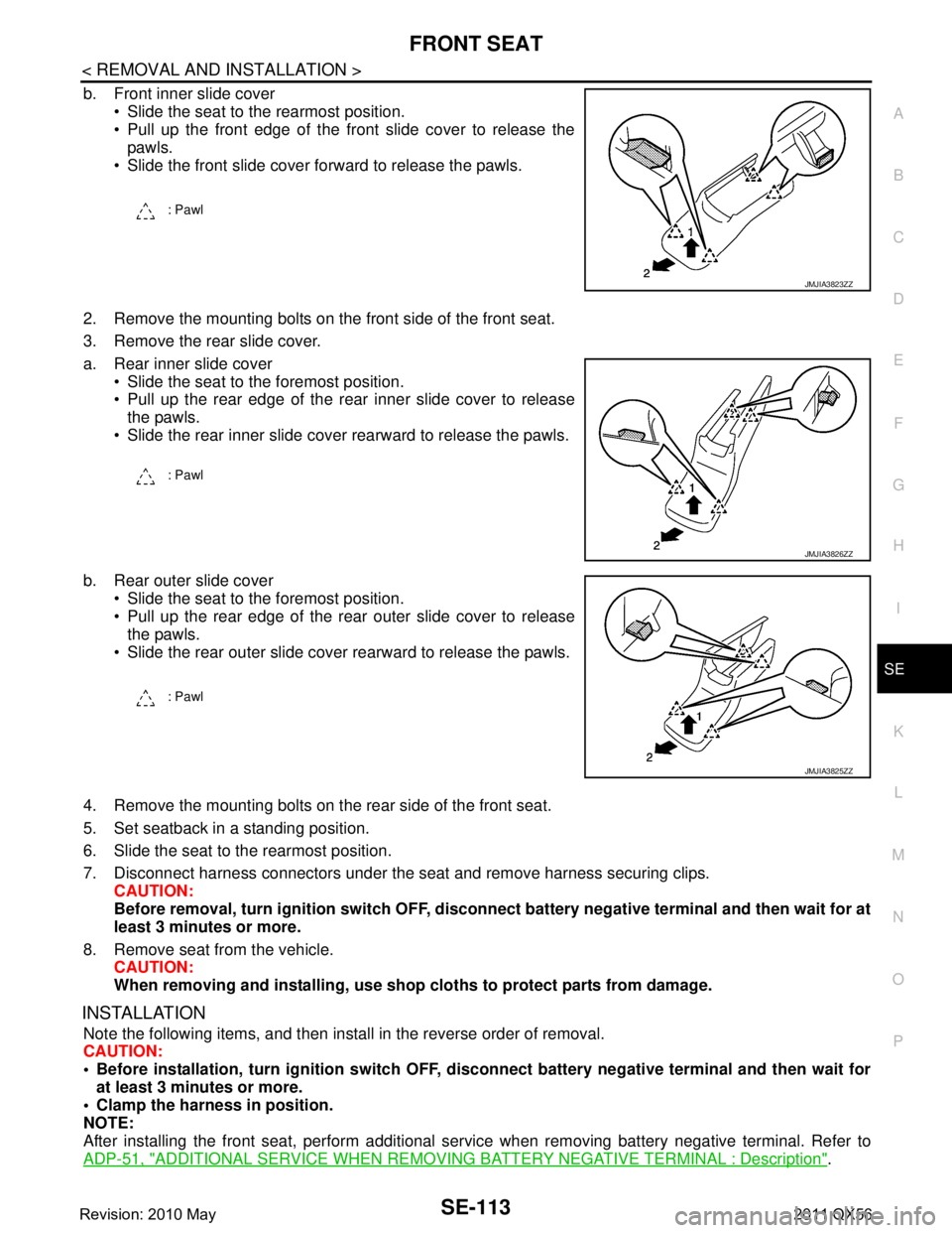
b. Front inner slide cover Slide the seat to the rearmost position.
Pull up the front edge of the front slide cover to release thepawls.
Slide the front slide cover forward to release the pawls.
2. Remove the mounting bolts on the front side of the front seat.
3. Remove the rear slide cover.
a. Rear inner slide cover Slide the seat to the foremost position.
Pull up the rear edge of the rear inner slide cover to releasethe pawls.
Slide the rear inner slide cover rearward to release the pawls.
b. Rear outer slide cover Slide the seat to the foremost position.
Pull up the rear edge of the rear outer slide cover to releasethe pawls.
Slide the rear outer slide cover rearward to release the pawls.
4. Remove the mounting bolts on t he rear side of the front seat.
5. Set seatback in a standing position.
6. Slide the seat to the rearmost position.
7. Disconnect harness connectors under the seat and remove harness securing clips. CAUTION:
Before removal, turn ignition sw itch OFF, disconnect battery negative terminal and then wait for at
least 3 minutes or more.
8. Remove seat from the vehicle. CAUTION:
When removing and installing, use shop cloths to protect parts from damage.
INSTALLATION
Note the following items, and then install in the reverse order of removal.
CAUTION:
Before installation, turn ignition switch OFF, disconnect battery ne gative terminal and then wait for
at least 3 minutes or more.
Clamp the harness in position.
NOTE:
After installing the front seat, perform additional serv ice when removing battery negative terminal. Refer to
ADP-51, "
ADDITIONAL SERVICE WHEN REMOVING BATTERY NEGATIVE TERMINAL : Description".
: Pawl
JMJIA3823ZZ
: Pawl
JMJIA3826ZZ
: Pawl
JMJIA3825ZZ
Revision: 2010 May2011 QX56
Page 4608 of 5598

SEC-1
BODY EXTERIOR, DOORS, ROOF & VEHICLE SECURITY
C
D
E
F
G H
I
J
L
M
SECTION SEC
A
B
SEC
N
O P
CONTENTS
SECURITY CONTROL SYSTEM
WITH INTELLIGE NT KEY SYSTEM
PRECAUTION ................ ...............................
5
PRECAUTIONS .............................................. .....5
Precaution for Supplemental Restraint System
(SRS) "AIR BAG" and "SEAT BELT PRE-TEN-
SIONER" ............................................................. ......
5
Precaution Necessary for Steering Wheel Rota-
tion after Battery Disconnect .....................................
5
Precaution for Procedure without Cowl Top Cover ......6
SYSTEM DESCRIPTION ..............................7
COMPONENT PARTS ................................... .....7
Component Parts Location .................................. ......7
Component Description .............................................8
A/T Shift Selector (Detention Switch) ........................8
BCM ..........................................................................8
ECM ..........................................................................9
IPDM E/R ..................................................................9
NATS Antenna Amp. .................................................9
TCM ..........................................................................9
Combination Meter ....................................................9
Door Switch ...............................................................9
Hood Switch ..............................................................9
Inside Key Antenna ...................................................9
Intelligent Key ............................................................9
Push-button Ignition Switch .....................................10
Remote Keyless Entry Receiver .............................10
Security Indicator Lamp ..........................................10
Starter Control Relay ...............................................10
Starter Relay ...........................................................10
Steering Lock Relay ................................................10
Steering Lock Unit ...................................................10
Stop Lamp Switch ...................................................10
Transmission Range Switch ....................................10
Vehicle Information Display .....................................11
SYSTEM .............................................................12
INTELLIGENT KEY SYSTEM/ENGINE START
FUNCTION ............................................................. ....
12
INTELLIGENT KEY SYSTEM/ENGINE START
FUNCTION : System Diagram ................................
12
INTELLIGENT KEY SYSTEM/ENGINE START
FUNCTION : System Description ............................
12
INFINITI VEHICLE IMMOBILIZER SYSTEM-NATS ....14
INFINITI VEHICLE IMMOBILIZER SYSTEM-
NATS : System Diagram .........................................
15
INFINITI VEHICLE IMMOBILIZER SYSTEM-
NATS : System Description .....................................
15
VEHICLE SECURITY SYSTEM .................................17
VEHICLE SECURITY SYSTEM : System Dia-
gram .................................................................... ....
17
VEHICLE SECURITY SYSTEM : System Descrip-
tion ...........................................................................
18
DIAGNOSIS SYSTEM (BCM) ...........................21
COMMON ITEM ..................................................... ....21
COMMON ITEM : CONSULT-III Function (BCM -
COMMON ITEM) .....................................................
21
INTELLIGENT KEY ................................................ ....22
INTELLIGENT KEY : CONSULT-III Function
(BCM - INTELLIGENT KEY) ....................................
22
THEFT ALM ........................................................... ....26
THEFT ALM : CONSULT-III Function (BCM -
THEFT) ................................................................ ....
26
IMMU ...................................................................... ....27
IMMU : CONSULT-III Function (BCM - IMMU) ........27
DIAGNOSIS SYSTEM (IPDM E/R) ...................28
CONSULT-III Function (IPDM E/R) .........................28
ECU DIAGNOSIS INFORMATION ..............30
ECM, IPDM E/R, BCM .......................................30
List of ECU Reference ......................................... ....30
Revision: 2010 May2011 QX56