2011 INFINITI QX56 warning
[x] Cancel search: warningPage 4806 of 5598

SYSTEMSRC-13
< SYSTEM DESCRIPTION >
C
DE
F
G
I
J
K L
M A
B
SRC
N
O P
Operation of air bag diagnosis sensor unit when air bag diagnosis sensor unit receives information from Occupant Detection System.
Even if zero point reset is “complete”, always perfo rm zero point reset after the removal and installation of
seat or the removal of control unit harness connector.
Status (front passenger
seat) Passenger air bag Front passenger air
bag OFF indicatorAir bag warning lamp
Seat belt warning lamp
(when front passenger
seat is unbuckled)
Empty Suppress OFF OFF OFF
An object Suppress ON OFF OFF
Child/ child-seat Suppress ON OFF ON
Adult Enable to deploy OFF OFF ON
Malfunction Suppress ON Blinking OFF
Zero point reset
Not yet performed (NIS-
SAN genuine parts
only) Suppress ON Blinking OFF
Revision: 2010 May2011 QX56
Page 4807 of 5598

SRC-14
< SYSTEM DESCRIPTION >
DIAGNOSIS SYSTEM (AIR BAG)
DIAGNOSIS SYSTEM (AIR BAG)
DescriptionINFOID:0000000006219952
CAUTION:
Never use electrical test equipment on any circuit related to the SRS unless instructed in this Ser-
vice Manual. SRS wiring harnesses can be identifi ed by yellow and/or orange harnesses or harness
connectors.
Never repair, splice or modify the SRS wiring harn ess. If the harness is damaged, replace it with a
new one.
Keep ground portion clean.
DIAGNOSIS FUNCTION
The SRS self-diagnostic results can be read with air bag warning lamp and/or CONSULT-III.
The user mode is exclusively prepared for the customer (driver). This mode warns the driver of a system
malfunction through the operation of the air bag warning lamp.
The diagnosis mode allows the technician to locate and inspect the malfunctioning part.
The mode applications for the air bag warning lamp and CONSULT-III are as per the following items.
× : Application, —: Not application
On Board Diagn osis FunctionINFOID:0000000006219953
ON-BOARD DIAGNOSIS
There are two self diagnosis functions with air bag warning lamp per the following items.
USER MODE
DIAGNOSIS MODE
METHOD OF STARTING
Diagnosis mode changes from user mode to di agnosis mode when changing operation is performed.
In user mode, when SRS air bag warning lamp is not blinking, changing to diagnosis mode by ignition switch
operation is not possible.
In diagnosis mode, when repair is complete and system is normal, the mode changes to user mode when
ignition switch is turned from OFF to ON.
Procedure to Change Diagnosis Mode
1. Turn ignition switch from OFF to ON.
2. SRS air bag lamp turns ON for 7 second and turns OFF, then turn ignition switch OFF within 1second after the lamp turns OFF.
3. After turning ignition switch OFF, wait for 3 seconds or more.
4. Repeat operation 1 to 3 for 2 times so that operation 1 to 3 is repeated for 3times in total.
5. Turn ignition switch from OFF to ON. Diagnosis mode changes.
USER MODE
In USER MODE, air bag warning lamp on combination meter blinks when a malfunction is detected and warns
the customer (driver).
How to Read Air Bag Warning Lamp
1. Turn the ignition switch from OFF to ON, and check that the air bag warning lamp blinks.
2. Compare the air bag warning lamp blinking pattern with the examples.
Air Bag Warning Lamp Examples
Diagnosis tool User mode Diagnosis mode
Air bag warning lamp ××
CONSULT-III – ×
Revision: 2010 May2011 QX56
Page 4808 of 5598
DIAGNOSIS SYSTEM (AIR BAG)SRC-15
< SYSTEM DESCRIPTION >
C
DE
F
G
I
J
K L
M A
B
SRC
N
O P
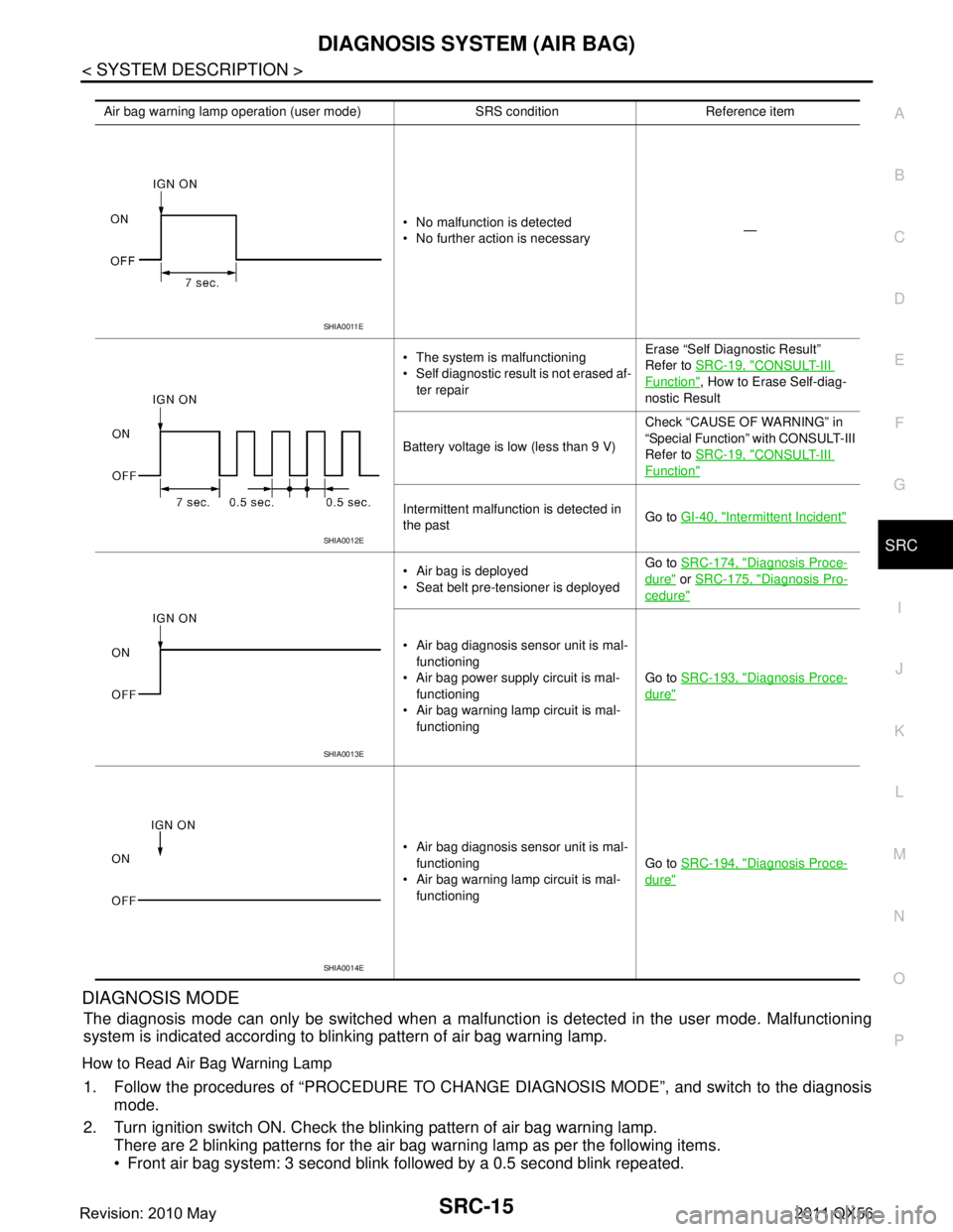
DIAGNOSIS MODE
The diagnosis mode can only be switched when a malfuncti on is detected in the user mode. Malfunctioning
system is indicated according to blinking pattern of air bag warning lamp.
How to Read Air Bag Warning Lamp
1. Follow the procedures of “PROCEDURE TO CHANG E DIAGNOSIS MODE”, and switch to the diagnosis
mode.
2. Turn ignition switch ON. Check the blinking pattern of air bag warning lamp. There are 2 blinking patterns for the air bag warning lamp as per the following items.
Front air bag system: 3 second blink followed by a 0.5 second blink repeated.
Air bag warning lamp operation (user mode) SRS condition Reference item
No malfunction is detected
No further action is necessary —
The system is malfunctioning
Self diagnostic result is not erased af- ter repair Erase “Self Diagnostic Result”
Refer to
SRC-19, "
CONSULT-III
Function", How to Erase Self-diag-
nostic Result
Battery voltage is low (less than 9 V) Check “CAUSE OF WARNING” in
“Special Function” with CONSULT-III
Refer to
SRC-19, "
CONSULT-III
Function"
Intermittent malfunction is detected in
the past Go to
GI-40, "Intermittent Incident"
Air bag is deployed
Seat belt pre-tensioner is deployed Go to
SRC-174, "Diagnosis Proce-
dure" or SRC-175, "Diagnosis Pro-
cedure"
Air bag diagnosis sensor unit is mal-
functioning
Air bag power supply circuit is mal- functioning
Air bag warning lamp circuit is mal-
functioning Go to
SRC-193, "
Diagnosis Proce-
dure"
Air bag diagnosis sensor unit is mal-
functioning
Air bag warning lamp circuit is mal- functioning Go to
SRC-194, "
Diagnosis Proce-
dure"
SHIA0011E
SHIA0012E
SHIA0013E
SHIA0014E
Revision: 2010 May2011 QX56
Page 4811 of 5598
SRC-18
< SYSTEM DESCRIPTION >
DIAGNOSIS SYSTEM (AIR BAG)
How to Erase Self-diagnostic Result
After a malfunction is repaired, turn the ignition swit ch OFF for one second or more, then turn ignition switch
ON. The diagnosis mode returns to the user mode. At that time the self-diagnostic result is cleared.
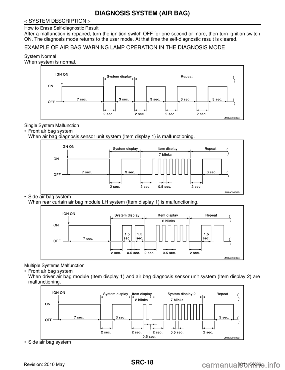
EXAMPLE OF AIR BAG WARNING LAMP OPERATION IN THE DIAGNOSIS MODE
System Normal
When system is normal.
Single System Malfunction
Front air bag system
When air bag diagnosis sensor unit system (Item display 1) is malfunctioning.
Side air bag system When rear curtain air bag module LH syst em (Item display 1) is malfunctioning.
Multiple Systems Malfunction
Front air bag system
When driver air bag module (Item display 1) and air bag diagnosis sensor unit system (Item display 2) are
malfunctioning.
Side air bag system
JMHIA0945GB
JMHIA0946GB
JMHIA0948GB
JMHIA0947GB
Revision: 2010 May2011 QX56
Page 4812 of 5598
DIAGNOSIS SYSTEM (AIR BAG)SRC-19
< SYSTEM DESCRIPTION >
C
DE
F
G
I
J
K L
M A
B
SRC
N
O P
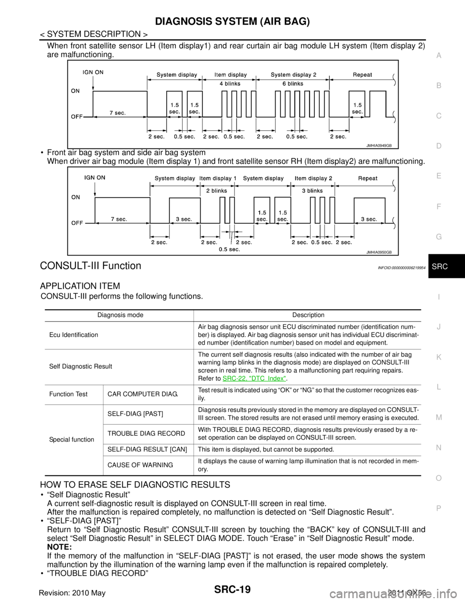
When front satellite sensor LH (Item display1) and r ear curtain air bag module LH system (Item display 2)
are malfunctioning.
Front air bag system and side air bag system When driver air bag module (Item display 1) and front satellite sensor RH (Item display2) are malfunctioning.
CONSULT-III FunctionINFOID:0000000006219954
APPLICATION ITEM
CONSULT-III performs the following functions.
HOW TO ERASE SELF DIAGNOSTIC RESULTS
“Self Diagnostic Result”
A current self-diagnostic result is displayed on CONSULT-III screen in real time.
After the malfunction is repaired completely, no malfunction is detected on “Self Diagnostic Result”.
“SELF-DIAG [PAST]” Return to “Self Diagnostic Result” CONSULT-III scr een by touching the “BACK” key of CONSULT-III and
select “Self Diagnostic Result” in SELECT DIAG MO DE. Touch “Erase” in “Self Diagnostic Result” mode.
NOTE:
If the memory of the malfunction in “SELF-DIAG [P AST]” is not erased, the user mode shows the system
malfunction by the illumination of the warning lamp even if the malfunction is repaired completely.
“TROUBLE DIAG RECORD”
JMHIA0949GB
JMHIA0950GB
Diagnosis mode Description
Ecu Identification Air bag diagnosis sensor unit ECU discriminated number (identification num-
ber) is displayed. Air bag diagnosis sensor unit has individual ECU discriminat-
ed number (identification number) based on model and equipment.
Self Diagnostic Result The current self diagnosis results (also indicated with the number of air bag
warning lamp blinks in the diagnosis mode) are displayed on CONSULT-III
screen in real time. This refers to a malfunctioning part requiring repairs.
Refer to
SRC-22, "
DTCIndex".
Function Test CAR COMPUTER DIAG. Test result is indicated using “OK” or “NG” so that the customer recognizes eas-
ily.
Special function SELF-DIAG [PAST]
Diagnosis results previously stored in the memory are displayed on CONSULT-
III screen. The stored results are not erased until memory erasing is executed.
TROUBLE DIAG RECORD With TROUBLE DIAG RECORD, diagnosis results previously erased by a re-
set operation can be displayed on CONSULT-III screen.
SELF-DIAG RESULT [CAN] This item is displayed, but cannot be supported.
CAUSE OF WARNING It displays the cause of warning lamp illumination that is not recorded in mem-
ory.
Revision: 2010 May2011 QX56
Page 4813 of 5598
![INFINITI QX56 2011 Factory Service Manual
SRC-20
< SYSTEM DESCRIPTION >
DIAGNOSIS SYSTEM (AIR BAG)
The memory of “TROUBLE DIAG RECORD” cannot be erased.
“SELF-DIAG RESULT [CAN]” Self-diagnosis result other than “SELF-DIAG R ESULT INFINITI QX56 2011 Factory Service Manual
SRC-20
< SYSTEM DESCRIPTION >
DIAGNOSIS SYSTEM (AIR BAG)
The memory of “TROUBLE DIAG RECORD” cannot be erased.
“SELF-DIAG RESULT [CAN]” Self-diagnosis result other than “SELF-DIAG R ESULT](/manual-img/42/57033/w960_57033-4812.png)
SRC-20
< SYSTEM DESCRIPTION >
DIAGNOSIS SYSTEM (AIR BAG)
The memory of “TROUBLE DIAG RECORD” cannot be erased.
“SELF-DIAG RESULT [CAN]” Self-diagnosis result other than “SELF-DIAG R ESULT [CAN]” is erased when touching “Erase”.
SPECIAL FUNCTION
CAUSE OF WARNING (AIR BAG)
This item indicates IGN low or high voltage condition.
The air bag warning lamp blink in user mode when the battery voltage is lowered to the voltage value (less
than 9 V or highroad to the voltage value (more than 16V ) at which the SRS cannot be operated normally. The
air bag warning lamp turns OFF after the battery voltage returns to normal status after blinking.
In such a case, the DTC memory is not performed and changing to the self-diagnostic mode by IGN operation
cannot be performed while the air bag warning lamp illumi nates. “NO DTC” is displayed even if the malfunc-
tioning parts are checked by CONSULT-III.
This function records the following items.
CAUSE OF WARNING (OCCUPANT DETSCTION SYSTEM)
Detection status and detection record is displayed w hen air bag warning lamp blinks due to occupant detec-
tion function stop. Change to trouble diagnosis mode by ignition switch is not possible while warning lamp is
blinking due to occupant detection function stop. “NO DT C” is displayed even if the malfunctioning parts are
checked by CONSULT-III.
Display contents of CONSULT-III Description
Air bag IGN VOLT COND
“LOW” is displayed when IGN low or high voltage is detected. If not, “OK” is
displayed.
IGN VOLT TIME Number of times of IGN low or high voltage is detected.
LOW V RECORED Number of times of IGN ON after IGN low or high voltage is detected at first.
Display contents of CONSULT-III Description
Occupant detection
system FUNCTION STATUS
“ON” or “STOP” is displayed according to occupant detection status that
is recognized by occupant detection system control unit.
“STOP” is displayed when occupant detection function is stopped, if not, “ON” is displayed.
STOP DETECTION Displays number of times occupant detection function stop which is detect-
ed by occupant detection system control unit is displayed.
DETECTION RECORD Displays number of times of IGN ON since first detection of occupant detec-
tion function stop is displayed.
Revision: 2010 May2011 QX56
Page 4815 of 5598
SRC-22
< ECU DIAGNOSIS INFORMATION >
DIAGNOSIS SENSOR UNIT
ECU DIAGNOSIS INFORMATION
DIAGNOSIS SENSOR UNIT
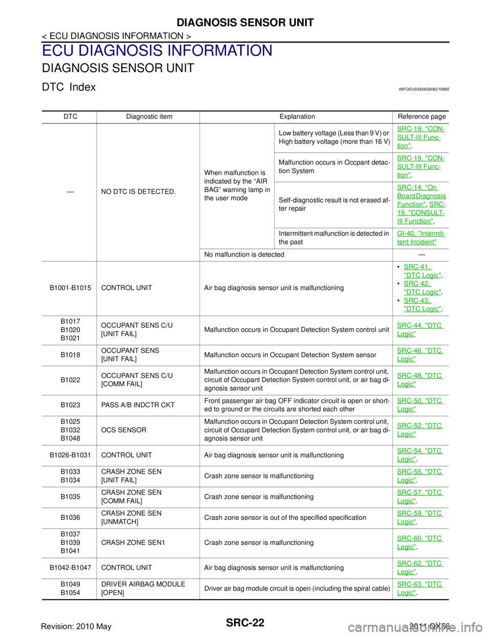
DTC IndexINFOID:0000000006219956
DTC Diagnostic item Explanation Reference page— NO DTC IS DETECTED. When malfunction is
indicated by the “AIR
BAG” warning lamp in
the user modeLow battery voltage (Less than 9 V) or
High battery voltage (more than 16 V)
SRC-19, "
CON-
SULT-III Func-
tion".
Malfunction occurs in Occpant detac-
tion System SRC-19, "
CON-
SULT-III Func-
tion".
Self-diagnostic result is not erased af-
ter repair SRC-14, "
On
Board Diagnosis
Function",
SRC-
19, "CONSULT-
III Function".
Intermittent malfunction is detected in
the past GI-40, "
Intermit-
tent Incident"
No malfunction is detected —
B1001-B1015 CONTROL UNIT Air bag diagnosis sensor unit is malfunctioning
SRC-41,
"DTC Logic".
SRC-42,
"DTC Logic".
SRC-43,
"DTC Logic".
B1017
B1020
B1021 OCCUPANT SENS C/U
[UNIT FAIL]
Malfunction occurs in Occupant Detection System control unit SRC-44, "
DTC
Logic"
B1018OCCUPANT SENS
[UNIT FAIL]
Malfunction occurs in Occupant Detection System sensor SRC-46, "DTC
Logic"
B1022OCCUPANT SENS C/U
[COMM FAIL] Malfunction occurs in Occupant Detection System control unit,
circuit of Occupant Detection System control unit, or air bag di-
agnosis sensor unit SRC-48, "DTC
Logic"
B1023 PASS A/B INDCTR CKT
Front passenger air bag OFF indicator circuit is open or short-
ed to ground or the circuits are shorted each other SRC-50, "DTC
Logic"
B1025
B1032
B1048
OCS SENSOR Malfunction occurs in Occupant Detection System control unit,
circuit of Occupant Detection System control unit, or air bag di-
agnosis sensor unit SRC-52, "DTC
Logic"
B1026-B1031 CONTROL UNIT Air bag diagnosis sensor unit is malfunctioning
SRC-54, "DTC
Logic".
B1033
B1034 CRASH ZONE SEN
[UNIT FAIL]
Crash zone sensor is malfunctioning
SRC-55, "
DTC
Logic".
B1035 CRASH ZONE SEN
[COMM FAIL] Crash zone sensor is malfunctioning SRC-57, "
DTC
Logic".
B1036 CRASH ZONE SEN
[UNMATCH]
Crash zone sensor is out of the specified specification SRC-59, "
DTC
Logic".
B1037
B1039
B1041 CRASH ZONE SEN1 Crash zone
sensor is malfunctioning SRC-60, "
DTC
Logic".
B1042-B1047 CONTROL UNIT Air bag diagnosis sensor unit is malfunctioning SRC-62, "
DTC
Logic".
B1049
B1054 DRIVER AIRBAG MODULE
[OPEN]
Driver air bag module circuit is open (including the spiral cable)
SRC-63, "
DTC
Logic".
Revision: 2010 May2011 QX56
Page 4830 of 5598
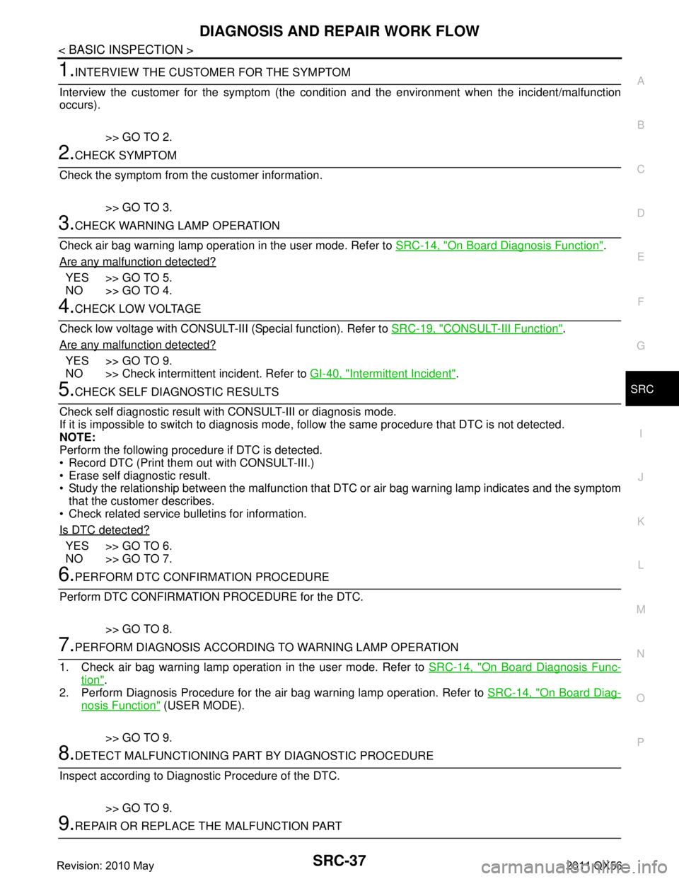
DIAGNOSIS AND REPAIR WORK FLOWSRC-37
< BASIC INSPECTION >
C
DE
F
G
I
J
K L
M A
B
SRC
N
O P
1.INTERVIEW THE CUSTOMER FOR THE SYMPTOM
Interview the customer for the symptom (the condi tion and the environment when the incident/malfunction
occurs).
>> GO TO 2.
2.CHECK SYMPTOM
Check the symptom from the customer information.
>> GO TO 3.
3.CHECK WARNING LAMP OPERATION
Check air bag warning lamp operation in the user mode. Refer to SRC-14, "
On Board Diagnosis Function".
Are any malfunction detected?
YES >> GO TO 5.
NO >> GO TO 4.
4.CHECK LOW VOLTAGE
Check low voltage with CONSULT-III (Special function). Refer to SRC-19, "
CONSULT-III Function".
Are any malfunction detected?
YES >> GO TO 9.
NO >> Check intermittent incident. Refer to GI-40, "
Intermittent Incident".
5.CHECK SELF DIAGNOSTIC RESULTS
Check self diagnostic result with CONSULT-III or diagnosis mode.
If it is impossible to switch to diagnosis mode, follow the same pr ocedure that DTC is not detected.
NOTE:
Perform the following procedure if DTC is detected.
Record DTC (Print them out with CONSULT-III.)
Erase self diagnostic result.
Study the relationship between the malfunction that DT C or air bag warning lamp indicates and the symptom
that the customer describes.
Check related service bulletins for information.
Is DTC detected?
YES >> GO TO 6.
NO >> GO TO 7.
6.PERFORM DTC CONFIRMATION PROCEDURE
Perform DTC CONFIRMATION PROCEDURE for the DTC.
>> GO TO 8.
7.PERFORM DIAGNOSIS ACCORDING TO WARNING LAMP OPERATION
1. Check air bag warning lamp operation in the user mode. Refer to SRC-14, "
On Board Diagnosis Func-
tion".
2. Perform Diagnosis Procedure for the air bag warning lamp operation. Refer to SRC-14, "
On Board Diag-
nosis Function" (USER MODE).
>> GO TO 9.
8.DETECT MALFUNCTIONING PA RT BY DIAGNOSTIC PROCEDURE
Inspect according to Diagnostic Procedure of the DTC.
>> GO TO 9.
9.REPAIR OR REPLACE THE MALFUNCTION PART
Revision: 2010 May2011 QX56