2011 INFINITI QX56 check engine
[x] Cancel search: check enginePage 3917 of 5598
![INFINITI QX56 2011 Factory Service Manual
PCS-76
< SYMPTOM DIAGNOSIS >[POWER DISTRIBUTION SYSTEM]
PUSH-BUTTON IGNITION SW
ITCH DOES NOT OPERATE
SYMPTOM DIAGNOSIS
PUSH-BUTTON IGNITION SWITCH DOES NOT OPERATE
DescriptionINFOID:0000000006220228 INFINITI QX56 2011 Factory Service Manual
PCS-76
< SYMPTOM DIAGNOSIS >[POWER DISTRIBUTION SYSTEM]
PUSH-BUTTON IGNITION SW
ITCH DOES NOT OPERATE
SYMPTOM DIAGNOSIS
PUSH-BUTTON IGNITION SWITCH DOES NOT OPERATE
DescriptionINFOID:0000000006220228](/manual-img/42/57033/w960_57033-3916.png)
PCS-76
< SYMPTOM DIAGNOSIS >[POWER DISTRIBUTION SYSTEM]
PUSH-BUTTON IGNITION SW
ITCH DOES NOT OPERATE
SYMPTOM DIAGNOSIS
PUSH-BUTTON IGNITION SWITCH DOES NOT OPERATE
DescriptionINFOID:0000000006220228
Check that vehicle is under the condition shown in “C onditions of vehicle” before starting diagnosis, and check
each symptom.
NOTE:
The engine start function, door lock function, power dist ribution system, and NATS-IVIS/NVIS in the Intelligent
Key system are closely related to each other regarding c ontrol. The vehicle security function can operate only
when the door lock and power distribution system are operating normally.
Conditions of Vehicle (Operating Conditions)
“ENGINE START BY I-KEY” in “WORK SUPPOR T” is ON when setting on CONSULT-III.
One or more of Intelligent Keys with registered Intelligent Key ID is in the vehicle.
Diagnosis ProcedureINFOID:0000000006220229
1.PERFORM WORK SUPPORT
Perform “INSIDE ANT DIAGNOSIS” on Wo rk Support of “INTELLIGENT KEY”.
Refer to DLK-41, "
INTELLIGENT KEY : CONSULT-III Function (BCM - INTELLIGENT KEY)".
>> GO TO 2.
2.PERFORM SELF-DIAGNOSIS RESULT
Perform Self-Diagnosis Result of “BCM”.
Is DTC detected?
YES >> Refer to BCS-57, "DTCIndex".
NO >> GO TO 3.
3.CHECK PUSH-BUTTON IGNITION SWITCH
Check push-button ignition switch.
Refer to PCS-71, "
ComponentFunctionCheck".
Is the operation normal?
YES >> GO TO 4.
NO >> Repair or replace malfunctioning parts.
4.CONFIRM THE OPERATION
Confirm the operation again.
Is the inspection normal?
YES >> Check intermittent incident. Refer to GI-40, "Intermittent Incident".
NO >> GO TO 1.
Revision: 2010 May2011 QX56
Page 3918 of 5598
![INFINITI QX56 2011 Factory Service Manual
PCS
PUSH-BUTTON IGNITION SWITCH POSITION INDICATOR DOES NOT ILLUMI-
NATE
PCS-77
< SYMPTOM DIAGNOSIS > [POWER DISTRIBUTION SYSTEM]
C
D
E
F
G H
I
J
K L
B A
O P
N
PUSH-BUTTON IGNITION SWITCH PO
SITION I INFINITI QX56 2011 Factory Service Manual
PCS
PUSH-BUTTON IGNITION SWITCH POSITION INDICATOR DOES NOT ILLUMI-
NATE
PCS-77
< SYMPTOM DIAGNOSIS > [POWER DISTRIBUTION SYSTEM]
C
D
E
F
G H
I
J
K L
B A
O P
N
PUSH-BUTTON IGNITION SWITCH PO
SITION I](/manual-img/42/57033/w960_57033-3917.png)
PCS
PUSH-BUTTON IGNITION SWITCH POSITION INDICATOR DOES NOT ILLUMI-
NATE
PCS-77
< SYMPTOM DIAGNOSIS > [POWER DISTRIBUTION SYSTEM]
C
D
E
F
G H
I
J
K L
B A
O P
N
PUSH-BUTTON IGNITION SWITCH PO
SITION INDICATOR DOES NOT IL-
LUMINATE
DescriptionINFOID:0000000006220230
Before performing the diagnosis in the follo wing table, check “Work Flow”. Refer to PCS-53, "Work Flow".
Check that vehicle is under the condition shown in “Conditions of vehicle” before starting diagnosis, and
check each symptom.
Conditions of Vehicle (Operating Conditions)
“ENGINE START BY I-KEY” in “WORK SUPPORT” is ON when setting on CONSULT-III.
One or more of Intelligent Keys with registered Intelligent Key ID is in the vehicle.
Diagnosis ProcedureINFOID:0000000006220231
1.CHECK PUSH-BUTTON IGNITION SWITCH INDICATOR
Check push-button ignition switch indicator.
Refer to PCS-74, "
ComponentFunctionCheck".
Is the inspection result normal?
YES >> GO TO 2.
NO >> Repair or replace the malfunctioning parts.
2.CONFIRM THE OPERATION
Confirm the operation again.
Is the result normal?
YES >> Check intermittent incident. Refer to GI-40, "Intermittent Incident".
NO >> GO TO 1.
Revision: 2010 May2011 QX56
Page 4078 of 5598

PG
BATTERY INSPECTIONPG-159
< BASIC INSPECTION >
C
DE
F
G H
I
J
K L
B A
O P
N
BASIC INSPECTION
BATTERY INSPECTION
How to Handle BatteryINFOID:0000000006288754
CAUTION:
If it becomes necessary to start the engine with
a booster battery and jumper cables, use a 12-volt
booster battery.
After connecting battery cables, ensure that they are tightly clamped to battery terminals for good
contact.
Never add distilled water through the hole used to check specific gravity.
METHODS OF PREVENTING OVER-DISCHARGE
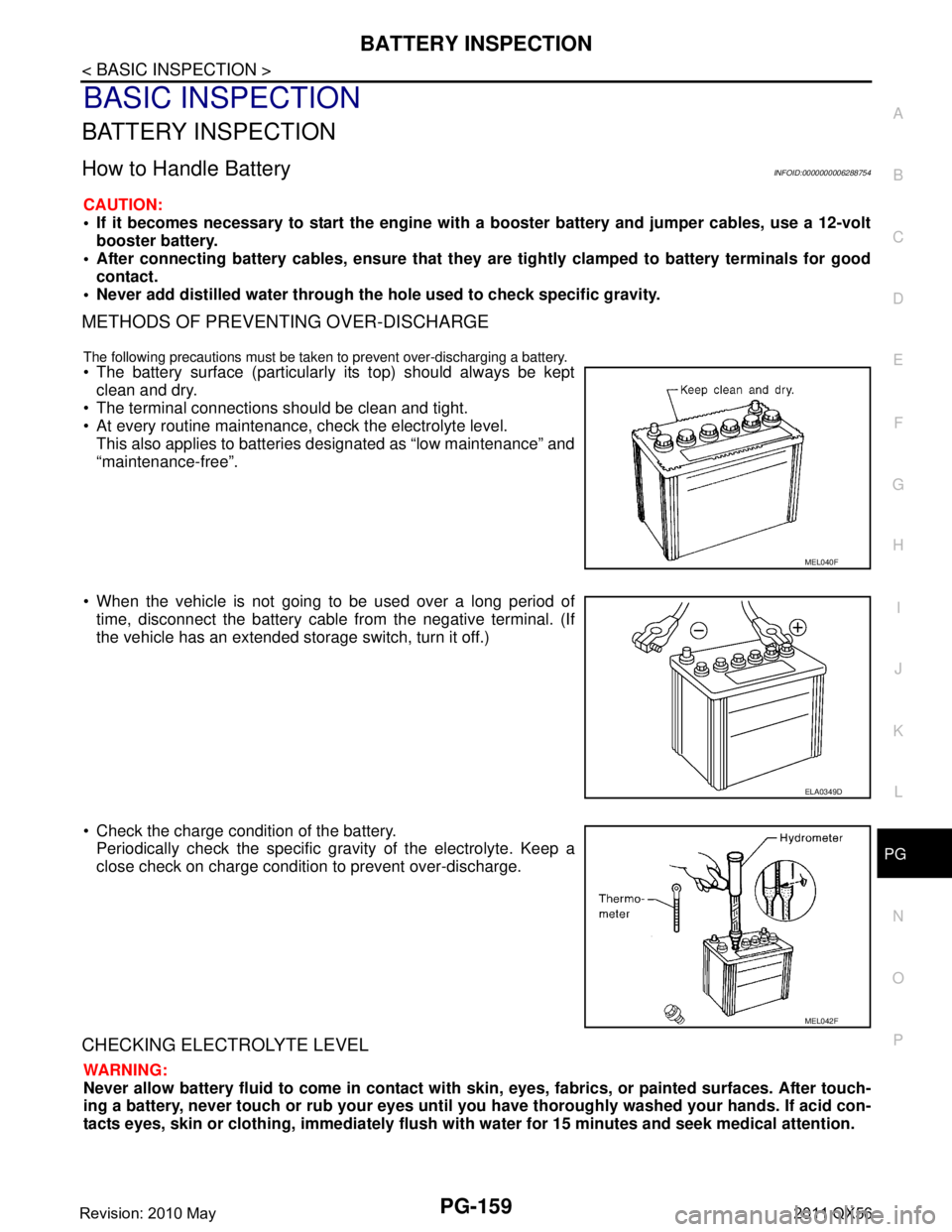
The following precautions must be taken to prevent over-discharging a battery.
The battery surface (particularly its top) should always be kept
clean and dry.
The terminal connections should be clean and tight.
At every routine maintenance, check the electrolyte level. This also applies to batteries designated as “low maintenance” and
“maintenance-free”.
When the vehicle is not going to be used over a long period of time, disconnect the battery cable from the negative terminal. (If
the vehicle has an extended storage switch, turn it off.)
Check the charge condition of the battery. Periodically check the specific gr avity of the electrolyte. Keep a
close check on charge condition to prevent over-discharge.
CHECKING ELECTROLYTE LEVEL
WARNING:
Never allow battery fluid to come in contact with skin, eyes, fabrics, or painted surfaces. After touch-
ing a battery, never touch or rub your eyes until you have thoroughly washed your hands. If acid con-
tacts eyes, skin or clothing, imme diately flush with water for 15 minutes and seek medical attention.
MEL040F
ELA0349D
MEL042F
Revision: 2010 May2011 QX56
Page 4234 of 5598

RF-20
< DTC/CIRCUIT DIAGNOSIS >
VEHICLE SPEED SIGNAL CIRCUIT
VEHICLE SPEED SIGNAL CIRCUIT
Component Function CheckINFOID:0000000006141233
1.CHECK SUNROOF MOTOR FUNCTION
Check tilt up/down & slide open/close operations with sunroof switch.
Is the inspection result normal?
YES >> GO TO 2.
NO >> Check sunroof switch. Refer to RF-21, "
DiagnosisProcedure".
2.CHECK SUNROOF MOTOR ASSEMBLY INPUT SIGNAL
1. Start engine.
2. Drive the vehicle at more than 40 km/h (25 MPH). CAUTION:
Always drive vehicle at a safe speed.
NOTE:
This procedure may be conducted with the drive wheel s lifted in the shop or by driving the vehicle.
If a road test is expected to be easier , it is unnecessary to lift the vehicle.
3. Check tilt up/down & slide open/clos e operations with sunroof switch.
Is the inspection result normal?
YES >> INSPECTION END
NO >> Refer to RF-20, "
DiagnosisProcedure".
Diagnosis ProcedureINFOID:0000000006141234
SUNROOF MOTOR ASSEMBLY
1.CHECK SUNROOF MOTOR ASSEMBLY INPUT SIGNAL
1. Turn ignition switch OFF.
2. Disconnect combination meter harness connector and sunroof motor assembly harness connector.
3. Check continuity between combination meter harness connector and sunroof motor assembly harness connector.
4. Check continuity between sunroof mo tor assembly harness connector and ground.
Is the inspection result normal?
YES >> Check combination meter. Refer to MWI-61, "DiagnosisProcedure".
NO >> Repair or replace harness or connector.
Combination meter Sunroof motor assembly Continuity
Connector Terminal Connector Terminal
M34 30 R4 8 Exists
Sunroof motor assembly GroundContinuity
Connector Terminal
R4 8 Not existed
Revision: 2010 May2011 QX56
Page 4241 of 5598

SQUEAK AND RATTLE TROUBLE DIAGNOSESRF-27
< SYMPTOM DIAGNOSIS >
C
DE
F
G H
I
J
L
M A
B
RF
N
O P
If the noise can be duplicated easily during the test drive, to help identify the source of the noise, try to dupli-
cate the noise with the vehicle stopped by doing one or all of the following items:
1) Close a door.
2) Tap or push/pull around the area where the noise appears to be coming from.
3) Rev the engine.
4) Use a floor jack to recreate vehicle “twist”.
5) At idle, apply engine load (electrical load, half-cl utch on M/T models, drive position on A/T models).
6) Raise the vehicle on a hoist and hit a tire with a rubber hammer.
Drive the vehicle and attempt to duplicate the conditions the customer states exist when the noise occurs.
If it is difficult to duplicate the noise, drive the vehicle slowly on an undulating or rough road to stress the vehicle body.
CHECK RELATED SERVICE BULLETINS
After verifying the customer concern or symptom, che ck ASIST for Technical Service Bulletins (TSBs) related
to the concern or symptom.
If a TSB relates to the symptom, follow the procedure to repair the noise.
LOCATE THE NOISE AND IDENTIFY THE ROOT CAUSE
1. Narrow down the noise to a general area. To help pinpoint the source of the noise, use a listening tool
(Chassis ear: J-39570, engine ear, and mechanics stethoscope).
2. Narrow down the noise to a more specific area and identify the cause of the noise by:
Removing the component(s) in the area that is / are suspected to be the cause of the noise.
Do not use too much force when removing clips and fasteners, otherwise clips and fasteners can be broken
or lost during the repair, resulting in the creation of new noise.
Tapping or pushing/pulling the component(s) that is / are suspected to be the cause of the noise.
Do not tap or push/pull the component(s) with excessive force, otherwise the noise is eliminated only tempo-
rarily.
Feeling for a vibration by hand by touching the component(s ) that is / are suspected to be the cause of the
noise.
Placing a piece of paper between components that are suspected to be the cause of the noise.
Looking for loose components and contact marks. Refer to RF-28, "
Inspection Procedure".
REPAIR THE CAUSE
If the cause is a loose component, tighten the component securely.
If the cause is insufficient clearance between components:
- Separate components by repositioning or loosening and retightening the components, if possible.
- Insulate components with a suitable insulator such as urethane pads, foam blocks, felt cloth tape, or ure-
thane tape. A NISSAN Squeak and Rattle Kit (J-43980) is available through the authorized NISSAN Parts
Department.
CAUTION:
Never use excessive force as many components are constructed of plastic and may be damaged.
NOTE:
Always check with the Parts Department for the latest parts information.
The following materials are contained in the NISSA N Squeak and Rattle Kit (J-43980). Each item can be
ordered separately as needed.
URETHANE PADS [1.5 mm (0.059 in) thick]
Insulates connectors, harness, etc.
76268-9E005: 100 ×135 mm (3.937 ×5.315 in)
76884-71L01: 60 ×85 mm (2.362 ×3.346 in)
76884-71L02: 15 ×25 mm (0.591 ×0.984 in)
INSULATOR (Foam blocks)
Insulates components from contact. Can be used to fill space behind a panel.
73982-9E000: 45 mm (1.772 in) thick, 50 ×50 mm (1.969 ×1.969 in)
73982-50Y00: 10 mm (0.394 in) thick, 50 ×50 mm (1.969 ×1.969 in)
INSULATOR (Light foam block)
80845-71L00: 30 mm (1.181 in) thick, 30 ×50 mm (1.181 ×1.969in)
FELT CLOTHTAPE
Used to insulate where movement does not occur. Ideal for instrument panel applications.
68370-4B000: 15 ×25 mm (0.591 ×0.984 in) pad
68239-13E00: 5 mm (0.197 in) wide tape roll
Revision: 2010 May2011 QX56
Page 4257 of 5598

RSU-2
< PRECAUTION >
PRECAUTIONS
PRECAUTION
PRECAUTIONS
Precautions for SuspensionINFOID:0000000006225656
• When installing rubber bushings, the final tightening must be carried out under unladen conditions with tires
on ground. Spilled oil might shorten the life of rubber bushings. Be sure to wipe off any spilled oil.
- Unladen conditions mean that fuel, engine coolant and l ubricant are full. Spare tire, jack, hand tools and
mats are in designated positions.
After servicing suspension parts, be sure to check wheel alignment.
Self-lock nuts are not reusable. Always use new ones when installing. Since new self-lock nuts are pre-oiled,
tighten as they are.
Revision: 2010 May2011 QX56
Page 4261 of 5598

RSU-6
< PERIODIC MAINTENANCE >
WHEEL ALIGNMENT
WHEEL ALIGNMENT
InspectionINFOID:0000000006225661
DESCRIPTION
Measure wheel alignment under unladen conditions.
NOTE:
“Unladen conditions” means that fuel, engine coolant, and lubricant are full. Spare tire, jack, hand tools and
mats are in designated positions.
PRELIMINARY CHECK
Check the following:
Tires for improper air pressure and wear
Road wheels for runout. Refer to WT-64, "
Inspection".
Wheel bearing axial end play. Refer to RAX-5, "
Inspection".
Ball joint axial end play of suspension arm and front lower link. Refer to RSU-20, "
Ball Joint".
Shock absorber operation
Each mounting point of axle and suspension for looseness and deformation
Each of front lower link, rear lower link, rear suspension member, suspension arm and shock absorber for
cracks, deformation, and other damage
Vehicle height (posture)
GENERAL INFORMATION AND RECOMMENDATIONS
A four-wheel thrust alignment should be performed.
- This type of alignment is recomm ended for any NISSAN/INFINITI vehicle.
- The four-wheel “thrust” process helps ensure that t he vehicle is properly aligned and the steering wheel is
centered.
- The alignment rack itself should be capable of accepting any NISSAN/INFINITI vehicle.
- The rack should be checked to ensure that it is level.
Make sure the machine is properly calibrated.
- Your alignment equipment should be regularly calib rated in order to give correct information.
- Check with the manufacturer of your specific equi pment for their recommended Service/Calibration Sched-
ule.
ALIGNMENT PROCESS
IMPORTANT:
Use only the alignment specifications listed in this Service Manual.
When displaying the alignment settings, many alignment machines use “indicators”: (Green/red, plus or
minus, Go/No Go). Never use these indicators.
- The alignment specifications programmed into your machine that operate these indicators may not be cor-
rect.
- This may result in an ERROR.
Some newer alignment machines are equipped with an optional “Rolling Compensation” method to “com- pensate” the sensors (alignment targets or head units). Never use this “Rolling Compensation” method.
- Use the “Jacking Compensation Method”. After installi ng the alignment targets or head units, raise the vehi-
cle and rotate the wheels 1/2 turn both ways.
- See Instructions in the alignment machine you're using for more information on this.
AdjustmentINFOID:0000000006225662
CAMBER
Revision: 2010 May2011 QX56
Page 4300 of 5598

PRECAUTIONSSBC-3
< PRECAUTION >
C
DE
F
G
I
J
K L
M A
B
SBC
N
O P
PRECAUTION
PRECAUTIONS
Precaution for Supplemental Restraint System (SRS) "AIR BAG" and "SEAT BELT
PRE-TENSIONER"
INFOID:0000000006237873
The Supplemental Restraint System such as “A IR BAG” and “SEAT BELT PRE-TENSIONER”, used along
with a front seat belt, helps to reduce the risk or severi ty of injury to the driver and front passenger for certain
types of collision. This system includes seat belt switch inputs and dual stage front air bag modules. The SRS
system uses the seat belt switches to determine the front air bag deployment, and may only deploy one front
air bag, depending on the severity of a collision and whether the front occupants are belted or unbelted.
Information necessary to service the system safely is included in the “SRS AIR BAG” and “SEAT BELT” of this
Service Manual.
WARNING:
• To avoid rendering the SRS inoper ative, which could increase the risk of personal injury or death in
the event of a collision that would result in air ba g inflation, all maintenance must be performed by
an authorized NISSAN/INFINITI dealer.
Improper maintenance, including in correct removal and installation of the SRS, can lead to personal
injury caused by unintentional act ivation of the system. For removal of Spiral Cable and Air Bag
Module, see the “SRS AIR BAG”.
Do not use electrical test equipm ent on any circuit related to the SRS unless instructed to in this
Service Manual. SRS wiring harnesses can be identi fied by yellow and/or orange harnesses or har-
ness connectors.
PRECAUTIONS WHEN USING POWER TOOLS (AIR OR ELECTRIC) AND HAMMERS
WARNING:
When working near the Air Bag Diagnosis Sensor Unit or other Air Bag System sensors with the
ignition ON or engine running, DO NOT use air or electric power tools or strike near the sensor(s)
with a hammer. Heavy vibration could activate the sensor(s) and deploy the air bag(s), possibly
causing serious injury.
When using air or electric power tools or hammers , always switch the ignition OFF, disconnect the
battery, and wait at least 3 minutes before performing any service.
Precaution for Seat Belt ServiceINFOID:0000000006237874
CAUTION:
Before removing the seat belt pre-tensioner assembly, turn the ignition switch off, disconnect the
both battery cables and wait at least 3 minutes.
Do not use electrical test equipment for seat belt pre-tensioner connector.
After replacing or reinstalling seat belt pre-tens ioner assembly, or reconnecting front seat belt pre-
tensioner connector, check the system function. Refer to SRC-11, "
System Diagram".
Do not use disassemble buckle or seat belt assembly.
Replace anchor bolts if th ey are deformed or worn out.
Never oil tongue and buckle.
If any component of seat belt assembly is questio nable, do not repair. Replace the whole seat belt
assembly.
If webbing is cut, frayed, or damaged, replace seat belt assembly.
When replacing seat belt assembly, u se a genuine NISSAN seat belt assembly.
AFTER A COLLISION
WARNING:
Inspect all seat belt assemblies including retractors and attaching hardware after any collision.
NISSAN recommends that all seat belt assemblies in u se during a collision be replaced unless the col-
lision was minor and the belts show no damage a nd continue to operate properly. Failure to do so
could result in serious personal injury in an accide nt. Seat belt assemblies not in use during a colli-
sion should also be replaced if either damage or im proper operation is noted. Seat belt pre-tensioner
should be replaced even if the seat belts are not in use during a frontal collision in which the air bags
are deployed.
Replace any seat belt assembly (including anchor bolts) if:
Revision: 2010 May2011 QX56