2011 INFINITI QX56 body int
[x] Cancel search: body intPage 1771 of 5598
BACK DOORDLK-235
< REMOVAL AND INSTALLATION >
C
DE
F
G H
I
J
L
M A
B
DLK
N
O P
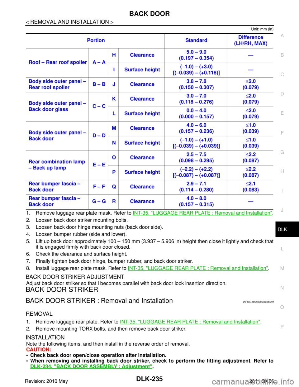
Unit: mm (in)
1. Remove luggage rear plate mask. Refer to INT-35, "LUGGAGE REAR PLATE : Removal and Installation".
2. Loosen back door striker mounting bolts.
3. Loosen back door hinge mounting nuts (back door side).
4. Loosen bumper rubber (side and lower).
5. Lift up back door approximately 100 – 150 mm (3.937 – 5.906 in) height then close it lightly and check that
it is engaged firmly with back door closed.
6. Check the clearance and surface height.
7. Finally tighten back door hinge, bumper rubber, and back door striker.
8. Install luggage rear plate mask. Refer to INT-35, "
LUGGAGE REAR PLATE : Removal and Installation".
BACK DOOR STRIKER ADJUSTMENT
Adjust back door striker so that i becomes parallel with back door lock insertion direction.
BACK DOOR STRIKER
BACK DOOR STRIKER : Removal and InstallationINFOID:0000000006226089
REMOVAL
1. Remove luggage rear plate. Refer to INT-35, "LUGGAGE REAR PLATE : Removal and Installation".
2. Remove mounting TORX bolts, and then remove back door striker.
INSTALLATION
Note the following items, and then install in the reverse order of removal.
CAUTION:
Check back door open/close ope ration after installation.
When removing and installing b ack door striker, check to perform th e fitting adjustment. Refer to
DLK-234, "
BACK DOOR ASSEMBLY : Adjustment".
Portion Standard
Difference
(LH/RH, MAX)
Roof – Rear roof spoiler A – A H Clearance
5.0 – 9.0
(0.197 – 0.354) —
I Surface height (
− 1.0) – (+3.0)
[( −0.039) – (+0.118)] —
Body side outer panel –
Rear roof spoiler B – B J Clearance 3.8 – 7.8
(0.150 – 0.307) ≤
2.0
(0.079)
Body side outer panel –
Back door glass C – CK Clearance
3.0 – 7.0
(0.118 – 0.276) ≤
2.0
(0.079)
L Surface height 0.0 – 4.0
(0.000 – 0.157) ≤
2.0
(0.079)
Body side outer panel –
Back door D – DM Clearance
4.0 – 6.0
(0.157 – 0.236) ≤
1.0
(0.039)
N Surface height (
− 1.0) – (+1.0)
[( −0.039) – (+0.039)] ≤
1.0
(0.039)
Rear combination lamp
– Back up lamp E – EO Clearance
2.5 – 7.5
(0.098 – 0.295) ≤
2.2
(0.087)
P Surface height (
− 2.2) – (+2.2)
[( −0.087) – (+0.087)] ≤
2.2
(0.087)
Rear bumper fascia –
Back door F – F Q Clearance 2.9 – 7.1
(0.114 – 0.280) ≤
2.1
(0.083)
Rear bumper fascia –
Back door G – G R Clearance 4.0 – 8.0
(0.157 – 0.315) —
Revision: 2010 May2011 QX56
Page 1772 of 5598
DLK-236
< REMOVAL AND INSTALLATION >
BACK DOOR
BACK DOOR HINGE
BACK DOOR HINGE : Removal and InstallationINFOID:0000000006226090
CAUTION:
Operate with two workers, because of its heavy weight.
Use protective tape or cloth to protect fr om damage during remove and installation.
REMOVAL
1. Remove back door assembly. Refer to DLK-232, "BACK DOOR ASSEMBLY : Removal and Installation".
2. Remove back door hinge mounting nuts (body side), and then remove back door hinge.
INSTALLATION
Note the following items, and then install in the reverse order of removal.
CAUTION:
Apply anticorrosive agent onto the mounting surface.
Check back door open/close op eration after installation.
Check back door hinge ro tating part for poor lubricatio n. If necessary, apply body grease.
When removing and installing back door assembly, perform the fitting adjustment. Refer to DLK-234,
"BACK DOOR ASSEMBLY : Adjustment".
After installation, apply touch-up paint (the body color) onto the head of back door hinge mounting
nuts.
BACK DOOR STAY
BACK DOOR STAY : Removal and InstallationINFOID:0000000006226091
REMOVAL
1. Support back door lock with the proper material to prevent it from falling.
WARNING:
Body injury may occur if no su pporting rod is holding the back door op en when removing the
back door stay.
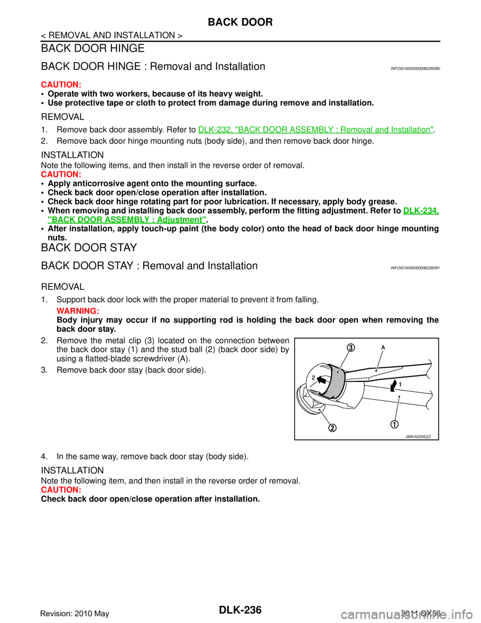
2. Remove the metal clip (3) located on the connection between the back door stay (1) and the stud ball (2) (back door side) by
using a flatted-blade screwdriver (A).
3. Remove back door stay (back door side).
4. In the same way, remove back door stay (body side).
INSTALLATION
Note the following item, and then install in the reverse order of removal.
CAUTION:
Check back door open/close ope ration after installation.
JMKIA2255ZZ
Revision: 2010 May2011 QX56
Page 1773 of 5598
BACK DOORDLK-237
< REMOVAL AND INSTALLATION >
C
DE
F
G H
I
J
L
M A
B
DLK
N
O P
BACK DOOR STAY : Disposal INFOID:0000000006226092
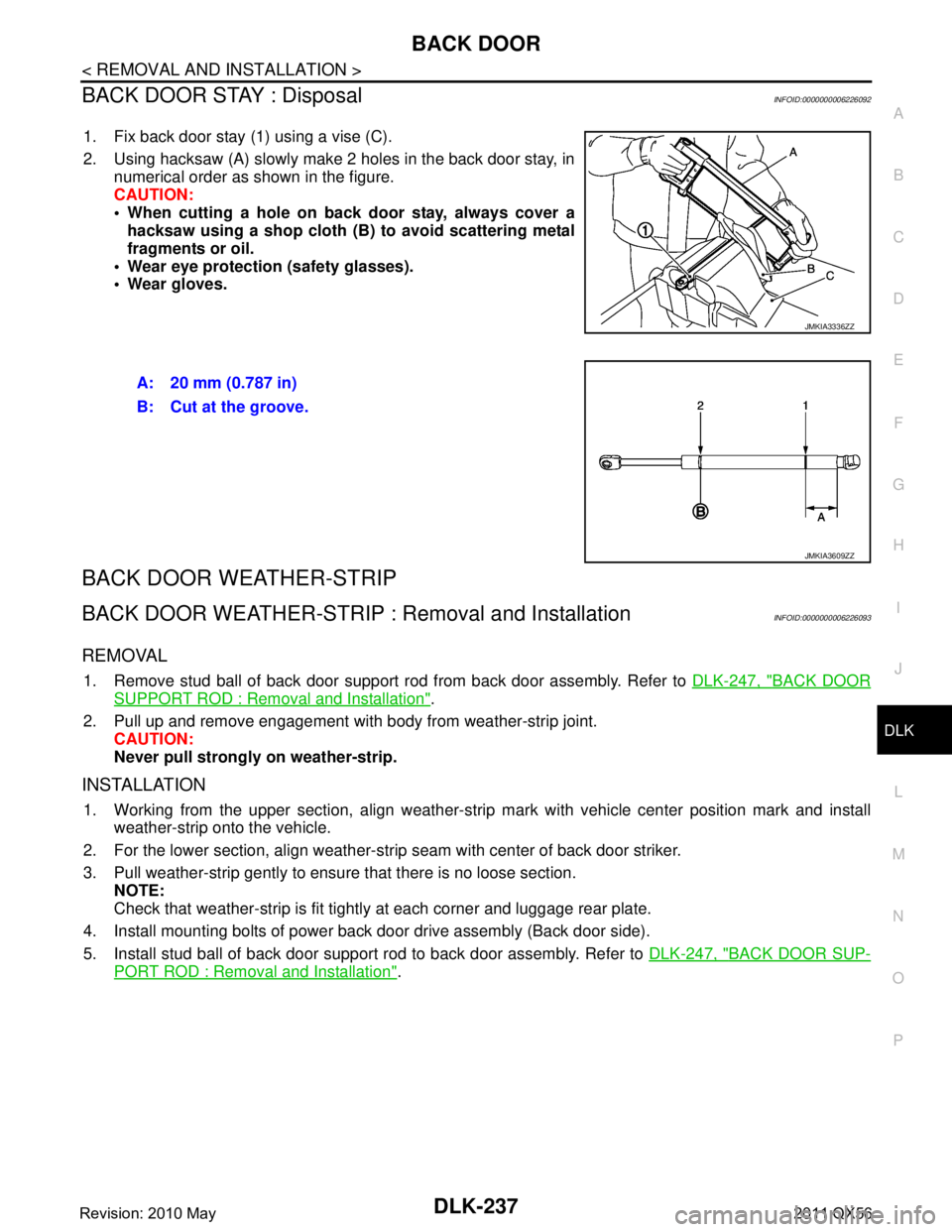
1. Fix back door stay (1) using a vise (C).
2. Using hacksaw (A) slowly make 2 holes in the back door stay, in numerical order as shown in the figure.
CAUTION:
When cutting a hole on back door stay, always cover ahacksaw using a shop cloth (B) to avoid scattering metal
fragments or oil.
Wear eye protection (safety glasses).
Wear gloves.
BACK DOOR WEATHER-STRIP
BACK DOOR WEATHER-STRIP : Removal and InstallationINFOID:0000000006226093
REMOVAL
1. Remove stud ball of back door support rod from back door assembly. Refer to DLK-247, "BACK DOOR
SUPPORT ROD : Removal and Installation".
2. Pull up and remove engagement with body from weather-strip joint. CAUTION:
Never pull strongly on weather-strip.
INSTALLATION
1. Working from the upper section, align weather-strip mark with vehicle center position mark and install
weather-strip onto the vehicle.
2. For the lower section, align weather-str ip seam with center of back door striker.
3. Pull weather-strip gently to ensure that there is no loose section. NOTE:
Check that weather-strip is fit tightly at each corner and luggage rear plate.
4. Install mounting bolts of power back door drive assembly (Back door side).
5. Install stud ball of back door support rod to back door assembly. Refer to DLK-247, "
BACK DOOR SUP-
PORT ROD : Removal and Installation".
JMKIA3336ZZ
A: 20 mm (0.787 in)
B: Cut at the groove.
JMKIA3609ZZ
Revision: 2010 May2011 QX56
Page 1785 of 5598
FUEL FILLER LID OPENERDLK-249
< REMOVAL AND INSTALLATION >
C
DE
F
G H
I
J
L
M A
B
DLK
N
O P
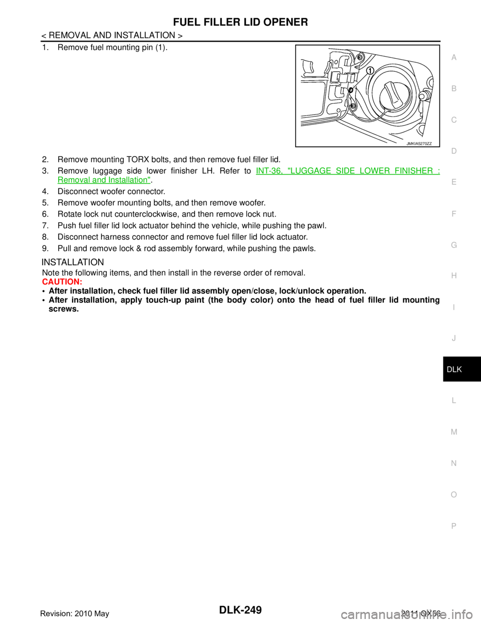
1. Remove fuel mounting pin (1).
2. Remove mounting TORX bolts, and then remove fuel filler lid.
3. Remove luggage side lower finisher LH. Refer to INT-36, "
LUGGAGE SIDE LOWER FINISHER :
Removal and Installation".
4. Disconnect woofer connector.
5. Remove woofer mounting bolts, and then remove woofer.
6. Rotate lock nut counterclockwise, and then remove lock nut.
7. Push fuel filler lid lock actuator behind the vehicle, while pushing the pawl.
8. Disconnect harness connector and remove fuel filler lid lock actuator.
9. Pull and remove lock & rod assembly forward, while pushing the pawls.
INSTALLATION
Note the following items, and then install in the reverse order of removal.
CAUTION:
After installation, check fuel filler li d assembly open/close, lock/unlock operation.
After installation, apply touch-up paint (the body color) onto the head of fuel filler lid mounting
screws.
JMKIA5270ZZ
Revision: 2010 May2011 QX56
Page 1787 of 5598
CAB MOUNTING INSULATORDLK-251
< REMOVAL AND INSTALLATION >
C
DE
F
G H
I
J
L
M A
B
DLK
N
O P
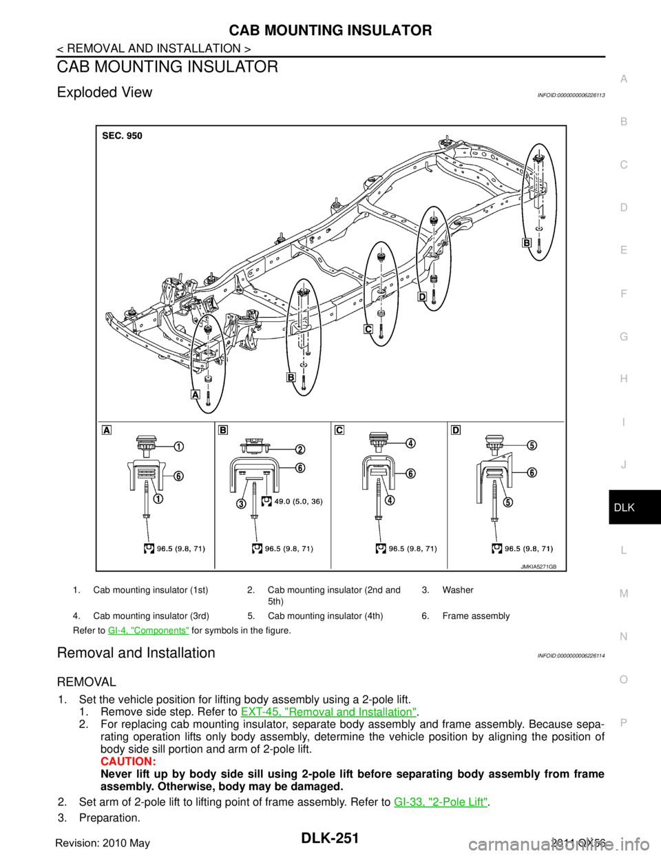
CAB MOUNTING INSULATOR
Exploded ViewINFOID:0000000006226113
Removal and InstallationINFOID:0000000006226114
REMOVAL
1. Set the vehicle position for lifting body assembly using a 2-pole lift. 1. Remove side step. Refer to EXT-45, "
Removal and Installation".
2. For replacing cab mounting insulator, separate body assembly and frame assembly. Because sepa-
rating operation lifts only body assembly, determine the vehicle position by aligning the position of
body side sill portion and arm of 2-pole lift.
CAUTION:
Never lift up by body side sill using 2-pole lift before separating body assembly from frame
assembly. Otherwise, body may be damaged.
2. Set arm of 2-pole lift to lifting point of frame assembly. Refer to GI-33, "
2-Pole Lift".
3. Preparation.
1. Cab mounting insulator (1st) 2. Cab mounting insulator (2nd and 5th)3. Washer
4. Cab mounting insulator (3rd) 5. Cab mo unting insulator (4th) 6. Frame assembly
Refer to GI-4, "
Components" for symbols in the figure.
JMKIA5271GB
Revision: 2010 May2011 QX56
Page 1789 of 5598
CAB MOUNTING INSULATORDLK-253
< REMOVAL AND INSTALLATION >
C
DE
F
G H
I
J
L
M A
B
DLK
N
O P
Remove brake tube from connector (front wheel well LH and RH side). Refer to BR-22, "FRONT :
Exploded View"
Vehicle center side
Remove A/T control cable from manual lever. Refer to TM-178, "
Removal and Installation".
Separate parking brake rear cable (LH and RH) from parking brake front cable. Refer to PB-5, "
Removal
and Installation".
Remove engine room harness connector (frame assembly RH center side). Refer to PG-146, "
Engine
Room Harness"
- Remove harness connector protector.
- Disconnect chassis harness connector from engine room harness connector.
- Remove harness bracket bolt, and then remove engi ne room harness connector from frame assembly.
Vehicle rear side
Remove EVAP hose (canister side).
Remove rear final drive breather hose from air breather tube (body side). Refer to DLN-201, "
Removal
and Installation".
Disconnect body harness connector from chassis harness connectors (frame assembly LH rear side).
Refer to PG-150, "
Body Harness"
6. Set safety stand to frame assembly. Release arm of 2-pole lift.
7. Remove cab mounting insulator bolts.
8. Set arm of 2-pole lift to body side sill portion of body.
9. Slowly lift 2-pole lift.
CAUTION:
Check that there is no inte rference with the vehicle.
Check that all connection points are disconnected.
10. Remove cab mounting insulator.
INSTALLATION
Note the following items, and then install in the reverse order of removal.
CAUTION:
Before starting engine, check oil/fl uid levels including engine coolant and engine oil. If levels are
less than the required quantity, fill to the specified level. Refer to MA-10, "
Fluids and Lubricants".
Warm up engine thoroughly to check that there is no leakage of fuel, exhaust gases, or any oil/fluids
including engine oil and engine coolant.
Revision: 2010 May2011 QX56
Page 2387 of 5598
![INFINITI QX56 2011 Factory Service Manual
P050E COLD START CONTROLEC-363
< DTC/CIRCUIT DIAGNOSIS > [VK56VD]
C
D
E
F
G H
I
J
K L
M A
EC
NP
O
Perform
EC-148, "Work Procedure".
Is Idle Air Volume Learning carried out successfully?
YES >> GO TO INFINITI QX56 2011 Factory Service Manual
P050E COLD START CONTROLEC-363
< DTC/CIRCUIT DIAGNOSIS > [VK56VD]
C
D
E
F
G H
I
J
K L
M A
EC
NP
O
Perform
EC-148, "Work Procedure".
Is Idle Air Volume Learning carried out successfully?
YES >> GO TO](/manual-img/42/57033/w960_57033-2386.png)
P050E COLD START CONTROLEC-363
< DTC/CIRCUIT DIAGNOSIS > [VK56VD]
C
D
E
F
G H
I
J
K L
M A
EC
NP
O
Perform
EC-148, "Work Procedure".
Is Idle Air Volume Learning carried out successfully?
YES >> GO TO 2.
NO >> Follow the instruction of Idle Air Volume Learning.
2.CHECK INTAKE SYSTEM
Check for the cause of intake air volume lacking. Refer to the following.
Crushed intake air passage
Intake air passage clogging
Clogging of throttle body
Is the inspection result normal?
YES >> GO TO 3.
NO >> Repair or replace malfunctioning part
3.CHECK FUEL INJECTION SYSTEM FUNCTION
Perform DTC Confirmation Procedure for DTC P0171, P0174. Refer to EC-263, "
DTC Logic".
Is the inspection result normal?
YES >> GO TO 4.
NO >> Proceed to EC-264, "
Diagnosis Procedure" for DTC P0171, P0174.
4.PERFORM DTC CONFIRMATION PROCEDURE
1. Turn ignition switch ON.
2. Erase DTC.
3. Perform DTC Confirmation Procedure. See EC-362, "
DTC Logic".
Is the 1st trip DTC P050E displayed again?
YES >> GO TO 5.
NO >> INSPECTION END
5.REPLACE ECM
Replace ECM. Refer to EC-535, "
Removal and Installation".
>> INSPECTION END
Revision: 2010 May2011 QX56
Page 2451 of 5598
![INFINITI QX56 2011 Factory Service Manual
P1554 BATTERY CURRENT SENSOREC-427
< DTC/CIRCUIT DIAGNOSIS > [VK56VD]
C
D
E
F
G H
I
J
K L
M A
EC
NP
O
1. Check the continuity between battery current
sensor harness connector and ECM harness connect INFINITI QX56 2011 Factory Service Manual
P1554 BATTERY CURRENT SENSOREC-427
< DTC/CIRCUIT DIAGNOSIS > [VK56VD]
C
D
E
F
G H
I
J
K L
M A
EC
NP
O
1. Check the continuity between battery current
sensor harness connector and ECM harness connect](/manual-img/42/57033/w960_57033-2450.png)
P1554 BATTERY CURRENT SENSOREC-427
< DTC/CIRCUIT DIAGNOSIS > [VK56VD]
C
D
E
F
G H
I
J
K L
M A
EC
NP
O
1. Check the continuity between battery current
sensor harness connector and ECM harness connector.
2. Also check harness for short to ground and short to power.
Is the inspection result normal?
YES >> GO TO 12.
NO >> GO TO 11.
11 .DETECT MALFUNCTIONING PART
Check the following.
Harness for open or short between battery current sensor and ECM
Loose or poor connection for each connector and harness
>> Repair open circuit, short to ground or short to power in harness or connectors.
12.CHECK BATTERY CURRENT SENSOR
Refer to EC-427, "
Component Inspection (Battery Current Sensor)".
Is the inspection result normal?
YES >> GO TO 13.
NO >> Replace battery negative cable assembly.
13.CHECK INTERMITTENT INCIDENT
Refer to GI-40, "
Intermittent Incident".
>> INSPECTION END
Component Inspection (B attery Current Sensor)INFOID:0000000006217931
1.CHECK BATTERY CURRENT SENSOR
1. Turn ignition switch OFF.
2. Reconnect harness connectors disconnected.
3. Disconnect battery negative cable.
4. Install jumper cable between battery negative terminal and body ground.
5. Turn ignition switch ON.
6. Check the voltage between ECM harness connector terminals under the following conditions.
Before measuring the terminal voltage, confirm that the battery is fully charged. Refer to PG-159, "How to Handle Battery".
Is the inspection result normal?
YES >> INSPECTION END
NO >> Replace battery negative cable assembly.
Battery current sensor ECM
Continuity
Connector Terminal Connector Terminal
E63 3 E80 138 Existed
: To body ground
ECM Voltage (V)
Connector +–
Te r m i n a l Te r m i n a l
E80 138
(Battery current sensor signal) 150 Approx. 2.5
JPBIA3287ZZ
Revision: 2010 May2011 QX56