2011 INFINITI QX56 body int
[x] Cancel search: body intPage 2626 of 5598

EM-64
< REMOVAL AND INSTALLATION >
TIMING CHAIN
24. Remove oil pump and oil pump drive spacer.
25. Remove front oil seal from front cover using suitable tool. Use screwdriver for removal.
CAUTION:
Be careful not to damage front cover.
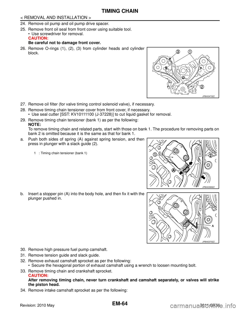
26. Remove O-rings (1), (2), (3) from cylinder heads and cylinder block.
27. Remove oil filter (for valve timing control solenoid valve), if necessary.
28. Remove timing chain tensioner cover from front cover, if necessary. Use seal cutter [SST: KV10111100 (J-37228)] to cut liquid gasket for removal.
29. Remove timing chain tensioner (bank 1) as per the following: NOTE:
To remove timing chain and related parts, start with those on bank 1. The procedure for removing parts on
bank 2 is omitted because it is the same as that for bank 1.
a. Push both sides of spring (A) against spring tension, and then press in plunger with a slack guide (2).
b. Insert a stopper pin (A) into the body hole, and then fix it with the
plunger pushed in.
30. Remove high pressure fuel pump camshaft.
31. Remove tension guide and slack guide.
32. Remove exhaust camshaft sprocket as per the following: Secure the hexagonal portion of exhaust camshaf t using a wrench to loosen mounting bolt.
33. Remove timing chain and crankshaft sprocket. CAUTION:
After removing timing chain, never turn cranksh aft and camshaft separately, or valves will strike
the piston head.
34. Remove intake camshaft sprocket as per the following:
JPBIA3473ZZ
1 : Timing chain tensioner (bank 1)
JPBIA2369ZZ
JPBIA2370ZZ
Revision: 2010 May2011 QX56
Page 2663 of 5598

ENGINE ASSEMBLYEM-101
< UNIT REMOVAL AND INSTALLATION >
C
DE
F
G H
I
J
K L
M A
EM
NP
O
5. Remove A/T assembly. Refer to
TM-205, "2WD : Exploded View" (2WD models) or TM-208, "4WD :
Exploded View" (4WD models).
6. Remove steering gear assembly. Refer to ST-41, "
Exploded View".
7. Remove front final drive assembly. Refer to DLN-162, "
Exploded View".
8. Remove exhaust manifold. Refer to EM-40, "
Exploded View".
9. Remove alternator. Refer to CHG-25, "
Exploded View".
Engine Room LH
1. Remove air cleaner and air duct. Refer to EM-27, "Exploded View".
2. Remove A/C compressor. Refer to HA-30, "
Exploded View".
3. Disconnect fuel feed hose and EVAP hose. Refer to EM-43, "
Exploded View".
CAUTION:
Fit plugs onto disconnected hoses to prevent fuel leakage.
Engine Room RH
1. Remove power steering oil pump and reservoir tank. Refer to ST-48, "Exploded View".
2. Disconnect heater hose at heater core side, and fit a plug onto hose end to prevent engine coolant leak-
age.
3. Disconnect ground cable.
4. Disconnect all clips and connectors of the engine harness from vehicle side.
Removal Work
1. Install alternator bracket. Refer to CHG-25, "Exploded View".
Temporarily tighten mounting bolts.
2. Remove intake manifold. Refer to EM-30, "
Exploded View".
3. Remove starter motor. Refer to STR-17, "
Exploded View".
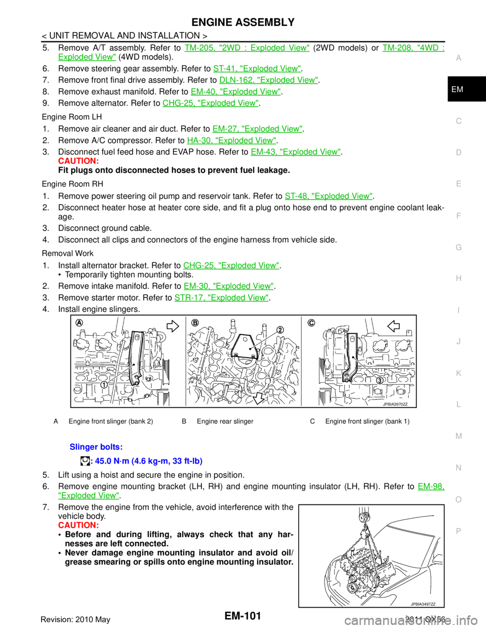
4. Install engine slingers.
5. Lift using a hoist and secure the engine in position.
6. Remove engine mounting bracket (LH, RH) and engine mounting insulator (LH, RH). Refer to EM-98,
"Exploded View".
7. Remove the engine from the vehi cle, avoid interference with the
vehicle body.
CAUTION:
Before and during lifting, always check that any har-
nesses are left connected.
Never damage engine mounti ng insulator and avoid oil/
grease smearing or spills onto engine mounting insulator.
A Engine front slinger (bank 2) B Engine rear slinger C Engine front slinger (bank 1)
Slinger bolts:
: 45.0 N·m (4.6 kg-m, 33 ft-lb)
JPBIA3970ZZ
JPBIA3497ZZ
Revision: 2010 May2011 QX56
Page 2713 of 5598

EXL-3
C
DE
F
G H
I
J
K
M A
B
EXL
N
O P
EXTERIOR LAMP FUSE ................................ ....85
Diagnosis Procedure ........................................... ....85
HEADLAMP (HI) CIRCUIT .................................86
Component Function Check ................................ ....86
Diagnosis Procedure ...............................................86
HEADLAMP (LO) CIRCUIT ................................88
Component Function Check ................................ ....88
Diagnosis Procedure ...............................................88
XENON HEADLAMP ..........................................90
Diagnosis Procedure ........................................... ....90
HEADLAMP LEVELIZER CIRCUIT ...................91
Component Function Check ................................ ....91
Diagnosis Procedure ...............................................91
HEADLAMP AIMING SYSTEM (MANUAL) .......93
Component Inspection ........................................ ....93
FRONT FOG LAMP CIRCUIT ............................94
Component Function Check ................................ ....94
Diagnosis Procedure ...............................................94
PARKING LAMP CIRCUIT ............................. ....96
Component Function Check ................................ ....96
Diagnosis Procedure ...............................................96
FRONT SIDE MARKER LAMP CIRCUIT ...........98
Component Function Check ................................ ....98
Diagnosis Procedure ...............................................98
TURN SIGNAL LAMP CIRCUIT .........................99
Component Function Check ................................ ....99
Diagnosis Procedure ...............................................99
OPTICAL SENSOR ..........................................102
Component Function Check ................................ ..102
Diagnosis Procedure .............................................102
HAZARD SWITCH .......................................... ..105
Component Function Check ................................ ..105
Diagnosis Procedure .............................................105
AFS SWITCH ....................................................107
Component Function Check ................................ ..107
Diagnosis Procedure .............................................107
Component Inspection ..........................................108
TAIL LAMP CIRCUIT .......................................109
BODY SIDE ........................................................... ..109
BODY SIDE : Component Function Check ...........109
BODY SIDE : Diagnosis Procedure ......................109
BACK DOOR SIDE ................................................ ..110
BACK DOOR SIDE : Component Function Check ..110
BACK DOOR SIDE : Diagnosis Procedure ...........111
LICENSE PLATE LAMP CIRCUIT ...................112
Component Function Check ................................ ..112
Diagnosis Procedure .............................................112
SYMPTOM DIAGNOSIS ............................113
EXTERIOR LIGHTING SYSTEM SYMPTOMS .113
Symptom Table ................................................... ..113
NORMAL OPERATING CONDITION .............116
Description .............................................................116
BOTH SIDE HEADLAMPS DO NOT SWITCH
TO HIGH BEAM ..............................................
117
Description .............................................................117
Diagnosis Procedure .............................................117
BOTH SIDE HEADLAMPS (LO) ARE NOT
TURNED ON ...................................................
118
Description ........................................................... ..118
Diagnosis Procedure .............................................118
PARKING, LICENSE PLATE, SIDE MARKER
AND TAIL LAMPS ARE NOT TURNED ON ...
119
Description .............................................................119
Diagnosis Procedure .............................................119
BOTH SIDE FRONT FOG LAMPS ARE NOT
TURNED ON ...................................................
120
Description ........................................................... ..120
Diagnosis Procedure .............................................120
PERIODIC MAINTENANCE ......................121
HEADLAMP AIMING ADJUSTMENT .............121
description ........................................................... ..121
Aiming Adjustment Procedure ...............................122
FRONT FOG LAMP AIMING ADJUSTMENT .123
Description .............................................................123
Aiming Adjustment Procedure ...............................123
REMOVAL AND INSTALLATION .............125
FRONT COMBINATION LAMP ......................125
Exploded View ..................................................... ..125
Removal and Installation .......................................125
Replacement .........................................................126
Disassembly and Assembly ...................................127
FRONT FOG LAMP ........................................128
Exploded View .......................................................128
Removal and Installation .......................................128
Replacement .........................................................128
SIDE TURN SIGNAL LAMP ............................130
Exploded View .......................................................130
Removal and Installation .......................................130
OPTICAL SENSOR .........................................131
Exploded View .......................................................131
Removal and Installation .......................................131
LIGHTING & TURN SIGNAL SWITCH ...........132
Exploded View .......................................................132
Revision: 2010 May2011 QX56
Page 2717 of 5598
![INFINITI QX56 2011 Factory Service Manual
COMPONENT PARTSEXL-7
< SYSTEM DESCRIPTION > [XENON TYPE]
C
D
E
F
G H
I
J
K
M A
B
EXL
N
O P
*1: With headlamp aiming control system (manual) models
*2: With AFS system models
EXTERIOR LIGHTING SYSTEM INFINITI QX56 2011 Factory Service Manual
COMPONENT PARTSEXL-7
< SYSTEM DESCRIPTION > [XENON TYPE]
C
D
E
F
G H
I
J
K
M A
B
EXL
N
O P
*1: With headlamp aiming control system (manual) models
*2: With AFS system models
EXTERIOR LIGHTING SYSTEM](/manual-img/42/57033/w960_57033-2716.png)
COMPONENT PARTSEXL-7
< SYSTEM DESCRIPTION > [XENON TYPE]
C
D
E
F
G H
I
J
K
M A
B
EXL
N
O P
*1: With headlamp aiming control system (manual) models
*2: With AFS system models
EXTERIOR LIGHTING SYSTEM : Component DescriptionINFOID:0000000006213888
1. Combination meter 2. BCM
Refer to BCS-4, "
BODY CONTROL
SYSTEM : Compon ent Parts Loca-
tion"
3. Optical sensor
4. IPDM E/R Refer to PCS-4, "
Component Parts
Location"
5. ECM
Refer to EC-16, "
Component Parts
Location"
6. Parking lamp
7. Front turn signal lamp 8. Front fog lamp 9. Headlamp
10. Front side marker lamp 11. Combination switch 12. Headlamp aiming switch*
1
13. Front door switch (driver side) 14.
Steering angle sensor*2
Refer to BRC-10, "Component Parts
Location"
15. License plate lamp
16. Tail lamp 17. Rear turn signal lamp 18. Rear side marker lamp
19. Hazard switch 20. Side turn signal lamp 21. Headlamp swivel actuator
22. Headlamp aiming motor 23. AFS switch*
224.Rear height sensor*2
25.AFS control unit*226.Front height sensor*2
A. Front combination lamp (back) B. View with instrument driver lower
panel (LH)C. Rear suspension member (RH)
D. View with instrument lower cover E. Front suspension arm (RH)
Part Description
BCM Controls the exterior lighting system.
ECM*
1Transmits engine speed signal to AFS control unit. (via CAN communication)
TCM*
1Transmits Shift position signal to AFS control unit. (via CAN communication)
IPDM E/R Controls the integrated relay, and supplies voltage to the load according to the request
from BCM (via CAN communication).
AFS control unit*
1AFS control unit judges the vehicle condition from each signal. AFS control unit con-
trols AFS function and the headlamp aiming.
Combination meter Outputs the vehicle speed signal (8-pulse) to AFS control unit.
Blinks the turn signal indicator lamp and outputs the turn signal operating sound with
integrated buzzer according to the request from BCM (via CAN communication).
Turns the tail lamp indicator lamp and high beam indicator lamp ON according to the
request from BCM (via CAN communication).
Turns the AFS OFF indicator lamp ON/OFF /blinking according to the request from
AFS control unit (via CAN communication).
Headlamp assembly Xenon bulb Refer to
EXL-8, "
FRONT COMBINATION LAMP : Xenon Headlamp".
HID control unit Refer to EXL-9, "
FRONT COMBINATION LAMP : HID control unit".
High beam solenoid Refer to EXL-9, "
FRONT COMBINATION LAMP : High Beam Solenoid".
Aiming motor Refer to EXL-9, "
FRONT COMBINATION LAMP : Aiming Motor".
Swivel actuator*
1Refer to EXL-9, "FRONT COMBINATION LAMP : Swivel Actuator".
Height sensor*
1
The height sensor is installed to the front suspension member and rear suspension member.
The height sensor detects the suspension arm displacement as the vehicle height change.
The height sensor transmits the height sensor signal to AFS control unit.
NOTE:
The sensor angle of the unloaded vehicle position is the reference value.
Optical sensor Optical sensor converts the outside brightness (lux) to voltage and transmits the opti-
cal sensor signal to BCM.
Revision: 2010 May2011 QX56
Page 2732 of 5598
![INFINITI QX56 2011 Factory Service Manual
EXL-22
< SYSTEM DESCRIPTION >[XENON TYPE]
DIAGNOSIS SYSTEM (BCM)
DIAGNOSIS SYSTEM (BCM)
COMMON ITEM
COMMON ITEM : CONSULT-III Fu
nction (BCM - COMMON ITEM)INFOID:0000000006368037
APPLICATION ITEM
CON INFINITI QX56 2011 Factory Service Manual
EXL-22
< SYSTEM DESCRIPTION >[XENON TYPE]
DIAGNOSIS SYSTEM (BCM)
DIAGNOSIS SYSTEM (BCM)
COMMON ITEM
COMMON ITEM : CONSULT-III Fu
nction (BCM - COMMON ITEM)INFOID:0000000006368037
APPLICATION ITEM
CON](/manual-img/42/57033/w960_57033-2731.png)
EXL-22
< SYSTEM DESCRIPTION >[XENON TYPE]
DIAGNOSIS SYSTEM (BCM)
DIAGNOSIS SYSTEM (BCM)
COMMON ITEM
COMMON ITEM : CONSULT-III Fu
nction (BCM - COMMON ITEM)INFOID:0000000006368037
APPLICATION ITEM
CONSULT-III performs the following functions via CAN communication with BCM.
SYSTEM APPLICATION
BCM can perform the following functions for each system.
NOTE:
It can perform the diagnosis modes except the following for all sub system selection items.
×: Applicable item
*: This item is indicated, but not used.
FREEZE FRAME DATA (FFD)
The BCM records the following vehicle condition at the time a particular DTC is detected, and displays on
CONSULT-III.
Diagnosis mode Function Description
Work Support Changes the setting for each system function.
Self Diagnostic Result Displays the diagnosis results judged by BCM. Refer to BCS-57, "
DTCIndex".
CAN Diag Support Monitor Monitors the reception status of CAN communication viewed from BCM. Refer to CONSULT-III opera-
tion manual.
Data Monitor The BCM input/output signals are displayed.
Active Test The signals used to activate ea ch device are forcibly supplied from BCM.
Ecu Identification The BCM part number is displayed.
Configuration Read and save the vehicle specification.
Write the vehicle specification when replacing BCM.
System Sub system selection item Diagnosis mode
Work Support Data Monitor Active Test
Door lock DOOR LOCK ×××
Rear window defogger REAR DEFOGGER ××
Warning chime BUZZER ××
Interior room lamp timer INT LAMP ×××
Exterior lamp HEAD LAMP ×××
Wiper and washer WIPER ×××
Turn signal and hazard warning lamps FLASHER ×××
— AIR CONDITONER* ××
Intelligent Key system
Engine start system INTELLIGENT KEY
×××
Combination switch COMB SW ×
Body control system BCM ×
IVIS IMMU ×××
Interior room lamp battery saver BATTERY SAVER ×××
Back door TRUNK ×
Vehicle security system THEFT ALM ×××
RAP system RETAINED PWR ×
Signal buffer system SIGNAL BUFFER ××
Revision: 2010 May2011 QX56
Page 2831 of 5598
![INFINITI QX56 2011 Factory Service Manual
HEADLAMP AIMING ADJUSTMENTEXL-121
< PERIODIC MAINTENANCE > [XENON TYPE]
C
D
E
F
G H
I
J
K
M A
B
EXL
N
O P
PERIODIC MAINTENANCE
HEADLAMP AIMING ADJUSTMENT
descriptionINFOID:0000000006213990
preparatio INFINITI QX56 2011 Factory Service Manual
HEADLAMP AIMING ADJUSTMENTEXL-121
< PERIODIC MAINTENANCE > [XENON TYPE]
C
D
E
F
G H
I
J
K
M A
B
EXL
N
O P
PERIODIC MAINTENANCE
HEADLAMP AIMING ADJUSTMENT
descriptionINFOID:0000000006213990
preparatio](/manual-img/42/57033/w960_57033-2830.png)
HEADLAMP AIMING ADJUSTMENTEXL-121
< PERIODIC MAINTENANCE > [XENON TYPE]
C
D
E
F
G H
I
J
K
M A
B
EXL
N
O P
PERIODIC MAINTENANCE
HEADLAMP AIMING ADJUSTMENT
descriptionINFOID:0000000006213990
preparation before adjusting
NOTE:
for details, refer to the regulations in your own country.
perform aiming if the vehicle front body has been repaired and/or the headlamp assembly has been
replaced.
before performing aiming adjustment, check the following. adjust the tire pressure to the specification.
fill with fuel, engine coolant and each oil.
maintain the unloaded vehicle condition. (remove luggage from the passenger compartment and the lug- gage room.)
NOTE:
do not remove the temporary tire, jack and on-vehicle tool.
wipe out dirt on the headlamp.
CAUTION:
never use organic solvent (thinner, gasoline etc.)
ride alone on the driver seat.
aiming adjustment screw
JMLIA1319ZZ
A. Headlamp RH HI /LO (UP/DOWN)
adjustment screw B. Headlamp LH HI/LO (UP/DOWN)
adjustment screw
: Vehicle center
Revision: 2010 May2011 QX56
Page 2833 of 5598
![INFINITI QX56 2011 Factory Service Manual
FRONT FOG LAMP AIMING ADJUSTMENTEXL-123
< PERIODIC MAINTENANCE > [XENON TYPE]
C
D
E
F
G H
I
J
K
M A
B
EXL
N
O P
FRONT FOG LAMP AI MING ADJUSTMENT
DescriptionINFOID:0000000006213992
PREPARATION BEFORE INFINITI QX56 2011 Factory Service Manual
FRONT FOG LAMP AIMING ADJUSTMENTEXL-123
< PERIODIC MAINTENANCE > [XENON TYPE]
C
D
E
F
G H
I
J
K
M A
B
EXL
N
O P
FRONT FOG LAMP AI MING ADJUSTMENT
DescriptionINFOID:0000000006213992
PREPARATION BEFORE](/manual-img/42/57033/w960_57033-2832.png)
FRONT FOG LAMP AIMING ADJUSTMENTEXL-123
< PERIODIC MAINTENANCE > [XENON TYPE]
C
D
E
F
G H
I
J
K
M A
B
EXL
N
O P
FRONT FOG LAMP AI MING ADJUSTMENT
DescriptionINFOID:0000000006213992
PREPARATION BEFORE ADJUSTING
NOTE:
For details, refer to the regulations in your own country.
Perform aiming if the vehicle front body has been repaired and/or the headlamp assembly has been
replaced.
Before performing aiming adjustm ent, check the following. Adjust the tire pressure to the specification.
Fill with fuel, engine coolant and each oil.
Maintain the unloaded vehicle condition. (Remove luggage from the passenger compartment and the trunk
room.)
NOTE:
Do not remove the temporary tire, jack and on-vehicle tool.
Wipe out dirt on the headlamp. CAUTION:
Never use organic solvent (thinner, gasoline etc.)
Ride alone on the driver seat.
AIMING ADJUSTMENT SCREW
Turn the aiming adjusting screw for adjustment.
For the position and direction of the adjusting screw, refer to the figure.
NOTE:
A screwdriver or hexagonal wrench [6 mm (0.24 in)] can be used
for adjustment.
Aiming Adjustment ProcedureINFOID:0000000006213993
1. Place the screen. NOTE:
Stop the vehicle facing the wall.
Place the board on a plain road vertically.
2. Face the vehicle with the screen. Maintain 10 m (32.8 ft) between the front fog lamp center and the
screen.
3. Start the engine. Turn the front fog lamp ON. NOTE:
Shut off the headlamp light with the board to pr event from illuminating the adjustment screen.
CAUTION:
Never cover the lens surface with a tape etc. The lens is made of resin.
4. Adjust the cutoff line height (A) with the aiming adjus tment screw so that the distance (X) between the hor-
izontal center line of front fog lamp (H) and (A) becomes 200 mm (7.87 in).
A: UP
B: DOWN
JPLIA0915ZZ
Revision: 2010 May2011 QX56
Page 2856 of 5598

EXT-1
BODY EXTERIOR, DOORS, ROOF & VEHICLE SECURITY
C
D
E
F
G H
I
J
L
M
SECTION EXT
A
B
EXT
N
O P
CONTENTS
EXTERIOR
PRECAUTION ................ ...............................3
PRECAUTIONS .............................................. .....3
Precaution for Supplemental Restraint System
(SRS) "AIR BAG" and "SEAT BELT PRE-TEN-
SIONER" ............................................................. ......
3
Precaution Necessary for Steering Wheel Rota-
tion after Battery Disconnect .....................................
3
Precaution for Procedure without Cowl Top Cover ......4
Precaution for Work ..................................................4
PREPARATION ............................................5
PREPARATION .............................................. .....5
Commercial Service Tools ................................. ......5
SYMPTOM DIAGNOSIS ...............................6
SQUEAK AND RATTLE TROUBLE DIAG-
NOSES ........................ ........................................
6
Work Flow ........................................................... ......6
Inspection Procedure ................................................8
Diagnostic Worksheet .............................................10
REMOVAL AND INSTALLATION ...............12
FRONT BUMPER ........................................... ....12
Exploded View .................................................... ....12
Removal and Installation .........................................13
REAR BUMPER .................................................16
Exploded View .................................................... ....16
Removal and Installation .........................................17
FRONT GRILLE .................................................19
Exploded View .................................................... ....19
Removal and Installation .........................................19
COWL TOP .........................................................21
Exploded View .................................................... ....21
Removal and Installation .........................................21
FENDER PROTECTOR ......................................23
FENDER PROTECTOR ......................................... ....23
FENDER PROTECTOR : Exploded View ...............23
FENDER PROTECTOR : Removal and Installa-
tion ...........................................................................
23
REAR WHEEL HOUSE PROTECTOR .................. ....23
REAR WHEEL HOUSE PROTECTOR : Exploded
View .........................................................................
24
REAR WHEEL HOUSE PROTECTOR : Removal
and Installation ........................................................
24
FLOOR SIDE FAIRING .....................................25
Exploded View .........................................................25
Removal and Installation .........................................25
OVER FENDER .................................................26
Exploded View .........................................................26
Removal and Installation .........................................26
ROOF RAIL .......................................................29
Exploded View .........................................................29
Removal and Installation .........................................29
ROOF SIDE MOLDING .....................................31
Exploded View .........................................................31
Removal and Installation .........................................31
DOOR OUTSIDE MOLDING .............................32
Exploded View .........................................................32
Removal and Installation .........................................32
DOOR PARTING SEAL ....................................34
Exploded View .........................................................34
Removal and Installation .........................................34
SILL MOLDING .................................................36
Exploded View .........................................................36
Removal and Installation .........................................36
DOOR SASH COVER .......................................37
Exploded View .........................................................37
Removal and Installation .........................................37
Revision: 2010 May2011 QX56