2011 INFINITI QX56 oil
[x] Cancel search: oilPage 5040 of 5598
![INFINITI QX56 2011 Factory Service Manual
POWER STEERING OIL PUMPST-53
< REMOVAL AND INSTALLATION >
C
DE
F
H I
J
K L
M A
B
ST
N
O P
1. Connect the oil pressure gauge [SST: KV48103500 (J-26357)] and the oil pressure gauge adapter [SST: KV4810 INFINITI QX56 2011 Factory Service Manual
POWER STEERING OIL PUMPST-53
< REMOVAL AND INSTALLATION >
C
DE
F
H I
J
K L
M A
B
ST
N
O P
1. Connect the oil pressure gauge [SST: KV48103500 (J-26357)] and the oil pressure gauge adapter [SST: KV4810](/manual-img/42/57033/w960_57033-5039.png)
POWER STEERING OIL PUMPST-53
< REMOVAL AND INSTALLATION >
C
DE
F
H I
J
K L
M A
B
ST
N
O P
1. Connect the oil pressure gauge [SST: KV48103500 (J-26357)] and the oil pressure gauge adapter [SST: KV48102500 (J-
33914)] between oil pump discharge connector and high-pres-
sure hose. Bleed air from the hydraulic circuit while opening
valve fully. Refer to ST-30, "
Inspection".
2. Start engine. Run engine until oil temperature reaches 50 to 80°C (122 to 176 °F).
CAUTION:
Leave the valve of the oil pressure gauge fully open while
starting and running engine. If engine is started with the
valve closed, the hydraulic pressure in oil pump goes up
to the relief pressure along with unusual increase of oil
temperature.
Be sure to keep hose clear of belts and other parts when engine is started.
3. Fully close the oil pressure gauge valve with engine at idle and measure the relief oil pressure.
CAUTION:
Never keep valve closed for 10 seconds or longer.
4. Open the valve slowly after measuring. Repair oil pump if the relief oil pressure is outside the standard. Refer to ST-50, "
Disassembly and Assembly".
5. Disconnect the oil pressure gauge from hydraulic circuit.
6. When installing eye bolt (1) and copper washer (2) to oil pump (3), refer to the figure.
CAUTION:
Never reuse copper washers.
Apply power steering fluid to around copper washer, theninstall eye bolt.
Install eye bolt with eye join t (assembled to high pressure
hose) (B) protrusion (A) facing with pump side cutout, and
then tighten it to the specifi ed torque after tightening by
hand. Refer to ST-54, "
Exploded View".
Securely insert harness connector to pressure sensor.
7. Check fluid level, fluid leakage and air bleeding hydraulic sys- tem after the installation. Refer to ST-30, "
Inspection".
Relief oil pressure : Refer to
ST-58, "
Relief Oil Pres-
sure".
SGIA1225E
JSGIA0452ZZ
Revision: 2010 May2011 QX56
Page 5041 of 5598
ST-54
< REMOVAL AND INSTALLATION >
HYDRAULIC LINE
HYDRAULIC LINE
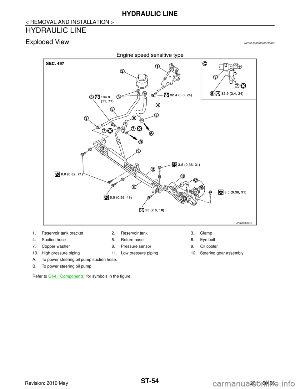
Exploded ViewINFOID:0000000006225615
Engine speed sensitive type
JPGIA0096GB
1. Reservoir tank bracket 2. Reservoir tank 3. Clamp
4. Suction hose 5. Return hose 6. Eye bolt
7. Copper washer 8. Pressure sensor 9. Oil cooler
10. High pressure piping 11. Low pressure piping 12. Steering gear assembly
A. To power steering oil pump suction hose.
B. To power steering oil pump.
Refer to GI-4, "
Components" for symbols in the figure.
Revision: 2010 May2011 QX56
Page 5042 of 5598
HYDRAULIC LINEST-55
< REMOVAL AND INSTALLATION >
C
DE
F
H I
J
K L
M A
B
ST
N
O P
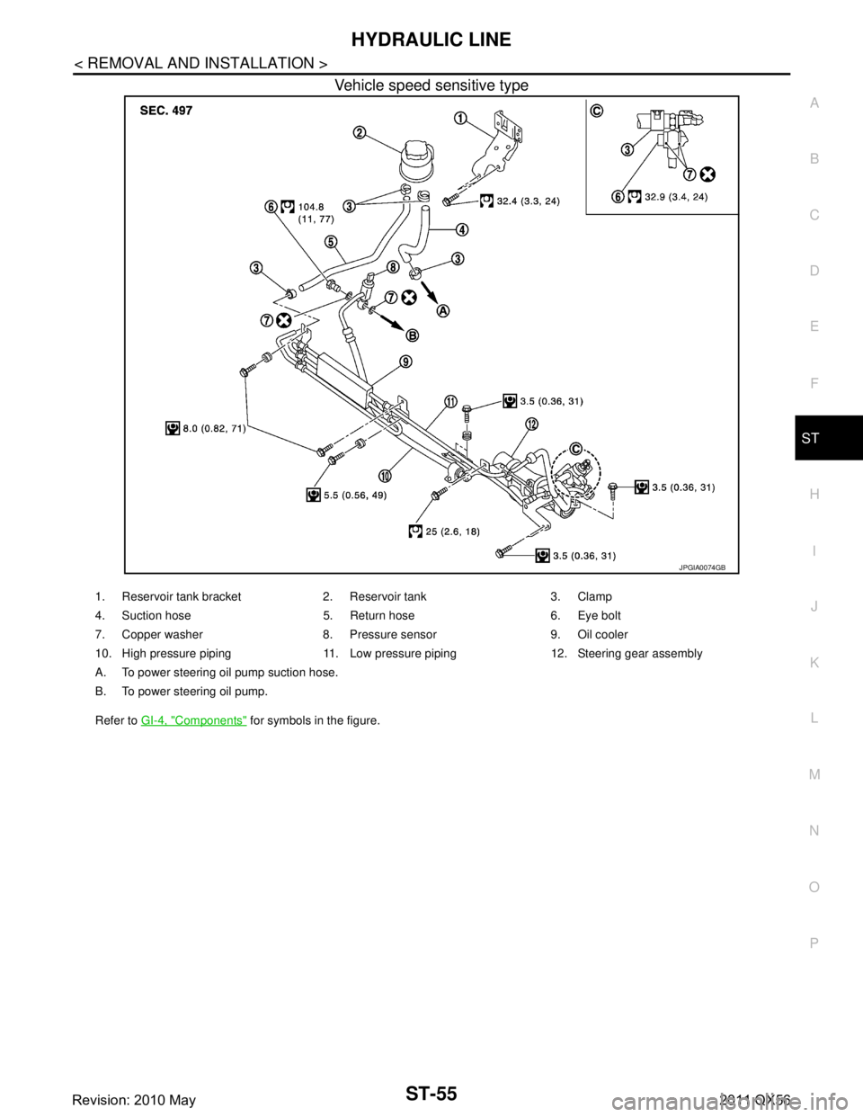
Vehicle speed sensitive type
JPGIA0074GB
1. Reservoir tank bracket 2. Reservoir tank 3. Clamp
4. Suction hose 5. Return hose 6. Eye bolt
7. Copper washer 8. Pressure sensor 9. Oil cooler
10. High pressure piping 11. Low pressure piping 12. Steering gear assembly
A. To power steering oil pump suction hose.
B. To power steering oil pump.
Refer to GI-4, "
Components" for symbols in the figure.
Revision: 2010 May2011 QX56
Page 5045 of 5598

ST-58
< SERVICE DATA AND SPECIFICATIONS (SDS)
SERVICE DATA AND SPECIFICATIONS (SDS)
Steering Shaft Sliding Range
INFOID:0000000006225625
Unit: mm (in)
Rack Sliding ForceINFOID:0000000006225626
Unit: N (kg, lb)
Rack StrokeINFOID:0000000006225627
Unit: mm (in)
Socket Swing Force and Rotating TorqueINFOID:0000000006225628
SWING FORCE
Unit: N (kg, lb)
ROTATING TORQUE
Unit: N·m (kg-m, in-lb)
Socket Axial End PlayINFOID:0000000006225629
Unit: mm (in)
Inner Socket LengthINFOID:0000000006225630
Unit: mm (in)
Relief Oil PressureINFOID:0000000006225631
Unit: kPa (bar, kg/cm2, psi)
Item Standard
Sliding range 47 (1.85)
Steering shaft length (extended position) 393 (15.47) or less
Steering shaft runout 1.5 (0.059) or less
Item Standard
Rack sliding force 249.6 – 308.4 (25.5 – 31.4, 56.2 – 69.3)
Item Standard
Rack neutral position, dimension 83.5 (3.287)
Item Spring balance
Outer socket 10.0 – 36.7 (1.02 – 3.74, 2.25 – 8.25)
Inner socket 19.4 – 32.3 (1.98 – 3.29, 4.37 – 7.26)
Item Standard
Outer socket 0.3 – 2.9 (0.03 – 0.3, 2.7 – 26)
Item Standard
Outer socket 0.5 (0.02) or less
Inner socket 0.2 (0.008) or less
Item Standard
Rack neutral position, dimension 110.8 (4.36)
Item Standard
Relief oil pressure 9,500 – 10,300 (95 – 103, 96.9 – 105.1, 1,378 – 1,494)
Revision: 2010 May2011 QX56
Page 5049 of 5598
STC-4
< SYSTEM DESCRIPTION >
COMPONENT PARTS
SYSTEM DESCRIPTION
COMPONENT PARTS
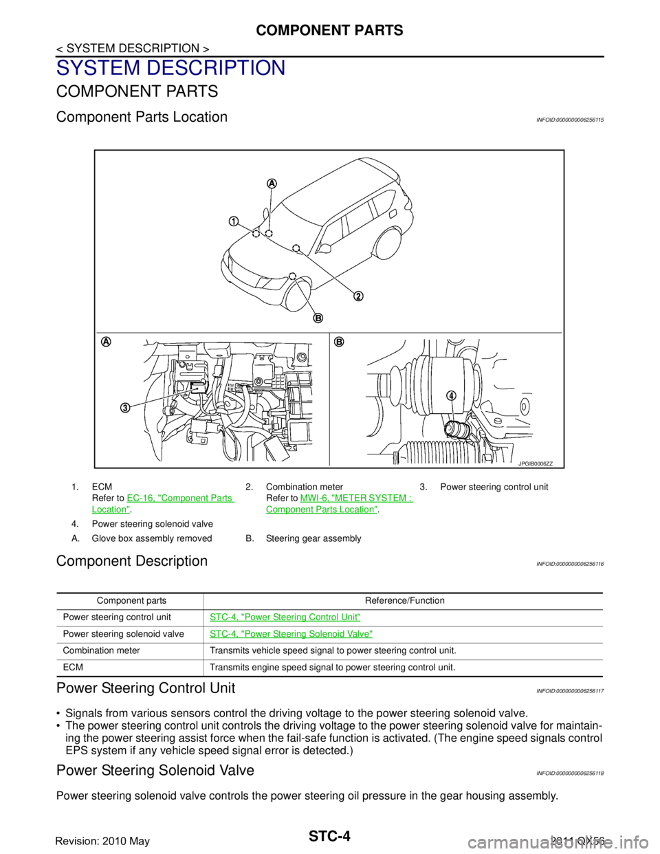
Component Parts LocationINFOID:0000000006256115
Component DescriptionINFOID:0000000006256116
Power Steering Control UnitINFOID:0000000006256117
Signals from various sensors control the driving voltage to the power steering solenoid valve.
The power steering control unit controls the driving vo ltage to the power steering solenoid valve for maintain-
ing the power steering assist force when the fail-safe function is activated. (The engine speed signals control
EPS system if any vehicle s peed signal error is detected.)
Power Steering Solenoid ValveINFOID:0000000006256118
Power steering solenoid valve controls the power steering oil pressure in the gear housing assembly.
1. ECM
Refer to EC-16, "
Component Parts
Location". 2. Combination meter
Refer to MWI-6, "
METER SYSTEM :
Component Parts Location". 3. Power steering control unit
4. Power steering solenoid valve
A. Glove box assembly removed B. Steering gear assembly
JPGIB0006ZZ
Component parts Reference/Function
Power steering control unit STC-4, "
Power Steering Control Unit"
Power steering solenoid valveSTC-4, "Power Steering Solenoid Valve"
Combination meter Transmits vehicle speed signal to power steering control unit.
ECM Transmits engine speed signal to power steering control unit.
Revision: 2010 May2011 QX56
Page 5051 of 5598
STC-6
< SYSTEM DESCRIPTION >
SYSTEM
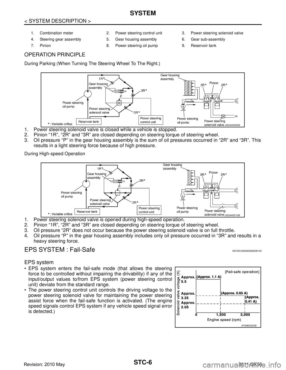
OPERATION PRINCIPLE
During Parking (When Turning The Steering Wheel To The Right.)
1. Power steering solenoid valve is closed while a vehicle is stopped.
2. Pinion “1R”, “2R” and “3R” are closed depending on steering torque of steering wheel.
3. Oil pressure “P” in the gear housing assembly is the sum of oil pressures occurred in “2R” and “3R”. Thisresults in a light steering force because of high pressure.
During High-speed Operation
1. Power steering solenoid valve is opened during high-speed operation.
2. Pinion “1R”, “2R” and “3R” are closed depending on steering torque of steering wheel.
3. Oil pressure “2R” does not occur because the pow er steering solenoid valve is on full throttle.
4. Oil pressure “P” in the gear housing assembly includes only oil pressure occurred in “3R” and results in a heavy steering force.
EPS SYSTEM : Fail-Safe INFOID:0000000006256120
EPS system
EPS system enters the fail-safe mode (that allows the steering
force to be controlled without impairi ng the drivability) if any of the
input/output values to/from EPS system (power steering control
unit) deviate from the standard range.
The power steering control unit controls the driving voltage to the
power steering solenoid valve for maintaining the power steering
assist force when the fail-safe function is activated. (The engine
speed signals control EPS system if any vehicle speed signal error
is detected.)
1. Combination meter 2. Power steering control unit 3. Power steering solenoid valve
4. Steering gear assembly 5. Gear housing assembly 6. Gear sub-assembly
7. Pinion 8. Power steering oil pump 9. Reservoir tank
JSGIA0020GB
JSGIA0021GB
JPGIB0022GB
Revision: 2010 May2011 QX56
Page 5058 of 5598
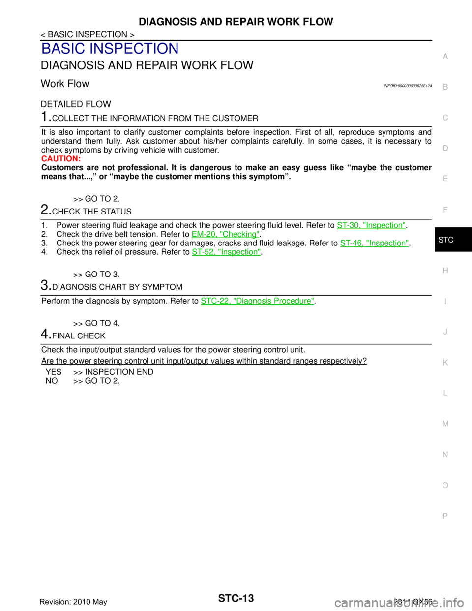
DIAGNOSIS AND REPAIR WORK FLOWSTC-13
< BASIC INSPECTION >
C
DE
F
H I
J
K L
M A
B
STC
N
O P
BASIC INSPECTION
DIAGNOSIS AND REPAIR WORK FLOW
Work FlowINFOID:0000000006256124
DETAILED FLOW
1.COLLECT THE INFORMATION FROM THE CUSTOMER
It is also important to clarify customer complaints before inspection. First of all, reproduce symptoms and
understand them fully. Ask customer about his/her complaints carefully. In some cases, it is necessary to
check symptoms by driving vehicle with customer.
CAUTION:
Customers are not professional. It is danger ous to make an easy guess like “maybe the customer
means that...,” or “maybe the cu stomer mentions this symptom”.
>> GO TO 2.
2.CHECK THE STATUS
1. Power steering fluid leakage and check the power steering fluid level. Refer to ST-30, "
Inspection".
2. Check the drive belt tension. Refer to EM-20, "
Checking".
3. Check the power steering gear for damages, cracks and fluid leakage. Refer to ST-46, "
Inspection".
4. Check the relief oil pressure. Refer to ST-52, "
Inspection".
>> GO TO 3.
3.DIAGNOSIS CHART BY SYMPTOM
Perform the diagnosis by symptom. Refer to STC-22, "
Diagnosis Procedure".
>> GO TO 4.
4.FINAL CHECK
Check the input/output standard values for the power steering control unit.
Are the power steering control unit input/output values within standard ranges respectively?
YES >> INSPECTION END
NO >> GO TO 2.
Revision: 2010 May2011 QX56
Page 5092 of 5598

TM-4
Component Inspection (Shift Lock Solenoid) ........159
SELECTOR LEVER POSITION INDICATOR ..161
Component Function Check ................................ ..161
Diagnosis Procedure .............................................161
Component Inspection (Selector Lever Position
Indicator) ................................................................
163
SYMPTOM DIAGNOSIS ............................165
SYSTEM SYMPTOM ...................................... .165
Symptom Table ................................................... ..165
PERIODIC MAINTENANCE ..................... ..175
A/T FLUID ....................................................... .175
Inspection ............................................................ ..175
REMOVAL AND INSTALLATION ..............176
A/T SHIFT SELECTOR ................................... .176
Exploded View ..................................................... ..176
Removal and Installation .......................................176
Inspection and Adjustment ....................................177
CONTROL CABLE ..........................................178
Exploded View ..................................................... ..178
Removal and Installation .......................................178
Inspection and Adjustment ....................................179
SELECTOR LEVER POSITION INDICATOR ..180
Removal and Installation ..................................... ..180
TOW MODE SWITCH ......................................181
Removal and Installation ..................................... ..181
CONTROL VALVE & TCM ..............................182
Exploded View ..................................................... ..182
Removal and Installation .......................................182
Inspection and Adjustment ....................................186
PARKING COMPONENTS ..............................187
2WD ........................................................................ ..187
2WD : Exploded View ............................................187
2WD : Removal and Installation ............................187
2WD : Inspection ...................................................190
REAR OIL SEAL ..............................................192
2WD ........................................................................ ..192
2WD : Exploded View ............................................192
2WD : Removal and Installation ............................192
2WD : Inspection ...................................................193
4WD ........................................................................ ..193
4WD : Exploded View ............................................193
4WD : Removal and Installation ............................193
4WD : Inspection and Adjustment .........................194
OUTPUT SPEED SENSOR .............................195
2WD ........................................................................ ..195
2WD : Exploded View ...........................................195
2WD : Removal and Installation ............................195
2WD : Inspection and Adjustment .........................198
AIR BREATHER HOSE ....................................199
2WD ........................................................................ .199
2WD : Exploded View ...........................................199
2WD : Removal and Installation ............................199
4WD ........................................................................ .200
4WD : Exploded View ...........................................200
4WD : Removal and Installation ............................200
FLUID COOLER SYSTEM ...............................202
Exploded View ..................................................... .202
Removal and Installation .......................................202
Inspection and Adjustment ....................................204
UNIT REMOVAL AND INSTALLATION ...205
TRANSMISSION ASSEMBLY ..........................205
2WD ........................................................................ .205
2WD : Exploded View ...........................................205
2WD : Removal and Installation ............................205
2WD : Inspection and Adjustment .........................207
4WD ........................................................................ .207
4WD : Exploded View ...........................................208
4WD : Removal and Installation ............................208
4WD : Inspection and Adjustment .........................210
UNIT DISASSEMBLY AND ASSEMBLY ..211
TRANSMISSION ASSEMBLY ..........................211
Exploded View ..................................................... .211
Oil Channel ...........................................................222
Location of Needle Bearings and Bearing Races .222
Location of Snap Rings .........................................225
Disassembly ..........................................................226
Assembly ..............................................................243
Inspection ..............................................................267
OIL PUMP, 2346 BRAKE, FRONT BRAKE
PISTON .............................................................
270
Exploded View ..................................................... .270
Disassembly ..........................................................270
Assembly ..............................................................274
Inspection and Adjustment ....................................277
UNDER DRIVE CARRIER, FRONT BRAKE
HUB ..................................................................
279
Exploded View ..................................................... .279
Disassembly ..........................................................279
Assembly ..............................................................280
Inspection ..............................................................280
FRONT CARRIER, INPUT CLUTCH, REAR
INTERNAL GEAR .............................................
282
Exploded View ..................................................... .282
Disassembly ..........................................................283
Revision: 2010 May2011 QX56