2011 INFINITI QX56 oil
[x] Cancel search: oilPage 4781 of 5598
SR-18
< REMOVAL AND INSTALLATION >
FRONT PASSENGER AIR BAG MODULE
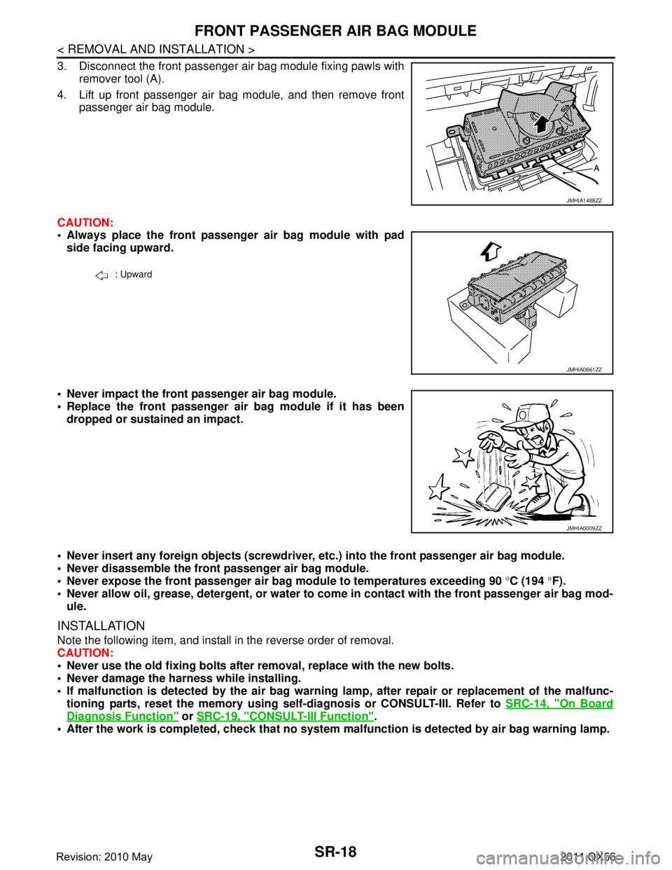
3. Disconnect the front passenger air bag module fixing pawls withremover tool (A).
4. Lift up front passenger air bag module, and then remove front passenger air bag module.
CAUTION:
Always place the front passenger air bag module with pad side facing upward.
Never impact the front passenger air bag module.
Replace the front passenger air bag module if it has been dropped or sustained an impact.
Never insert any foreign objects (screwdriver, etc.) into the front passenger air bag module.
Never disassemble the front passenger air bag module.
Never expose the front passenger air bag module to temperatures exceeding 90 °C (194 °F).
Never allow oil, grease, detergent, or water to co me in contact with the front passenger air bag mod-
ule.
INSTALLATION
Note the following item, and install in the reverse order of removal.
CAUTION:
Never use the old fixing bolts afte r removal, replace with the new bolts.
Never damage the harness while installing.
If malfunction is detected by the air bag warnin g lamp, after repair or replacement of the malfunc-
tioning parts, reset the memory using sel f-diagnosis or CONSULT-III. Refer to SRC-14, "
On Board
Diagnosis Function" or SRC-19, "CONSULT-III Function".
After the work is completed, check that no system malfunction is detected by air bag warning lamp.
JMHIA1488ZZ
: Upward
JMHIA0661ZZ
JMHIA0009ZZ
Revision: 2010 May2011 QX56
Page 4783 of 5598
SR-20
< REMOVAL AND INSTALLATION >
SIDE CURTAIN AIR BAG MODULE
For installing/removing the side curtain air bag moduleharness connector, insert thin screwdriver wrapped in
tape into notch, lift lock and remove the connector.
Install the connector with lock raised, and push lock into
the connector.
After installing the conn ector, check that the lock is
pushed securely into it.
3. Remove the side curtain air bag module fixing bolts, and then remove the side curtain air bag module.
CAUTION:
Never impact the side curtain air bag module.
Replace the side curtain air bag module if it has been dropped
or sustained an impact.
Never insert any foreign objects (screwdriver, etc.) into the side curtain air bag module.
Never disassemble the side curtain air bag module.
Never expose the side curtain air ba g module to temperatures exceeding 90 °C (194 °F).
Never allow oil, grease, detergent, or water to come in contact with the side curtain air bag module.
INSTALLATION
Note the following item, and install in the reverse order of removal.
CAUTION:
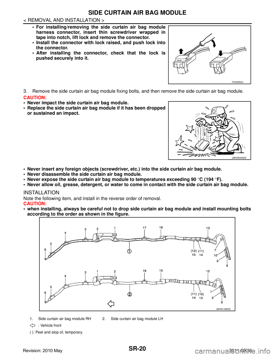
when installing, always be careful not to drop side curtain air bag module and install mounting bolts
according to the order as shown in the figure.
PHIA0953J
JMHIA0009ZZ
1. Side curtain air bag module RH 2. Side curtain air bag module LH
: Vehicle front
( ): Peel and stop of, temporary.
JMHIA1489ZZ
Revision: 2010 May2011 QX56
Page 4799 of 5598
SRC-6
< PRECAUTION >
PRECAUTIONS
PRECAUTION
PRECAUTIONS
Precaution for Supplemental Restraint System (SRS) "AIR BAG" and "SEAT BELT
PRE-TENSIONER"
INFOID:0000000006219946
The Supplemental Restraint System such as “A IR BAG” and “SEAT BELT PRE-TENSIONER”, used along
with a front seat belt, helps to reduce the risk or severi ty of injury to the driver and front passenger for certain
types of collision. This system includes seat belt switch inputs and dual stage front air bag modules. The SRS
system uses the seat belt switches to determine the front air bag deployment, and may only deploy one front
air bag, depending on the severity of a collision and w hether the front occupants are belted or unbelted.
Information necessary to service the system safely is included in the “SRS AIR BAG” and “SEAT BELT” of this
Service Manual.
WARNING:
• To avoid rendering the SRS inopera tive, which could increase the risk of personal injury or death in
the event of a collision that would result in air bag inflation, all maintenance must be performed by
an authorized NISS AN/INFINITI dealer.
Improper maintenance, including in correct removal and installation of the SRS, can lead to personal
injury caused by unintent ional activation of the system. For re moval of Spiral Cable and Air Bag
Module, see the “SRS AIR BAG”.
Do not use electrical test equipmen t on any circuit related to the SRS unless instructed to in this
Service Manual. SRS wiring harnesses can be identi fied by yellow and/or orange harnesses or har-
ness connectors.
PRECAUTIONS WHEN USING POWER TOOLS (AIR OR ELECTRIC) AND HAMMERS
WARNING:
When working near the Air Bag Diagnosis Sensor Unit or other Air Bag System sensors with the ignition ON or engine running, DO NOT use air or electric power tools or strike near the sensor(s)
with a hammer. Heavy vibration could activate the sensor(s) and deploy the air bag(s), possibly
causing serious injury.
When using air or electric power tools or hammers , always switch the ignition OFF, disconnect the
battery, and wait at least 3 minu tes before performing any service.
ServiceINFOID:0000000006219947
Never use electrical test equipment to check SRS circuits unless instructed to in this Service Manual.
Before servicing the SRS, turn ignition switch OF F, disconnect battery negative terminal and wait 3 minutes
or more.
For approximately 3 minutes after the cables are removed, it is still possible for the air bag and seat belt pre-
tensioner to deploy. Therefore, never work on any SR S connectors or wires until at least 3 minutes have
passed.
Diagnosis sensor unit must always be installed with their arrow marks “ ⇐” pointing towards the front of the
vehicle for proper operation. Also chec k diagnosis sensor unit for cracks, deformities or rust before installa-
tion and replace as required.
The spiral cable must be aligned with the neutral position since its rotations are limited. Never turn steering
wheel and column after removal of steering gear.
Handle air bag module carefully. Always place driver and front passenger air bag modules with the pad side facing upward and seat mounted front side air bag module standing with the stud bolt side facing down.
Conduct self-diagnosis to check entire SRS for proper function after replacing any components.
After air bag inflates, the front instrument panel assembly should be replaced if damaged.
Always replace instrument panel pad following front passenger air bag deployment.
Never solder the harness when making repairs. Check that harness is not pinched and that there is no con-
tact with other components.
Never allow harness to come in contact with oil, grease, waste oil, or water.
Never insert foreign materials, such as a screwdriver , into the harness connector. (This is to prevent acci-
dental activation caused by static electricity.)
Always use CONSULT-III or SRS air bag warning lamp to perform the circuit diagnosis. (Never use an elec- tric tester such as a circuit tester.)
Never enter in the deployment area of the pop-up roll bar. Never put an object in the deployment area of the
pop-up roll bar. (This is to prevent injury in case of an unintentional deployment.)
Revision: 2010 May2011 QX56
Page 4800 of 5598

PRECAUTIONSSRC-7
< PRECAUTION >
C
DE
F
G
I
J
K L
M A
B
SRC
N
O P
When handling a pop-up roll bar, always grip the frame and handle carefully.
Never reuse a pop-up roll bar that has previously deployed.
Modification of the pop-up roll bar may cause unintenti onal deployment or a malfunction. Never disassemble
or modify the pop-up roll bar.
Never allow the pop-up roll bar to be impacted (by dropping or otherwise). Always replace the pop-up roll bar
if impacted.
When repairing the surrounding area of the pop-up roll bar, be careful not to apply excessive heat when welding or otherwise. Remove the pop-up roll bar in advance, if necessary. Be careful when modifying the
mounting area or installing other parts because an in correct procedure may cause damage or a malfunction.
Never disassemble the pop-up roll bar.
Never expose the pop-up roll bar to temperatures exceeding 90 °C (194 °F).
Never allow oil, grease, detergent, or water to come in contact with the pop-up roll bar.
Revision: 2010 May2011 QX56
Page 4989 of 5598

ST-2
STEERING WHEEL ...........................................33
Exploded View ..................................................... ...33
Removal and Installation ........................................33
STEERING COLUMN ........................................34
Exploded View ..................................................... ...34
Removal and Installation ........................................34
Inspection ...............................................................35
STEERING SHAFT ............................................37
Exploded View ..................................................... ...37
Removal and Installation ........................................37
Inspection ...............................................................39
STEERING GEAR AND LINKAGE ....................41
Exploded View ..................................................... ...41
Removal and Installation ........................................42
Disassembly and Assembly ....................................43
Inspection ...............................................................46
POWER STEERING OIL PUMP ........................48
Exploded View ..................................................... ...48
Removal and Installation ........................................49
Disassembly and Assembly ....................................50
Inspection ...............................................................52
HYDRAULIC LINE .......................................... ...54
Exploded View ..................................................... ...54
HEATED STEERING WHEEL SWITCH ............56
Exploded View ..................................................... ...56
Removal and Installation .........................................56
SERVICE DATA AND SPECIFICATIONS
(SDS) .......... ................................................
57
SERVICE DATA AND SPECIFICATIONS
(SDS) .............................................................. ...
57
General Specifications ......................................... ...57
Steering Wheel Axial End Play and Play ................57
Steering Wheel Turning Force ................................57
Steering Angle ........................................................57
Steering Column Length .........................................57
Steering Column Mounting Dimensions ..................57
Steering Column Operating Range .........................57
Steering Shaft Sliding Range ..................................58
Rack Sliding Force ..................................................58
Rack Stroke ............................................................58
Socket Swing Force and Rotating Torque ..............58
Socket Axial End Play .............................................58
Inner Socket Length ................................................58
Relief Oil Pressure ..................................................58
Revision: 2010 May2011 QX56
Page 4992 of 5598
PREPARATIONST-5
< PREPARATION >
C
DE
F
H I
J
K L
M A
B
ST
N
O P
PREPARATION
PREPARATION
Special Service ToolsINFOID:0000000006225574
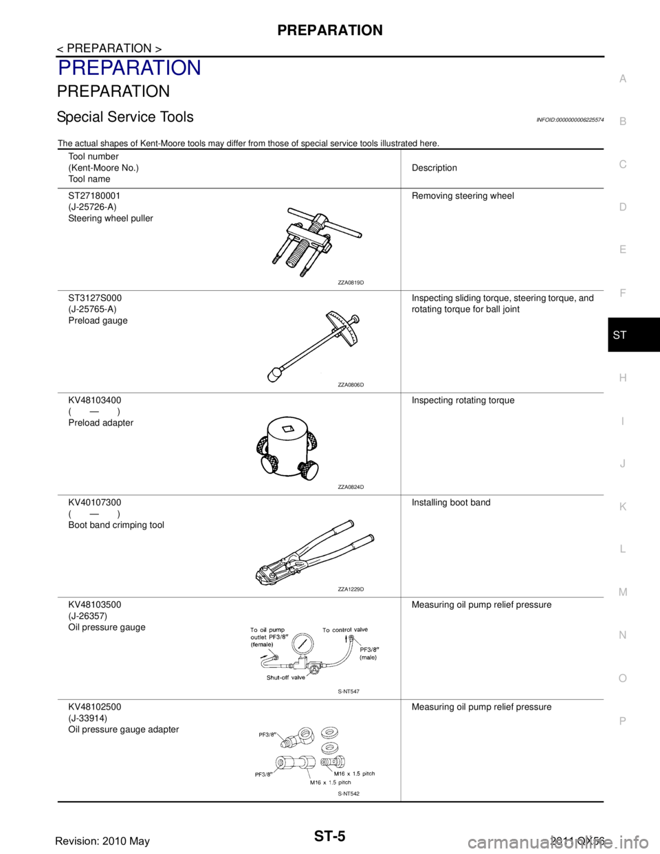
The actual shapes of Kent-Moore t ools may differ from those of special service tools illustrated here.
Tool number
(Kent-Moore No.)
Tool name Description
ST27180001
(J-25726-A)
Steering wheel puller Removing steering wheel
ST3127S000
(J-25765-A)
Preload gauge Inspecting sliding torque, steering torque, and
rotating torque for ball joint
KV48103400
(—)
Preload adapter Inspecting rotating torque
KV40107300
(—)
Boot band crimping tool Installing boot band
KV48103500
(J-26357)
Oil pressure gauge Measuring oil pump relief pressure
KV48102500
(J-33914)
Oil pressure gauge adapter Measuring oil pump relief pressure
ZZA0819D
ZZA0806D
ZZA0824D
ZZA1229D
S-NT547
S-NT542
Revision: 2010 May2011 QX56
Page 4993 of 5598
ST-6
< PREPARATION >
PREPARATION
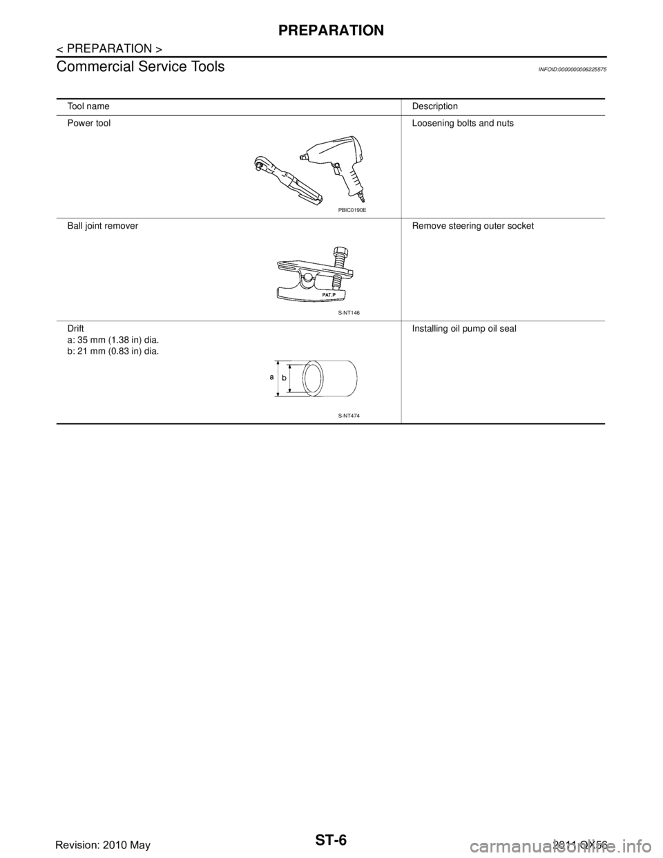
Commercial Service Tools
INFOID:0000000006225575
Tool name Description
Power tool Loosening bolts and nuts
Ball joint remover Remove steering outer socket
Drift
a: 35 mm (1.38 in) dia.
b: 21 mm (0.83 in) dia. Installing oil pump oil seal
PBIC0190E
S-NT146
S-NT474
Revision: 2010 May2011 QX56
Page 5001 of 5598
ST-14
< BASIC INSPECTION >
STEERING WHEEL
STEERING WHEEL
InspectionINFOID:0000000006225584
NEUTRAL POSITION STEERING WHEEL
1. Check that steering gear assembly, steering column assembly and steering wheel are installed in the cor-
rect position.
2. Perform neutral position inspection after wheel alignment. Refer to FSU-7, "
Inspection".
3. Set vehicle to the straight-ahead position and c onfirm steering wheel is in the neutral position.
4. Loosen outer socket lock nut and turn inner socket to left and right equally to make fine adjustments if steering wheel is not in the neutral position.
STEERING WHEEL TURNING FORCE
1. Park vehicle on a level and dry surface, set parking brake.
2. Tires need to be inflated the specified pressure. Refer to WT-69, "
Tire Air Pressure".
3. Start the engine.
4. Bring power steering fluid up to adequate operating temperature.
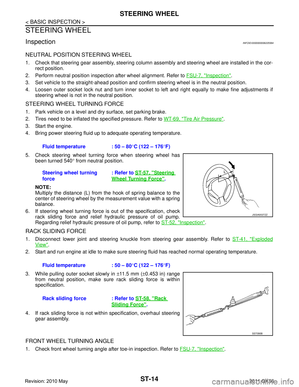
5. Check steering wheel turning force when steering wheel has been turned 540 ° from neutral position.
NOTE:
Multiply the distance (L) from the hook of spring balance to the
center of steering wheel by the measurement value with a spring
balance.
6. If steering wheel turning force is out of the specification, check
rack sliding force and relief hydraulic pressure of oil pump.
Regarding relief hydraulic pressure of oil pump, refer to ST-52, "
Inspection".
RACK SLIDING FORCE
1. Disconnect lower joint and steering knuckle from steering gear assembly. Refer to ST-41, "Exploded
View".
2. Start and run engine at idle to make sure steer ing fluid has reached normal operating temperature.
3. While pulling outer socket slowly in ±11.5 mm ( ±0.453 in) range
from neutral position, make sure rack sliding force is within
specification.
4. If rack sliding force is not within specification, overhaul steering gear assembly.
FRONT WHEEL TURNING ANGLE
1. Check front wheel turning angle after toe-in inspection. Refer to FSU-7, "Inspection".
Fluid temperature : 50 – 80
°C (122 – 176 °F)
Steering wheel turning
force : Refer to
ST-57, "
Steering
Wheel Turning Force".
JSGIA0027ZZ
Fluid temperature : 50 – 80 °C (122 – 176 °F)
Rack sliding force : Refer to ST-58, "
Rack
Sliding Force".
SST090B
Revision: 2010 May2011 QX56