2011 INFINITI QX56 turn signal
[x] Cancel search: turn signalPage 1688 of 5598

DLK-152
< DTC/CIRCUIT DIAGNOSIS >
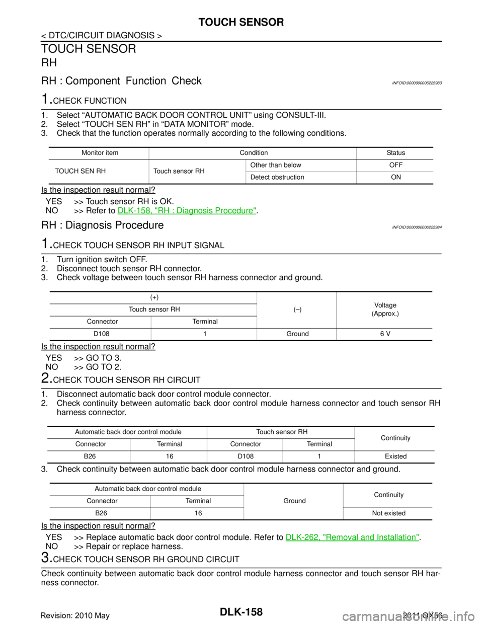
AUTOMATIC BACK DOOR MAIN SWITCH
AUTOMATIC BACK DOOR MAIN SWITCH
Component Function CheckINFOID:0000000006225974
1.CHECK FUNCTION
1. Select “AUTOMATIC BACK DOOR CONTROL UNIT” using CONSULT-III.
2. Select “MAIN SW” in “DATA MONITOR” mode.
3. Check that the function operates normall y according to the following conditions.
Is the inspection result normal?
YES >> Automatic back door main switch is OK.
NO >> Refer to DLK-152, "
Diagnosis Procedure".
Diagnosis ProcedureINFOID:0000000006225975
1.CHECK AUTOMATIC BACK DOOR MAIN SWITCH INPUT SIGNAL
1. Turn ignition switch OFF.
2. Disconnect automatic back door main switch connector.
3. Check voltage between automatic back door main switch harness connector and ground.
Is the inspection result normal?
YES >> GO TO 3.
NO >> GO TO 2.
2.CHECK AUTOMATIC BACK DO OR MAIN SWITCH CIRCUIT
1. Disconnect automatic back door control module connector.
2. Check continuity between automatic back door control module harness connector and automatic back
door main switch harness connector.
3. Check continuity between automatic back door control module connector and ground.
Is the inspection result normal?
YES >> Replace automatic back door control module. Refer to DLK-262, "Removal and Installation".
NO >> Repair or replace harness.
3.CHECK AUTOMATIC BACK DOOR MAIN SWITCH GROUND CIRCUIT
Check continuity between automatic back door main switch connector and ground.
Monitor item Condition Status
MAIN SW Automatic back door main switch ON ON
OFF OFF
(+)
(–)Voltag e
(Approx.)
Automatic back door main switch
Connector Terminal M110 1 Ground Battery voltage
Automatic back door control module Automatic back door main switch Continuity
Connector Terminal Connector Terminal
B26 17 M110 1 Existed
Automatic back door control module GroundContinuity
Connector Terminal
B26 17 Not existed
Revision: 2010 May2011 QX56
Page 1690 of 5598

DLK-154
< DTC/CIRCUIT DIAGNOSIS >
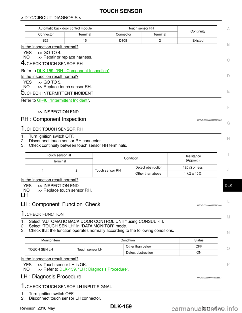
AUTOMATIC BACK DOOR SWITCH
AUTOMATIC BACK DOOR SWITCH
Component Function CheckINFOID:0000000006225977
1.CHECK FUNCTION
1. Select “AUTOMATIC BACK DOOR CONTROL UNIT” using CONSULT-III.
2. Select “AUTO BD SW” in “DATA MONITOR” mode.
3. Check that the function operates normall y according to the following conditions.
Is the inspection result normal?
YES >> Automatic back door switch is OK.
NO >> Refer to DLK-154, "
Diagnosis Procedure".
Diagnosis ProcedureINFOID:0000000006225978
1.CHECK AUTOMATIC BACK DOOR SWITCH INPUT SIGNAL
1. Turn ignition switch OFF.
2. Disconnect automatic back door switch connector.
3. Check voltage between automatic back door switch harness connector and ground.
Is the inspection result normal?
YES >> GO TO 3.
NO >> GO TO 2.
2.CHECK AUTOMATIC BACK DOOR SWITCH CIRCUIT
1. Disconnect automatic back door control module connector.
2. Check continuity between automatic back door control module harness connector and automatic back
door switch harness connector.
3. Check continuity between automatic back door control module harness connector and ground.
Is the inspection result normal?
YES >> Replace automatic back door control module. Refer to DLK-262, "Removal and Installation".
NO >> Repair or replace harness.
3.CHECK AUTOMATIC BACK DOOR SWITCH GROUND CIRCUIT
Check continuity between automatic bac k door switch harness connector and ground.
Monitor item Condition Status
AUTO BD SW Automatic back door switch Pressed ON
Released OFF
(+)
(–)Vo l ta g e
(Approx.)
Automatic back door switch
Connector Terminal M127 1 Ground Battery voltage
Automatic back door control module Automatic back door switch Continuity
Connector Terminal Connector Terminal
B26 2 M127 1 Existed
Automatic back door control module GroundContinuity
Connector Terminal
B26 2 Not existed
Revision: 2010 May2011 QX56
Page 1692 of 5598

DLK-156
< DTC/CIRCUIT DIAGNOSIS >
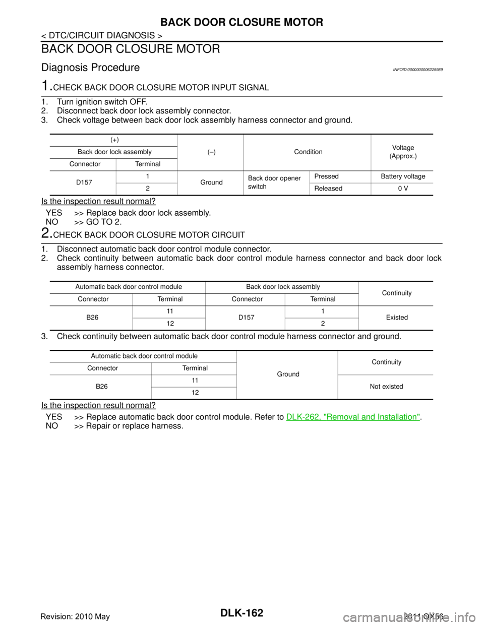
HALF LATCH SWITCH
HALF LATCH SWITCH
Component Function CheckINFOID:0000000006225980
1.CHECK FUNCTION
1. Select “AUTOMATIC BACK DOOR CONTROL UNIT” using CONSULT-III.
2. Select “HALF LATCH SW” in “DATA MONITOR” mode.
3. Check that the function operates normall y according to the following conditions.
Is the inspection result normal?
YES >> Half latch switch is OK.
NO >> Refer to DLK-156, "
Diagnosis Procedure".
Diagnosis ProcedureINFOID:0000000006225981
1.CHECK HALF LATCH SWITCH INPUT SIGNAL
1. Turn ignition switch OFF.
2. Disconnect back door lock assembly connector.
3. Check voltage between back door lock assembly harness connector and ground.
Is the inspection result normal?
YES >> GO TO 3.
NO >> GO TO 2.
2.CHECK HALF LATCH SWITCH CIRCUIT
1. Disconnect automatic back door control module connector.
2. Check continuity between automatic back door control module harness connector.
3. Check continuity between automatic back door control module harness connector and ground.
Is the inspection result normal?
YES >> Replace automatic back door control module. Refer to DLK-262, "Removal and Installation".
NO >> Repair or replace harness.
3.CHECK HALF LATCH SWITCH GROUND CIRCUIT
Check continuity between back door lock assembly harness connector and ground.
Monitor item Condition Status
HALF LATCH SW Back door Fully closed/Half latch OFF
Open ON
(–)
(–)Voltag e
(Approx.)
Back door lock assembly
Connector Terminal D157 6 Ground Battery voltage
Automatic back door control module Back door lock assembly Continuity
Connector Terminal Connector Terminal
B26 8 D157 6 Existed
Automatic back door control module GroundContinuity
Connector Terminal
B26 8 Not existed
Back door lock assembly GroundContinuity
Connector Terminal
D157 8 Existed
Revision: 2010 May2011 QX56
Page 1694 of 5598

DLK-158
< DTC/CIRCUIT DIAGNOSIS >
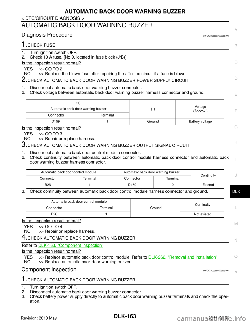
TOUCH SENSOR
TOUCH SENSOR
RH
RH : Component Function CheckINFOID:0000000006225983
1.CHECK FUNCTION
1. Select “AUTOMATIC BACK DOOR CONTROL UNIT” using CONSULT-III.
2. Select “TOUCH SEN RH” in “DATA MONITOR” mode.
3. Check that the function operates normall y according to the following conditions.
Is the inspection result normal?
YES >> Touch sensor RH is OK.
NO >> Refer to DLK-158, "
RH : Diagnosis Procedure".
RH : Diagnosis ProcedureINFOID:0000000006225984
1.CHECK TOUCH SENSOR RH INPUT SIGNAL
1. Turn ignition switch OFF.
2. Disconnect touch sensor RH connector.
3. Check voltage between touch sensor RH harness connector and ground.
Is the inspection result normal?
YES >> GO TO 3.
NO >> GO TO 2.
2.CHECK TOUCH SENSOR RH CIRCUIT
1. Disconnect automatic back door control module connector.
2. Check continuity between automatic back door c ontrol module harness connector and touch sensor RH
harness connector.
3. Check continuity between automatic back door control module harness connector and ground.
Is the inspection result normal?
YES >> Replace automatic back door control module. Refer to DLK-262, "Removal and Installation".
NO >> Repair or replace harness.
3.CHECK TOUCH SENSOR RH GROUND CIRCUIT
Check continuity between automatic back door cont rol module harness connector and touch sensor RH har-
ness connector.
Monitor item Condition Status
TOUCH SEN RH Touch sensor RH Other than below OFF
Detect obstruction ON
(+)
(–)Vol tag e
(Approx.)
Touch sensor RH
Connector Terminal D108 1 Ground 6 V
Automatic back door control module Touch sensor RH Continuity
Connector Terminal Connector Terminal
B26 16 D108 1 Existed
Automatic back door control module GroundContinuity
Connector Terminal
B26 16 Not existed
Revision: 2010 May2011 QX56
Page 1695 of 5598

TOUCH SENSORDLK-159
< DTC/CIRCUIT DIAGNOSIS >
C
DE
F
G H
I
J
L
M A
B
DLK
N
O P
Is the inspection result normal?
YES >> GO TO 4.
NO >> Repair or replace harness.
4.CHECK TOUCH SENSOR RH
Refer to DLK-159, "
RH : Component Inspection".
Is the inspection result normal?
YES >> GO TO 5.
NO >> Replace touch sensor RH.
5.CHECK INTERMITTENT INCIDENT
Refer to GI-40, "
Intermittent Incident".
>> INSPECTION END
RH : Component InspectionINFOID:0000000006225985
1.CHECK TOUCH SENSOR RH
1. Turn ignition switch OFF.
2. Disconnect touch sensor RH connector.
3. Check continuity between touch sensor RH terminals.
Is the inspection result normal?
YES >> INSPECTION END
NO >> Replace touch sensor RH.
LH
LH : Component Function CheckINFOID:0000000006225986
1.CHECK FUNCTION
1. Select “AUTOMATIC BACK DOOR CONTROL UNIT” using CONSULT-III.
2. Select “TOUCH SEN LH” in “DATA MONITOR” mode.
3. Check that the function operates normall y according to the following conditions.
Is the inspection result normal?
YES >> Touch sensor LH is OK.
NO >> Refer to DLK-159, "
LH : Diagnosis Procedure".
LH : Diagnosis ProcedureINFOID:0000000006225987
1.CHECK TOUCH SENSOR LH INPUT SIGNAL
1. Turn ignition switch OFF.
2. Disconnect touch sensor LH connector.
Automatic back door control module Touch sensor RH Continuity
Connector Terminal Connector Terminal
B26 15 D108 2 Existed
Touch sensor RH ConditionResistance
(Approx.)
Te r m i n a l
1 2 Touch sensor RH Detect obstruction 120
Ω or less
Other than above 1 k Ω ± 10%
Monitor item Condition Status
TOUCH SEN LH Touch sensor LH Other than below OFF
Detect obstruction ON
Revision: 2010 May2011 QX56
Page 1698 of 5598

DLK-162
< DTC/CIRCUIT DIAGNOSIS >
BACK DOOR CLOSURE MOTOR
BACK DOOR CLOSURE MOTOR
Diagnosis ProcedureINFOID:0000000006225989
1.CHECK BACK DOOR CLOSURE MOTOR INPUT SIGNAL
1. Turn ignition switch OFF.
2. Disconnect back door lock assembly connector.
3. Check voltage between back door lock assembly harness connector and ground.
Is the inspection result normal?
YES >> Replace back door lock assembly.
NO >> GO TO 2.
2.CHECK BACK DOOR CLOSURE MOTOR CIRCUIT
1. Disconnect automatic back door control module connector.
2. Check continuity between automatic back door control module harness connector and back door lock
assembly harness connector.
3. Check continuity between automatic back door control module harness connector and ground.
Is the inspection result normal?
YES >> Replace automatic back door control module. Refer to DLK-262, "Removal and Installation".
NO >> Repair or replace harness.
(+)
(–) Condition Voltag e
(Approx.)
Back door lock assembly
Connector Terminal
D157 1
GroundBack door opener
switch Pressed Battery voltage
2Released0 V
Automatic back door control module Back door lock assembly Continuity
Connector Terminal Connector Terminal
B26 11
D157 1
Existed
12 2
Automatic back door control module GroundContinuity
Connector Terminal
B26 11
Not existed
12
Revision: 2010 May2011 QX56
Page 1699 of 5598

AUTOMATIC BACK DOOR WARNING BUZZERDLK-163
< DTC/CIRCUIT DIAGNOSIS >
C
DE
F
G H
I
J
L
M A
B
DLK
N
O P
AUTOMATIC BACK DOOR WARNING BUZZER
Diagnosis ProcedureINFOID:0000000006225990
1.CHECK FUSE
1. Turn ignition switch OFF.
2. Check 10 A fuse, [No.9, located in fuse block (J/B)].
Is the inspection result normal?
YES >> GO TO 2.
NO >> Replace the blown fuse after repairing the affected circuit if a fuse is blown.
2.CHECK AUTOMATIC BACK DOOR WARNI NG BUZZER POWER SUPPLY CIRCUIT
1. Disconnect automatic back door warning buzzer connector.
2. Check voltage between automatic back door warning buzzer harness connector and ground.
Is the inspection result normal?
YES >> GO TO 3.
NO >> Repair or replace harness.
3.CHECK AUTOMATIC BACK DOOR WARNING BUZZER OUTPUT SIGNAL CIRCUIT
1. Disconnect automatic back door control module connector.
2. Check continuity between automatic back door control module harness connector and automatic back
door warning buzzer harness connector.
3. Check continuity between automatic back door control module harness connector and ground.
Is the inspection result normal?
YES >> GO TO 4.
NO >> Repair or replace harness.
4.CHECK AUTOMATIC BACK DOOR WARNING BUZZER
Refer to DLK-163, "
Component Inspection"
Is the inspection result normal?
YES >> Replace automatic back door control module. Refer to DLK-262, "Removal and Installation".
NO >> Replace automatic back door warning buzzer.
Component InspectionINFOID:0000000006225991
1.CHECK AUTOMATIC BACK DOOR WARNING BUZZER
1. Turn ignition switch OFF.
2. Disconnect automatic back door warning buzzer connector.
3. Check battery power supply directly to automatic back door warning buzzer terminals and check the oper-
ation.
(+)
(–)Voltag e
(Approx.)
Automatic back door warning buzzer
Connector Terminal D159 1 Ground Battery voltage
Automatic back door control module Automatic back door warning buzzer Continuity
Connector Terminal Connector Terminal
B26 1 D159 2 Existed
Automatic back door control module GroundContinuity
Connector Terminal
B26 1 Not existed
Revision: 2010 May2011 QX56
Page 1813 of 5598
![INFINITI QX56 2011 Factory Service Manual
COMPONENT PARTSDLN-11
< SYSTEM DESCRIPTION > [TRANSFER: ATX90A]
C
EF
G H
I
J
K L
M A
B
DLN
N
O P
Component DescriptionINFOID:0000000006222215
Transfer Control UnitINFOID:0000000006222216
Transfer c INFINITI QX56 2011 Factory Service Manual
COMPONENT PARTSDLN-11
< SYSTEM DESCRIPTION > [TRANSFER: ATX90A]
C
EF
G H
I
J
K L
M A
B
DLN
N
O P
Component DescriptionINFOID:0000000006222215
Transfer Control UnitINFOID:0000000006222216
Transfer c](/manual-img/42/57033/w960_57033-1812.png)
COMPONENT PARTSDLN-11
< SYSTEM DESCRIPTION > [TRANSFER: ATX90A]
C
EF
G H
I
J
K L
M A
B
DLN
N
O P
Component DescriptionINFOID:0000000006222215
Transfer Control UnitINFOID:0000000006222216
Transfer control unit operates transfer control act uator, 4WD warning lamp and 4WD mode indicator lamp
according to input signal from 4WD shift switch and each sensor and control unit.
When 4WD system is malfunctioning, 4WD warning la mp turns ON and fail-safe status activates.
When protection is necessary, 4WD warning la mp blinks and protection status activates.
Transfer Control ActuatorINFOID:0000000006222217
Transfer control actuator integrates transfer motor, transfer internal position sensor, and transfer motor tem-
perature sensor, and switches 4WD mode (AUTO ⇔4H ⇔4L).
TRANSFER MOTOR
Transfer motor operates according to signal from transfer control unit and switches 4WD mode
(AUTO ⇔4H ⇔4L). It also performs front and rear distri bution of traction force during AUTO mode.
TRANSFER INTERNAL SPEED SENSOR
Transfer internal speed sensor detects rotation status of transfer motor and transmits signal to transfer control
unit.
TRANSFER MOTOR TEMPERATURE SENSOR
Transfer motor temperature sensor m easures temperature of transfer motor.
Component parts Reference/Function
Transfer control unit DLN-11, "
Transfer Control Unit"
Transfer control actua-
torTransfer motor
DLN-11, "
Transfer Control Actuator"
Transfer internal speed
sensorDLN-11, "Transfer Control Actuator"
Transfer motor temper-
ature sensor
DLN-11, "Transfer Control Actuator"
Transfer Hi-Lo position sensor
DLN-12, "Transfer Hi-Lo Position Sensor"
Transfer rotary position sensorDLN-12, "Transfer Rotary Position Sensor"
Transfer lock position sensorDLN-12, "Transfer Lock Position Sensor"
Transfer fluid temperature sensorDLN-12, "Transfer Fluid Temperature Sensor"
4WD mode switchDLN-18, "4WD SYSTEM : System Description"
4WD indicator lampDLN-18, "4WD SYSTEM : System Description"
4WD warning lampDLN-18, "4WD SYSTEM : System Description"
AT P w a r n i n g l a m pDLN-18, "4WD SYSTEM : System Description"
ABS actuator and electric unit (control unit)Transmits the following signals via CAN communication line to transfer control unit.
Vehicle speed signal (ABS)
Stop lamp switch signal (brake signal)
ABS operation signal
VDC operation signal
TCS operation signal
Steering angle sensor Transmits the following signals via CAN communication line to transfer control unit.
Steering angle sensor signal
ECM Transmits the following signals via CAN communication line to transfer control unit.
Accelerator pedal position signal
Engine speed signal
Engine torque signal
TCM Transmits the following signals via CAN communication line to transfer control unit.
Shift position signal
Gear position signal
Output shaft revolution signal
Revision: 2010 May2011 QX56