2011 INFINITI QX56 service
[x] Cancel search: servicePage 4248 of 5598
RF-34
< REMOVAL AND INSTALLATION >
GLASS LID
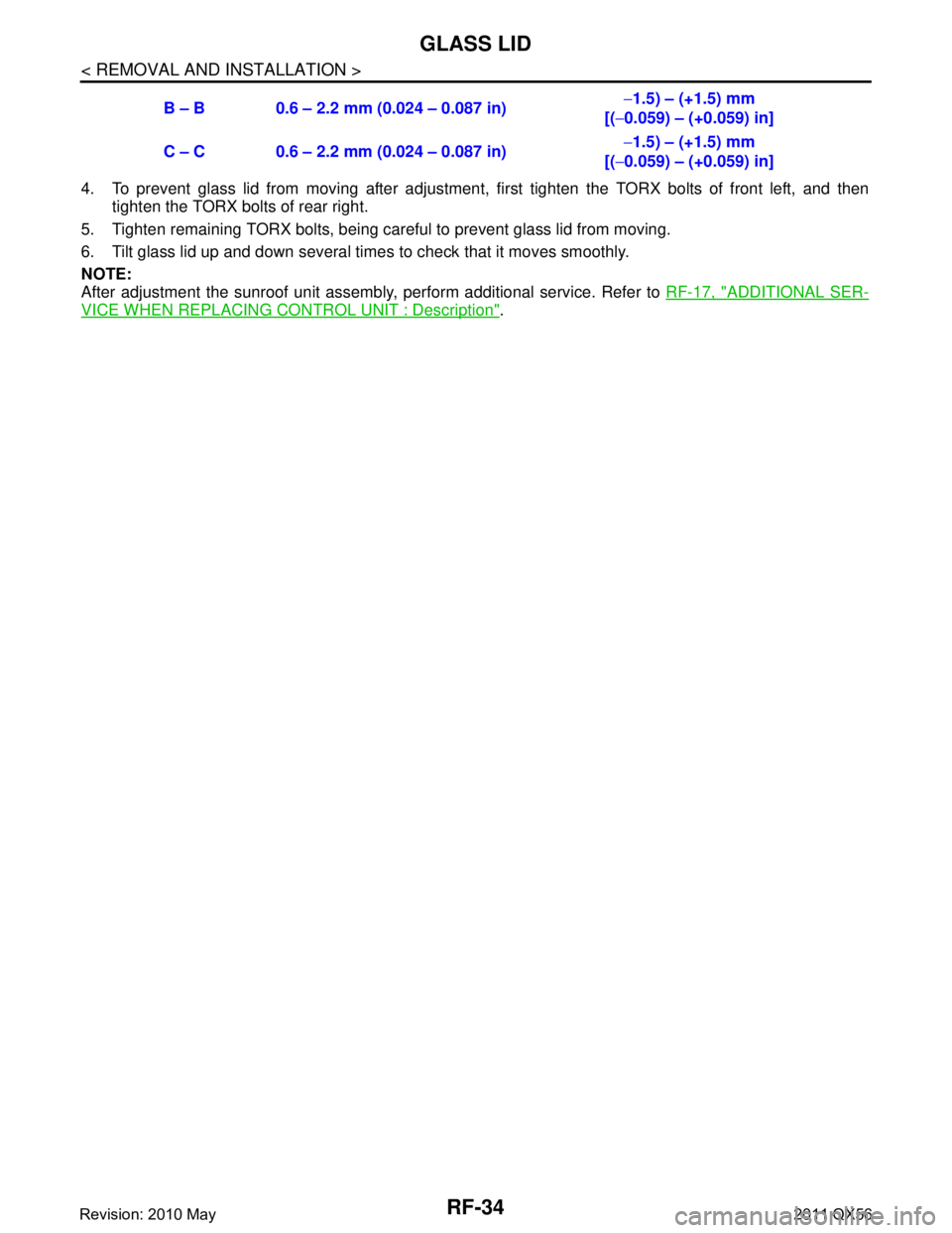
4. To prevent glass lid from moving after adjustment, first tighten the TORX bolts of front left, and then
tighten the TORX bolts of rear right.
5. Tighten remaining TORX bolts, being careful to prevent glass lid from moving.
6. Tilt glass lid up and down several times to check that it moves smoothly.
NOTE:
After adjustment the sunroof unit assembly, perform additional service. Refer to RF-17, "
ADDITIONAL SER-
VICE WHEN REPLACING CONTROL UNIT : Description".
B – B 0.6 – 2.2 mm (0.024 – 0.087 in)
−
1.5) – (+1.5) mm
[( −0.059) – (+0.059) in]
C – C 0.6 – 2.2 mm (0.024 – 0.087 in) −
1.5) – (+1.5) mm
[( −0.059) – (+0.059) in]
Revision: 2010 May2011 QX56
Page 4256 of 5598
RSU-1
SUSPENSION
C
DF
G H
I
J
K L
M
SECTION RSU
A
B
RSU
N
O PCONTENTS
REAR SUSPENSION
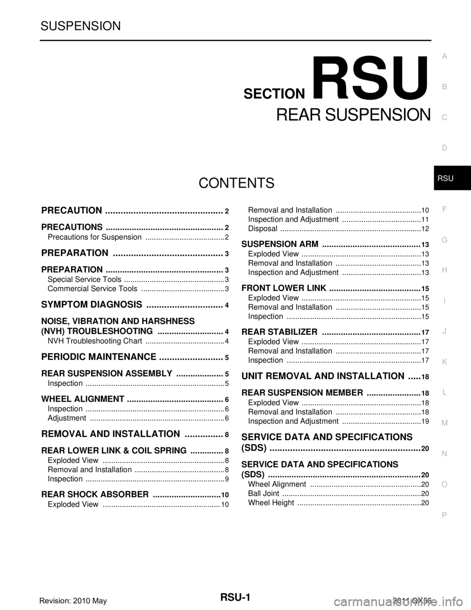
PRECAUTION ................ ...............................2
PRECAUTIONS .............................................. .....2
Precautions for Suspension ................................ ......2
PREPARATION ............................................3
PREPARATION .............................................. .....3
Special Service Tools .......................................... ......3
Commercial Service Tools ........................................3
SYMPTOM DIAGNOSIS ...............................4
NOISE, VIBRATION AND HARSHNESS
(NVH) TROUBLESHOOTING ........................ .....
4
NVH Troubleshooting Chart ................................ ......4
PERIODIC MAINTENANCE ..........................5
REAR SUSPENSION ASSEMBLY ................ .....5
Inspection ............................................................ ......5
WHEEL ALIGNMENT ..........................................6
Inspection ............................................................ ......6
Adjustment ................................................................6
REMOVAL AND INSTALLATION ................8
REAR LOWER LINK & COIL SPRING .......... .....8
Exploded View .................................................... ......8
Removal and Installation ...........................................8
Inspection ..................................................................9
REAR SHOCK ABSORBER ..............................10
Exploded View .................................................... ....10
Removal and Installation ..................................... ....10
Inspection and Adjustment ......................................11
Disposal ...................................................................12
SUSPENSION ARM ..........................................13
Exploded View .........................................................13
Removal and Installation .........................................13
Inspection and Adjustment ......................................13
FRONT LOWER LINK .......................................15
Exploded View .........................................................15
Removal and Installation .........................................15
Inspection ................................................................15
REAR STABILIZER ..........................................17
Exploded View .........................................................17
Removal and Installation .........................................17
Inspection ................................................................17
UNIT REMOVAL AND INSTALLATION ......18
REAR SUSPENSION MEMBER .......................18
Exploded View ..................................................... ....18
Removal and Installation .........................................18
Inspection and Adjustment ......................................19
SERVICE DATA AND SPECIFICATIONS
(SDS) ............... .............................................
20
SERVICE DATA AND SPECIFICATIONS
(SDS) .................................................................
20
Wheel Alignment ................................................. ....20
Ball Joint ..................................................................20
Wheel Height ...........................................................20
Revision: 2010 May2011 QX56
Page 4258 of 5598
PREPARATIONRSU-3
< PREPARATION >
C
DF
G H
I
J
K L
M A
B
RSU
N
O P
PREPARATION
PREPARATION
Special Service ToolsINFOID:0000000006225657
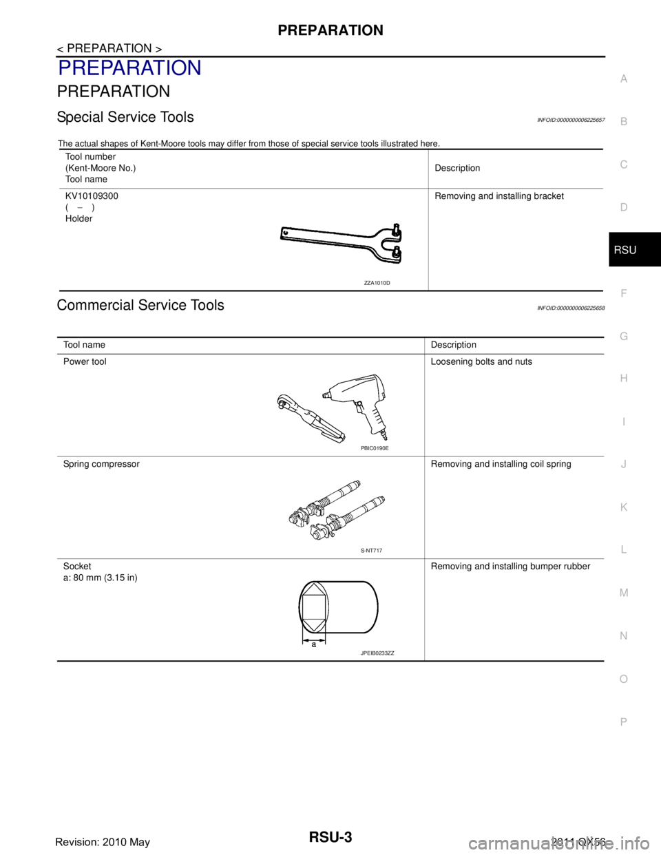
The actual shapes of Kent-Moore t ools may differ from those of special service tools illustrated here.
Commercial Service ToolsINFOID:0000000006225658
Tool number
(Kent-Moore No.)
Tool name Description
KV10109300
( − )
Holder Removing and installing bracket
ZZA1010D
Tool name
Description
Power tool Loosening bolts and nuts
Spring compressor Removing and installing coil spring
Socket
a: 80 mm (3.15 in) Removing and installing bumper rubber
PBIC0190E
S-NT717
JPEIB0233ZZ
Revision: 2010 May2011 QX56
Page 4261 of 5598
RSU-6
< PERIODIC MAINTENANCE >
WHEEL ALIGNMENT
WHEEL ALIGNMENT
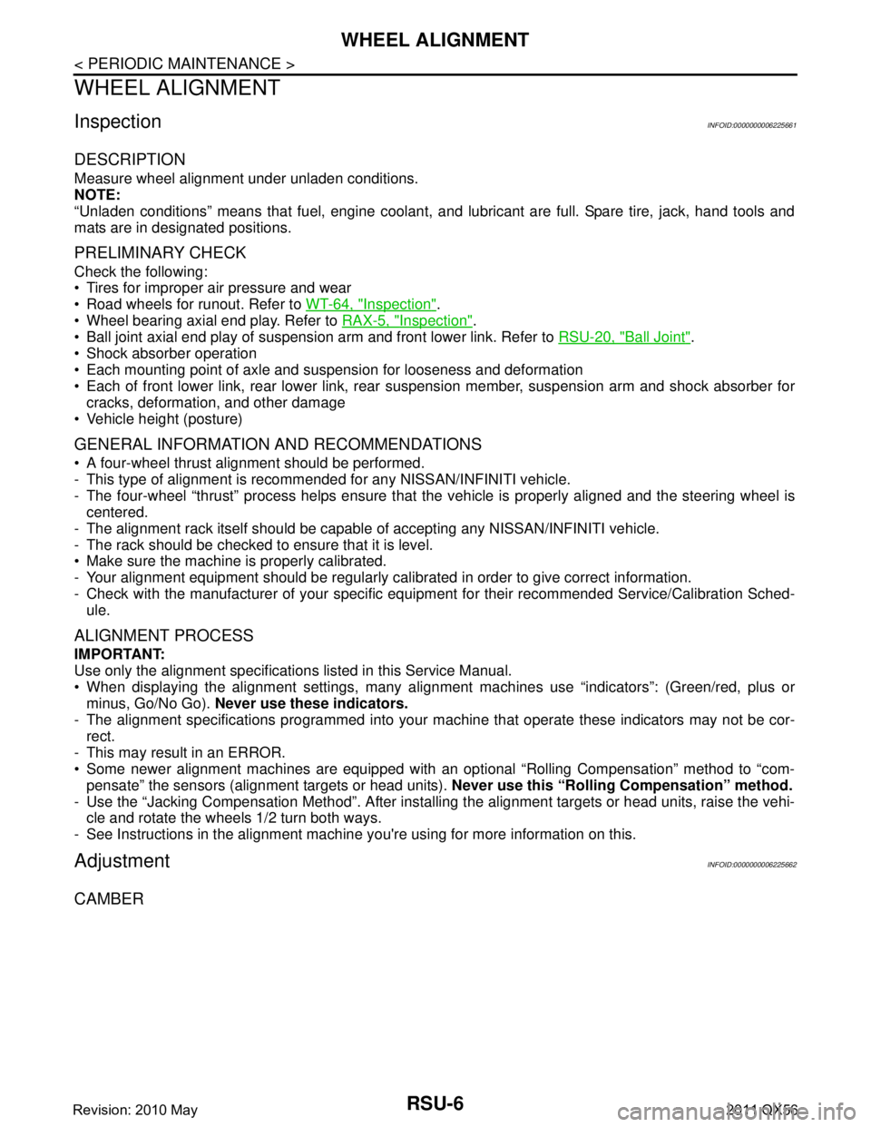
InspectionINFOID:0000000006225661
DESCRIPTION
Measure wheel alignment under unladen conditions.
NOTE:
“Unladen conditions” means that fuel, engine coolant, and lubricant are full. Spare tire, jack, hand tools and
mats are in designated positions.
PRELIMINARY CHECK
Check the following:
Tires for improper air pressure and wear
Road wheels for runout. Refer to WT-64, "
Inspection".
Wheel bearing axial end play. Refer to RAX-5, "
Inspection".
Ball joint axial end play of suspension arm and front lower link. Refer to RSU-20, "
Ball Joint".
Shock absorber operation
Each mounting point of axle and suspension for looseness and deformation
Each of front lower link, rear lower link, rear suspension member, suspension arm and shock absorber for
cracks, deformation, and other damage
Vehicle height (posture)
GENERAL INFORMATION AND RECOMMENDATIONS
A four-wheel thrust alignment should be performed.
- This type of alignment is recomm ended for any NISSAN/INFINITI vehicle.
- The four-wheel “thrust” process helps ensure that t he vehicle is properly aligned and the steering wheel is
centered.
- The alignment rack itself should be capable of accepting any NISSAN/INFINITI vehicle.
- The rack should be checked to ensure that it is level.
Make sure the machine is properly calibrated.
- Your alignment equipment should be regularly calib rated in order to give correct information.
- Check with the manufacturer of your specific equi pment for their recommended Service/Calibration Sched-
ule.
ALIGNMENT PROCESS
IMPORTANT:
Use only the alignment specifications listed in this Service Manual.
When displaying the alignment settings, many alignment machines use “indicators”: (Green/red, plus or
minus, Go/No Go). Never use these indicators.
- The alignment specifications programmed into your machine that operate these indicators may not be cor-
rect.
- This may result in an ERROR.
Some newer alignment machines are equipped with an optional “Rolling Compensation” method to “com- pensate” the sensors (alignment targets or head units). Never use this “Rolling Compensation” method.
- Use the “Jacking Compensation Method”. After installi ng the alignment targets or head units, raise the vehi-
cle and rotate the wheels 1/2 turn both ways.
- See Instructions in the alignment machine you're using for more information on this.
AdjustmentINFOID:0000000006225662
CAMBER
Revision: 2010 May2011 QX56
Page 4263 of 5598
RSU-8
< REMOVAL AND INSTALLATION >
REAR LOWER LINK & COIL SPRING
REMOVAL AND INSTALLATION
REAR LOWER LINK & COIL SPRING
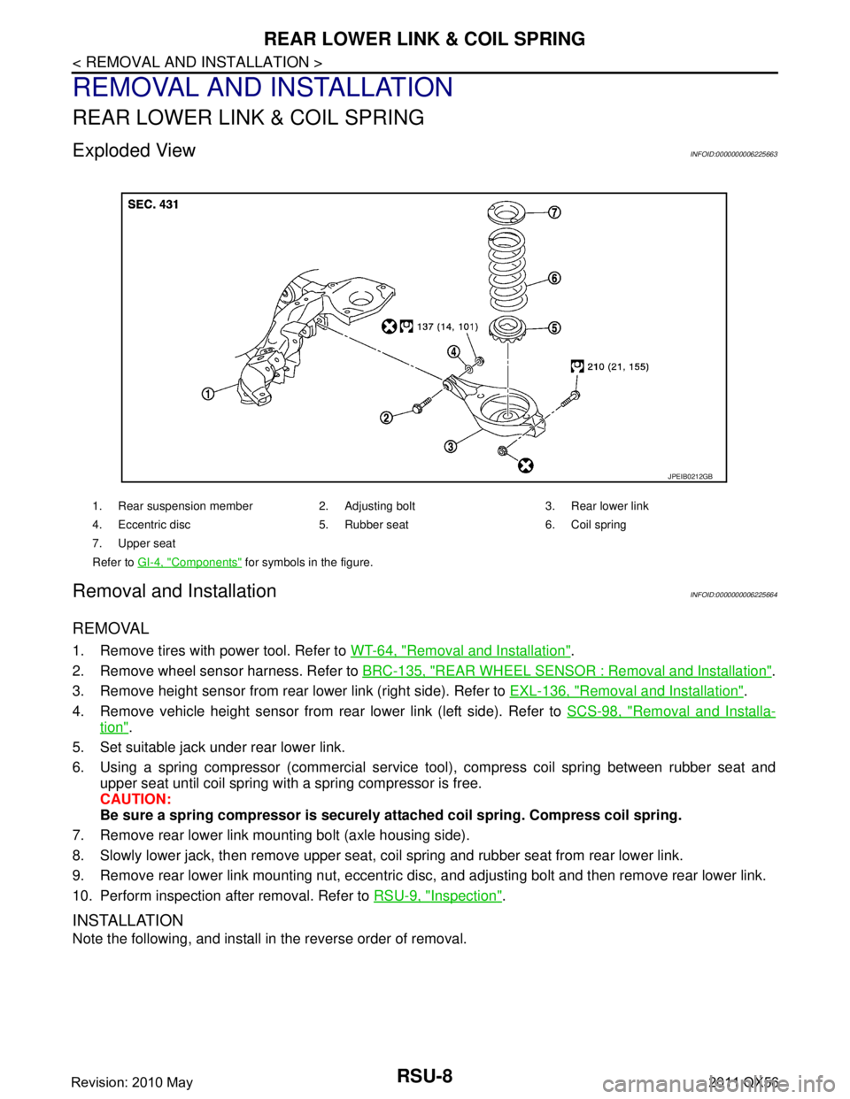
Exploded ViewINFOID:0000000006225663
Removal and InstallationINFOID:0000000006225664
REMOVAL
1. Remove tires with power tool. Refer to WT-64, "Removal and Installation".
2. Remove wheel sensor harness. Refer to BRC-135, "
REAR WHEEL SENSOR : Removal and Installation".
3. Remove height sensor from rear lower link (right side). Refer to EXL-136, "
Removal and Installation".
4. Remove vehicle height sensor from rear lower link (left side). Refer to SCS-98, "
Removal and Installa-
tion".
5. Set suitable jack under rear lower link.
6. Using a spring compressor (commercial service tool), compress coil spring between rubber seat and upper seat until coil spring with a spring compressor is free.
CAUTION:
Be sure a spring compressor is securely at tached coil spring. Compress coil spring.
7. Remove rear lower link mounting bolt (axle housing side).
8. Slowly lower jack, then remove upper seat, co il spring and rubber seat from rear lower link.
9. Remove rear lower link mounting nut, eccentric disc, and adjusting bolt and then remove rear lower link.
10. Perform inspection after removal. Refer to RSU-9, "
Inspection".
INSTALLATION
Note the following, and install in the reverse order of removal.
1. Rear suspension member 2. Adjusting bolt 3. Rear lower link
4. Eccentric disc 5. Rubber seat 6. Coil spring
7. Upper seat
Refer to GI-4, "
Components" for symbols in the figure.
JPEIB0212GB
Revision: 2010 May2011 QX56
Page 4268 of 5598
SUSPENSION ARMRSU-13
< REMOVAL AND INSTALLATION >
C
DF
G H
I
J
K L
M A
B
RSU
N
O P
SUSPENSION ARM
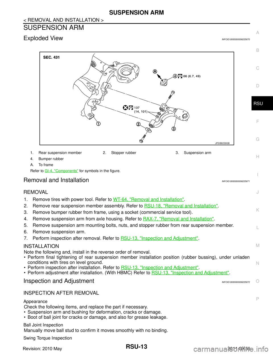
Exploded ViewINFOID:0000000006225670
Removal and InstallationINFOID:0000000006225671
REMOVAL
1. Remove tires with power tool. Refer to WT-64, "Removal and Installation".
2. Remove rear suspension member assembly. Refer to RSU-18, "
Removal and Installation".
3. Remove bumper rubber from frame, usi ng a socket (commercial service tool).
4. Remove suspension arm from axle housing. Refer to RAX-7, "
Removal and Installation".
5. Remove suspension arm mounting bolts, nuts, and stopper rubber from rear suspension member.
6. Remove suspension arm.
7. Perform inspection after removal. Refer to RSU-13, "
Inspection and Adjustment".
INSTALLATION
Note the following and, install in the reverse order of removal.
Perform final tightening of rear suspension mem ber installation position (rubber bussing), under unladen
conditions with tires on level ground.
Perform inspection after installation. Refer to RSU-13, "
Inspection and Adjustment".
Perform adjustment after installation. (With HBMC) Refer to RSU-13, "
Inspection and Adjustment".
Inspection and AdjustmentINFOID:0000000006225672
INSPECTION AFTER REMOVAL
Appearance
Check the following items, and replace the part if necessary.
Suspension arm and bushing for deformation, cracks or damage.
Boot of ball joint for cracks or damage, and also for grease leakage.
Ball Joint Inspection
Manually move ball stud to confirm it moves smoothly with no binding.
Swing Torque Inspection
1. Rear suspension member 2. Stopper rubber 3. Suspension arm
4. Bumper rubber
A. To frame
Refer to GI-4, "
Components" for symbols in the figure.
JPEIB0230GB
Revision: 2010 May2011 QX56
Page 4275 of 5598
RSU-20
< SERVICE DATA AND SPECIFICATIONS (SDS)
SERVICE DATA AND SPECIFICATIONS (SDS)
SERVICE DATA AND SPECIFICATIONS (SDS)
SERVICE DATA AND SPECIFICATIONS (SDS)
Wheel AlignmentINFOID:0000000006225679
Measure value under unladen* conditions.
*: Fuel, engine coolant and lubricant are full. Spare tire, jack, hand tools and mats are in designated positions.
Ball JointINFOID:0000000006225680
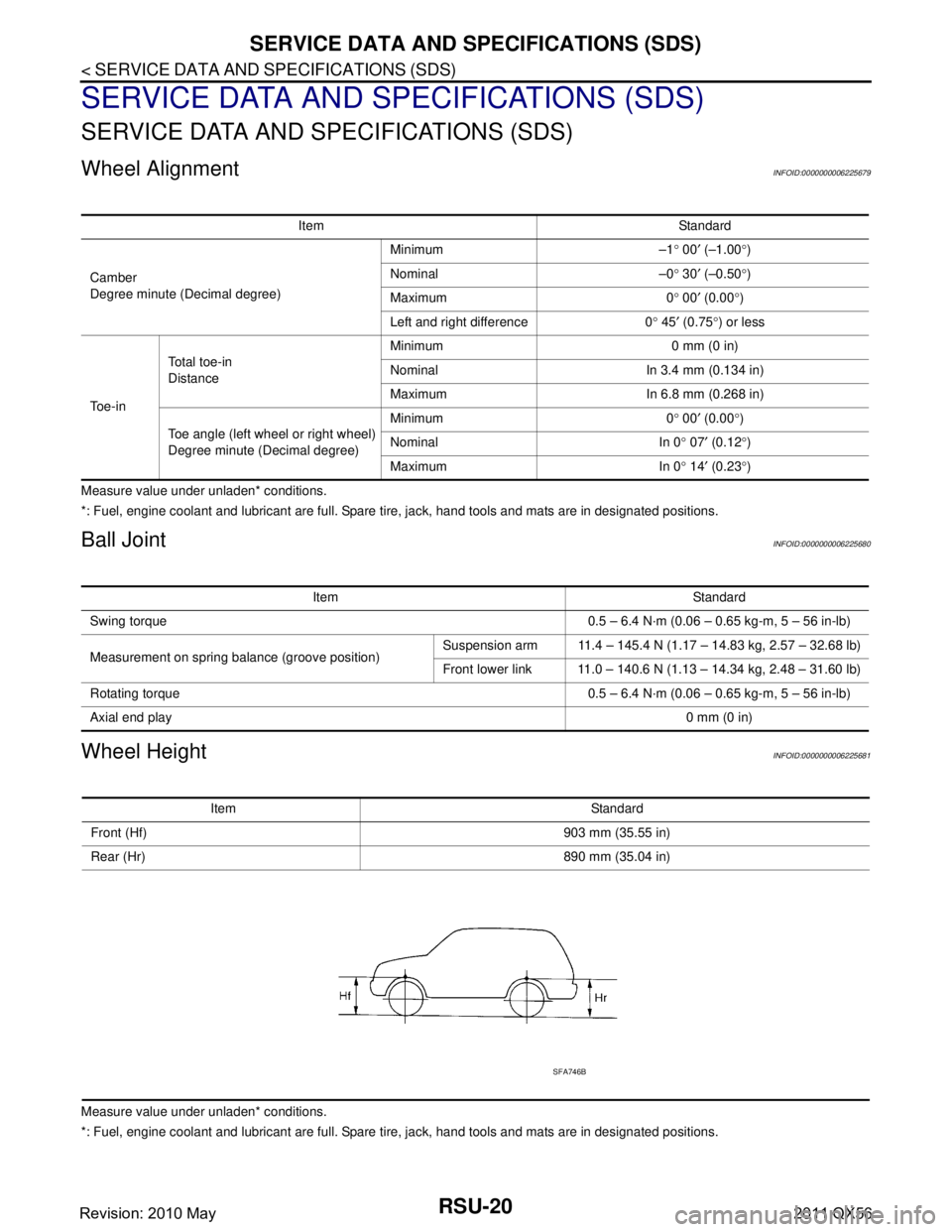
Wheel HeightINFOID:0000000006225681
Measure value under unladen* conditions.
*: Fuel, engine coolant and lubricant are full. Spare tire, jack, hand tools and mats are in designated positions.Item Standard
Camber
Degree minute (Decimal degree) Minimum –1
° 00 ′ (–1.00 °)
Nominal –0 ° 30 ′ (–0.50 °)
Maximum 0 ° 00 ′ (0.00 °)
Left and right difference 0 ° 45 ′ (0.75 °) or less
To e - i n Total toe-in
Distance
Minimum 0 mm (0 in)
Nominal In 3.4 mm (0.134 in)
Maximum In 6.8 mm (0.268 in)
Toe angle (left wheel or right wheel)
Degree minute (Decimal degree) Minimum 0
° 00 ′ (0.00 °)
Nominal In 0 ° 07 ′ (0.12 °)
Maximum In 0 ° 14 ′ (0.23 °)
Item Standard
Swing torque 0.5 – 6.4 N·m (0.06 – 0.65 kg-m, 5 – 56 in-lb)
Measurement on spring balance (groove position) Suspension arm 11.4 – 145.4 N (1.17 – 14.83 kg, 2.57 – 32.68 lb)
Front lower link 11.0 – 140.6 N (1.13 – 14.34 kg, 2.48 – 31.60 lb)
Rotating torque 0.5 – 6.4 N·m (0.06 – 0.65 kg-m, 5 – 56 in-lb)
Axial end play 0 mm (0 in)
Item Standard
Front (Hf) 903 mm (35.55 in)
Rear (Hr) 890 mm (35.04 in)
SFA746B
Revision: 2010 May2011 QX56
Page 4276 of 5598
SB-1
RESTRAINTS
C
DE
F
G
I
J
K L
M
SECTION SB
A
B
SB
N
O P
CONTENTS
SEAT BELT
PRECAUTION ................ ...............................2
PRECAUTIONS .............................................. .....2
Precaution for Supplemental Restraint System
(SRS) "AIR BAG" and "SEAT BELT PRE-TEN-
SIONER" ............................................................. ......
2
Precaution Necessary for Steering Wheel Rota-
tion after Battery Disconnect .....................................
2
Precaution for Seat Belt Service ...............................3
REMOVAL AND INSTALLATION ................4
FRONT SEAT BELT ....................................... .....4
SEAT BELT RETRACTOR .................................... ......4
SEAT BELT RETRACTOR : Inspection ....................4
SEAT BELT RETRACTOR : Exploded View .............6
SEAT BELT RETRACTOR : Removal and Instal-
lation ..........................................................................
6
SEAT BELT BUCKLE ........................................... ......7
SEAT BELT BUCKLE : Inspection ............................7
SEAT BELT BUCKLE : Exploded View .....................8
SEAT BELT BUCKLE : Removal and Installation ......8
SECOND SEAT BELT ........................................10
SEAT BELT RETRACTOR .................................... ....10
SEAT BELT RETRACTOR : Inspection ..................10
SEAT BELT RETRACTOR : Exploded View ...........11
SEAT BELT RETRACTOR : Removal and Instal-
lation ........................................................................
13
SEAT BELT BUCKLE ............................................ ....14
SEAT BELT BUCKLE : Inspection ..........................14
SEAT BELT BUCKLE : Exploded View ...................14
SEAT BELT BUCKLE : Removal and Installation ....16
THIRD SEAT BELT ...........................................17
SEAT BELT RETRACTOR .................................... ....17
SEAT BELT RETRACTOR : Inspection ..................17
SEAT BELT RETRACTOR : Exploded View ...........19
SEAT BELT RETRACTOR : Removal and Instal-
lation ........................................................................
19
SEAT BELT BUCKLE ............................................ ....20
SEAT BELT BUCKLE : Inspection ..........................20
SEAT BELT BUCKLE : Exploded View ...................21
SEAT BELT BUCKLE : Removal and Installation ....21
LATCH SYSTEM FOR CHILDREN ...................22
Exploded View .........................................................22
Removal and Installation .........................................22
Revision: 2010 May2011 QX56