2011 INFINITI QX56 service
[x] Cancel search: servicePage 4217 of 5598
PRECAUTIONSRF-3
< PRECAUTION >
C
DE
F
G H
I
J
L
M A
B
RF
N
O P
PRECAUTION
PRECAUTIONS
Precaution for Supplemental Restraint System (SRS) "AIR BAG" and "SEAT BELT
PRE-TENSIONER"
INFOID:0000000006141220
The Supplemental Restraint System such as “A IR BAG” and “SEAT BELT PRE-TENSIONER”, used along
with a front seat belt, helps to reduce the risk or severi ty of injury to the driver and front passenger for certain
types of collision. This system includes seat belt switch inputs and dual stage front air bag modules. The SRS
system uses the seat belt switches to determine the front air bag deployment, and may only deploy one front
air bag, depending on the severity of a collision and whether the front occupants are belted or unbelted.
Information necessary to service the system safely is included in the “SRS AIR BAG” and “SEAT BELT” of this
Service Manual.
WARNING:
• To avoid rendering the SRS inoper ative, which could increase the risk of personal injury or death in
the event of a collision that would result in air ba g inflation, all maintenance must be performed by
an authorized NISSAN/INFINITI dealer.
Improper maintenance, including in correct removal and installation of the SRS, can lead to personal
injury caused by unintentional act ivation of the system. For removal of Spiral Cable and Air Bag
Module, see the “SRS AIR BAG”.
Do not use electrical test equipm ent on any circuit related to the SRS unless instructed to in this
Service Manual. SRS wiring harnesses can be identi fied by yellow and/or orange harnesses or har-
ness connectors.
PRECAUTIONS WHEN USING POWER TOOLS (AIR OR ELECTRIC) AND HAMMERS
WARNING:
When working near the Air Bag Diagnosis Sensor Unit or other Air Bag System sensors with the
ignition ON or engine running, DO NOT use air or electric power tools or strike near the sensor(s)
with a hammer. Heavy vibration could activate the sensor(s) and deploy the air bag(s), possibly
causing serious injury.
When using air or electric power tools or hammers , always switch the ignition OFF, disconnect the
battery, and wait at least 3 minutes before performing any service.
Revision: 2010 May2011 QX56
Page 4218 of 5598
RF-4
< PREPARATION >
PREPARATION
PREPARATION
PREPARATION
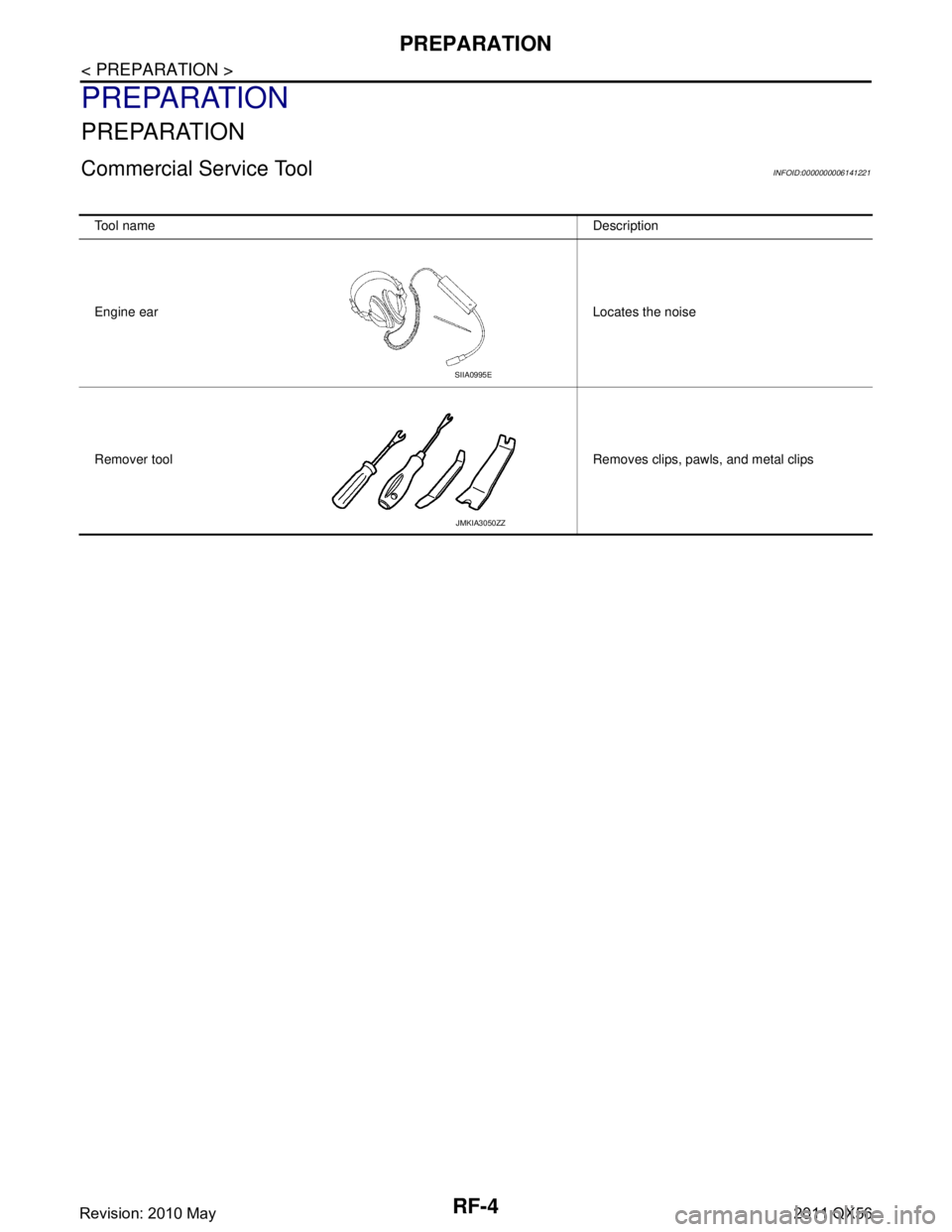
Commercial Service ToolINFOID:0000000006141221
Tool nameDescription
Engine ear Locates the noise
Remover tool Removes clips, pawls, and metal clips
SIIA0995E
JMKIA3050ZZ
Revision: 2010 May2011 QX56
Page 4231 of 5598

INSPECTION AND ADJUSTMENTRF-17
< BASIC INSPECTION >
C
DE
F
G H
I
J
L
M A
B
RF
N
O P
INSPECTION AND ADJUSTMENT
ADDITIONAL SERVICE WHEN REPLACING CONTROL UNIT
ADDITIONAL SERVICE WHEN REPL ACING CONTROL UNIT : Description
INFOID:0000000006141230
MEMORY RESET PROCEDURE
1. Please observe the following instructi ons at confirming the sunroof operation.
NOTE:
Do not disconnect the electronic power while the sunroof is operating or within 5 seconds after the sunroof
stops (to wipe-out the memory of lid position and operating friction).
2. Initialization of system should be conducted after the following conditions.
When the sunroof motor is changed.
When the sunroof does not operate normally. (Incomplete initialization conditions)
ADDITIONAL SERVICE WHEN REPLACING CONTROL UNIT : Special Repair Re-
quirement
INFOID:0000000006141231
INITIALIZATION PROCEDURE
If the sunroof does not close or open automatically, us e the following procedure to return sunroof operation to
normal.
1. Press the tilt up switch and start the tilt up operation.
2. Release the tilt up switch once, press the tilt up switch again, press and hold the switch until lid pops up.
3. The glass lid moves slight toward tilt up direction then stop. (Press and hold the switch during this opera- tion)
4. Release the switch again, and press the tilt up s witch within the first 10 seconds. (Press and hold the
switch)
5. After 4 seconds, the glass lid will be automatically operated in sequence of tilt down, slide open and slide
close.
6. After the glass lid stops, release the switch 0.5 second later. (Press and hold the switch during this opera-
tion)
7. If slide switch operates normally, this initialization is done.
ANTI-PINCH FUNCTION
1. Full open the sunroof.
2. Place a wooden piece (wooden hammer handle, etc.) at near fully closed position.
3. Close the sunroof completely with auto-slide close.
Check that sunroof lowers for approximately 150 mm (5 .91in) or 2 seconds with out pinching a wooden piece
and stops.
CAUTION:
Never check with hands and other part of body because they may be pinched. Never get pinched.
Depending on environment and driving conditions, if a similar impact or lord is applied to the sun-
roof it may lower.
Check that auto-slide operates before inspect ion when system initialization is performed.
Perform initial setting when auto-slide operatio n or anti-pinch function does not operate normally.
Revision: 2010 May2011 QX56
Page 4235 of 5598
SUNROOF SWITCHRF-21
< DTC/CIRCUIT DIAGNOSIS >
C
DE
F
G H
I
J
L
M A
B
RF
N
O P
SUNROOF SWITCH
Component Function CheckINFOID:0000000006141235
1.CHECK SUNROOF MOTOR FUNCTION
Check tilt up/down & slide open/close operations with sunroof switch.
Is the inspection result normal?
YES >> INSPECTION END
NO >> Refer to RF-21, "
DiagnosisProcedure".
Diagnosis ProcedureINFOID:0000000006141236
1.PERFORM INITIALIZATION PROCEDURE
1. Initialization procedure is executed and operation is confirmed. Refer to RF-17, "
ADDITIONAL SERVICE
WHEN REPLACING CONTROL UNIT : Special Repair Requirement".
2. Check tilt up/down & slide open/close operations with sunroof switch.
Is the inspection result normal?
YES >> INSPECTION END
NO >> GO TO 2.
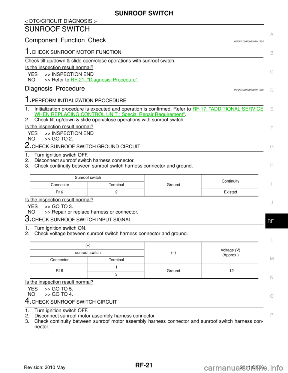
2.CHECK SUNROOF SWITCH GROUND CIRCUIT
1. Turn ignition switch OFF.
2. Disconnect sunroof switch harness connector.
3. Check continuity between sunroof switch harness connector and ground.
Is the inspection result normal?
YES >> GO TO 3.
NO >> Repair or replace harness or connector.
3.CHECK SUNROOF SWITCH INPUT SIGNAL
1. Turn ignition switch ON.
2. Check voltage between sunroof switch harness connector and ground.
Is the inspection result normal?
YES >> GO TO 5.
NO >> GO TO 4.
4.CHECK SUNROOF SWITCH CIRCUIT
1. Turn ignition switch OFF.
2. Disconnect sunroof motor assembly harness connector.
3. Check continuity between sunroof motor assemb ly harness connector and sunroof switch harness con-
nector.
Sunroof switch
GroundContinuity
Connector Terminal
R16 2 Existed
(+) (− ) Voltage (V)
(Approx.)
sunroof switch
Connector Terminal
R16 1
Ground 12
3
Revision: 2010 May2011 QX56
Page 4237 of 5598
SUNROOF DOES NOT OPERATE PROPERLYRF-23
< SYMPTOM DIAGNOSIS >
C
DE
F
G H
I
J
L
M A
B
RF
N
O P
SYMPTOM DIAGNOSIS
SUNROOF DOES NOT OPERATE PROPERLY
DescriptionINFOID:0000000006141238
When auto operation does not operated.
When does not stop fully open or fully closed operation.
Diagnosis ProcedureINFOID:0000000006141239
1.PERFORM INITIALIZATION PROCEDURE
Initialization procedure is executed and operation is confirmed.
Refer to RF-17, "
ADDITIONAL SERVICE WHEN REPLACING CO NTROL UNIT : Special Repair Require-
ment".
Is the inspection result normal?
YES >> GO TO 2.
NO >> Repair or replace the malfunctioning parts.
2.CHECK SUNROOF MOTOR ASSEMBLY POWER SUPPLY AND GROUND CIRCUIT
Check sunroof motor assembly power supply and ground circuit.
Refer to RF-18, "
DiagnosisProcedure".
Is the inspection result normal?
YES >> GO TO 3.
NO >> Repair or replace the malfunctioning parts.
3.CHECK VEHICLE SPEED SIGNAL CIRCUIT
Check vehicle speed signal circuit.
Refer to RF-20, "
DiagnosisProcedure".
Is the inspection result normal?
YES >> GO TO 4.
NO >> Repair or replace the malfunctioning parts.
4.CHECK SUNROOF SWITCH
Check sunroof switch.
Refer to RF-21, "
ComponentFunctionCheck".
Is the inspection result normal?
YES >> GO TO 5.
NO >> Repair or replace the malfunctioning parts.
5.CONFIRM THE OPERATION
Confirm the operation again.
Is the result normal?
YES >> Check intermittent incident. Refer to GI-40, "Intermittent Incident".
NO >> GO TO 1.
Revision: 2010 May2011 QX56
Page 4238 of 5598

RF-24
< SYMPTOM DIAGNOSIS >
SUNROOF DOES NOT OPERATE ANTI-PINCH FUNCTION
SUNROOF DOES NOT OPERATE ANTI-PINCH FUNCTION
Diagnosis ProcedureINFOID:0000000006141240
1.PERFORM INITIALIZATION PROCEDURE
Initialization procedure is exec uted and operation is confirmed.
Refer to RF-17, "
ADDITIONAL SERVICE WHEN REPLACING CO NTROL UNIT : Special Repair Require-
ment".
Is the inspection result normal?
YES >> INSPECTION END
NO >> Replace sunroof motor assembly.
Revision: 2010 May2011 QX56
Page 4240 of 5598
RF-26
< SYMPTOM DIAGNOSIS >
SQUEAK AND RATTLE TROUBLE DIAGNOSES
SQUEAK AND RATTLE TROUBLE DIAGNOSES
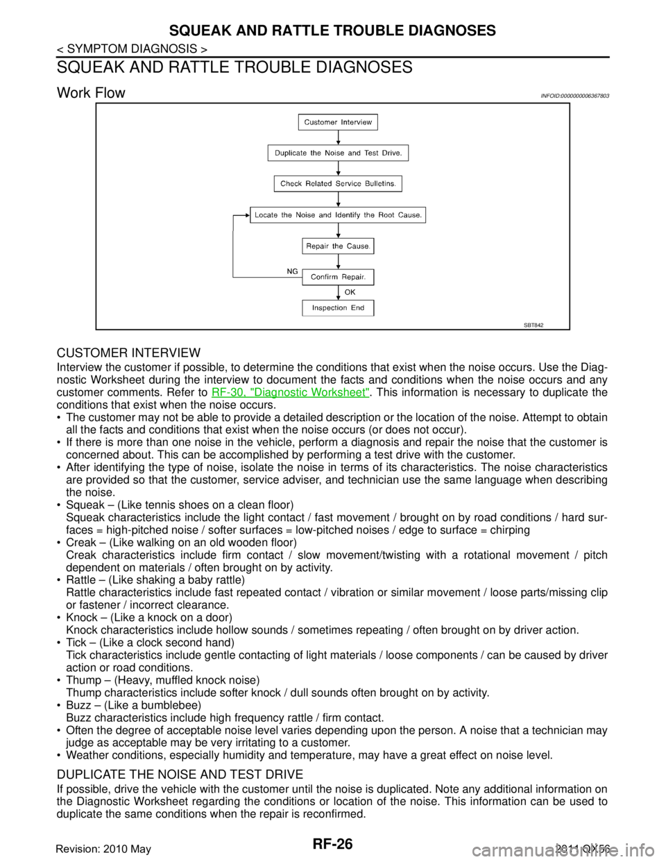
Work FlowINFOID:0000000006367803
CUSTOMER INTERVIEW
Interview the customer if possible, to determine the c onditions that exist when the noise occurs. Use the Diag-
nostic Worksheet during the interview to document the facts and conditions when the noise occurs and any
customer comments. Refer to RF-30, "
Diagnostic Worksheet". This information is necessary to duplicate the
conditions that exist when the noise occurs.
The customer may not be able to provide a detailed description or the location of the noise. Attempt to obtain all the facts and conditions that exist w hen the noise occurs (or does not occur).
If there is more than one noise in the vehicle, perform a diagnosis and repair the noise that the customer is
concerned about. This can be accomplished by per forming a test drive with the customer.
After identifying the type of noise, isolate the noise in terms of its characteristics. The noise characteristics
are provided so that the customer, service advis er, and technician use the same language when describing
the noise.
Squeak – (Like tennis shoes on a clean floor)
Squeak characteristics include the light contact / fast movement / brought on by road conditions / hard sur-
faces = high-pitched noise / softer surfaces = low-pitched noises / edge to surface = chirping
Creak – (Like walking on an old wooden floor)
Creak characteristics include firm contact / slow movement/twisting with a rotational movement / pitch
dependent on materials / often brought on by activity.
Rattle – (Like shaking a baby rattle)
Rattle characteristics include fast repeated contact / vibr ation or similar movement / loose parts/missing clip
or fastener / incorrect clearance.
Knock – (Like a knock on a door)
Knock characteristics include hollow sounds / someti mes repeating / often brought on by driver action.
Tick – (Like a clock second hand) Tick characteristics include gentle contacting of light materials / loose components / can be caused by driver
action or road conditions.
Thump – (Heavy, muffled knock noise) Thump characteristics include softer knock / dull sounds often brought on by activity.
Buzz – (Like a bumblebee)
Buzz characteristics include high frequency rattle / firm contact.
Often the degree of acceptable noise level varies depending upon the person. A noise that a technician may
judge as acceptable may be very irritating to a customer.
Weather conditions, especially humidity and temperat ure, may have a great effect on noise level.
DUPLICATE THE NOISE AND TEST DRIVE
If possible, drive the vehicle with the customer until the noise is duplicated. Note any additional information on
the Diagnostic Worksheet regarding the conditions or lo cation of the noise. This information can be used to
duplicate the same conditions when the repair is reconfirmed.
SBT842
Revision: 2010 May2011 QX56
Page 4241 of 5598
SQUEAK AND RATTLE TROUBLE DIAGNOSESRF-27
< SYMPTOM DIAGNOSIS >
C
DE
F
G H
I
J
L
M A
B
RF
N
O P
If the noise can be duplicated easily during the test drive, to help identify the source of the noise, try to dupli-
cate the noise with the vehicle stopped by doing one or all of the following items:
1) Close a door.
2) Tap or push/pull around the area where the noise appears to be coming from.
3) Rev the engine.
4) Use a floor jack to recreate vehicle “twist”.
5) At idle, apply engine load (electrical load, half-cl utch on M/T models, drive position on A/T models).
6) Raise the vehicle on a hoist and hit a tire with a rubber hammer.
Drive the vehicle and attempt to duplicate the conditions the customer states exist when the noise occurs.
If it is difficult to duplicate the noise, drive the vehicle slowly on an undulating or rough road to stress the vehicle body.
CHECK RELATED SERVICE BULLETINS
After verifying the customer concern or symptom, che ck ASIST for Technical Service Bulletins (TSBs) related
to the concern or symptom.
If a TSB relates to the symptom, follow the procedure to repair the noise.
LOCATE THE NOISE AND IDENTIFY THE ROOT CAUSE
1. Narrow down the noise to a general area. To help pinpoint the source of the noise, use a listening tool
(Chassis ear: J-39570, engine ear, and mechanics stethoscope).
2. Narrow down the noise to a more specific area and identify the cause of the noise by:
Removing the component(s) in the area that is / are suspected to be the cause of the noise.
Do not use too much force when removing clips and fasteners, otherwise clips and fasteners can be broken
or lost during the repair, resulting in the creation of new noise.
Tapping or pushing/pulling the component(s) that is / are suspected to be the cause of the noise.
Do not tap or push/pull the component(s) with excessive force, otherwise the noise is eliminated only tempo-
rarily.
Feeling for a vibration by hand by touching the component(s ) that is / are suspected to be the cause of the
noise.
Placing a piece of paper between components that are suspected to be the cause of the noise.
Looking for loose components and contact marks. Refer to RF-28, "
Inspection Procedure".
REPAIR THE CAUSE
If the cause is a loose component, tighten the component securely.
If the cause is insufficient clearance between components:
- Separate components by repositioning or loosening and retightening the components, if possible.
- Insulate components with a suitable insulator such as urethane pads, foam blocks, felt cloth tape, or ure-
thane tape. A NISSAN Squeak and Rattle Kit (J-43980) is available through the authorized NISSAN Parts
Department.
CAUTION:
Never use excessive force as many components are constructed of plastic and may be damaged.
NOTE:
Always check with the Parts Department for the latest parts information.
The following materials are contained in the NISSA N Squeak and Rattle Kit (J-43980). Each item can be
ordered separately as needed.
URETHANE PADS [1.5 mm (0.059 in) thick]
Insulates connectors, harness, etc.
76268-9E005: 100 ×135 mm (3.937 ×5.315 in)
76884-71L01: 60 ×85 mm (2.362 ×3.346 in)
76884-71L02: 15 ×25 mm (0.591 ×0.984 in)
INSULATOR (Foam blocks)
Insulates components from contact. Can be used to fill space behind a panel.
73982-9E000: 45 mm (1.772 in) thick, 50 ×50 mm (1.969 ×1.969 in)
73982-50Y00: 10 mm (0.394 in) thick, 50 ×50 mm (1.969 ×1.969 in)
INSULATOR (Light foam block)
80845-71L00: 30 mm (1.181 in) thick, 30 ×50 mm (1.181 ×1.969in)
FELT CLOTHTAPE
Used to insulate where movement does not occur. Ideal for instrument panel applications.
68370-4B000: 15 ×25 mm (0.591 ×0.984 in) pad
68239-13E00: 5 mm (0.197 in) wide tape roll
Revision: 2010 May2011 QX56