2011 INFINITI QX56 warning
[x] Cancel search: warningPage 1741 of 5598
AUTOMATIC BACK DOOR WARNING DOES NOT OPERATE
DLK-205
< SYMPTOM DIAGNOSIS >
C
D E
F
G H
I
J
L
M A
B
DLK
N
O P
Check hazard and horn reminder function.
Is the inspection result normal?
YES >> GO TO 5.
NO >> Refer to DLK-183, "
Diagnosis Procedure".
5.REPLACE AUTOMATIC BACK DOOR CONTROL MODULE
1. Replace automatic back door control module. Refer to DLK-262, "
Removal and Installation".
2. Confirm the operation after replacement.
Is the result normal?
YES >> INSPECTION END
NO >> Check intermittent incident. Refer to GI-40, "
Intermittent Incident".
Revision: 2010 May2011 QX56
Page 1751 of 5598
HOOD
DLK-215
< REMOVAL AND INSTALLATION >
C
D E
F
G H
I
J
L
M A
B
DLK
N
O P
REMOVAL AND INSTALLATION
HOOD
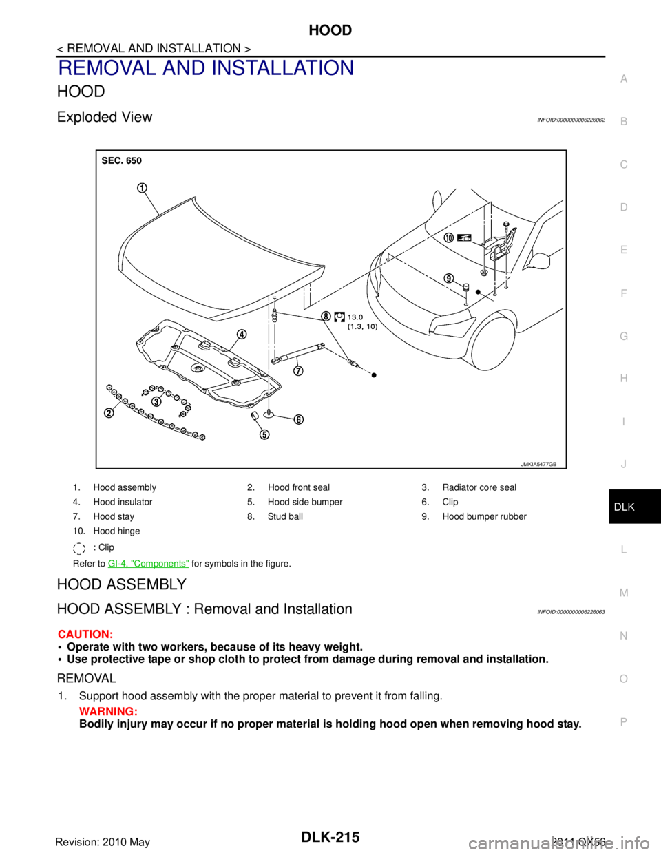
Exploded ViewINFOID:0000000006226062
HOOD ASSEMBLY
HOOD ASSEMBLY : Removal and InstallationINFOID:0000000006226063
CAUTION:
Operate with two workers, because of its heavy weight.
Use protective tape or shop cloth to protect from damage during removal and installation.
REMOVAL
1. Support hood assembly with the proper material to prevent it from falling.
WARNING:
Bodily injury may occur if no proper material is holding hood open when removing hood stay.
1. Hood assembly 2. Hood front seal 3. Radiator core seal
4. Hood insulator 5. Hood side bumper 6. Clip
7. Hood stay 8. Stud ball 9. Hood bumper rubber
10. Hood hinge
: Clip
Refer to GI-4, "
Components" for symbols in the figure.
JMKIA5477GB
Revision: 2010 May2011 QX56
Page 1754 of 5598
DLK-218
< REMOVAL AND INSTALLATION >
HOOD
After installation, apply touch-up paint (the body color) onto the head of hood hinge mountingbolts and nuts.
HOOD HINGE
HOOD HINGE : Removal and InstallationINFOID:0000000006226065
REMOVAL
1. Remove hood assembly. Refer to DLK-215, "HOOD ASSEMBLY : Removal and Installation".
2. Remove front fender cover. Refer to EXT-21, "
Exploded View".
3. Remove front fender mounting bolt. DLK-222, "
Exploded View".
4. Remove hood hinge mounting bolts, and then remove hood hinge.
INSTALLATION
Note the following items, and install in the reverse order of removal.
CAUTION:
Before installation of hood hing e, apply anticorrosive agent onto the mounting surface of the vehicle
body.
After installation, apply touch-up paint (the body color) onto the head of the hinge mounting bolts
and nuts.
After installation, perform hood fitting adjustment. Refer to DLK-216, "
HOOD ASSEMBLY : Adjust-
ment".
HOOD STAY
HOOD STAY : Removal and InstallationINFOID:0000000006226066
REMOVAL
1. Support hood assembly with a proper material to prevent it from falling.
WARNING:
Bodily injury may occur if no proper material is holding the hood open when removing the hood
stay.
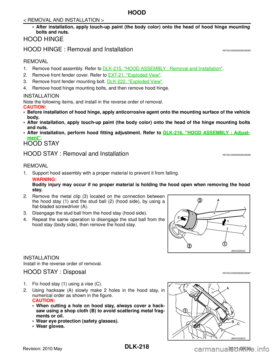
2. Remove the metal clip (3) located on the connection between the hood stay (1) and the stud ball (2) (hood side), by using a
flat-bladed screwdriver (A).
3. Disengage the stud ball from the hood stay (hood side).
4. Repeat the same operation to disengage the stud ball from the hood stay (body side), then remove the hood stay.
INSTALLATION
Install in the reverse order of removal.
HOOD STAY : Disposal INFOID:0000000006226067
1. Fix hood stay (1) using a vise (C).
2. Using hacksaw (A) slowly make 2 holes in the hood stay, innumerical order as shown in the figure.
CAUTION:
When cutting a hole on hood stay, always cover a hack-saw using a shop cloth (B) to avoid scattering metal frag-
ments or oil.
Wear eye protection (safety glasses).
Wear gloves.
JMKIA2255ZZ
JMKIA3336ZZ
Revision: 2010 May2011 QX56
Page 1769 of 5598
BACK DOORDLK-233
< REMOVAL AND INSTALLATION >
C
DE
F
G H
I
J
L
M A
B
DLK
N
O P
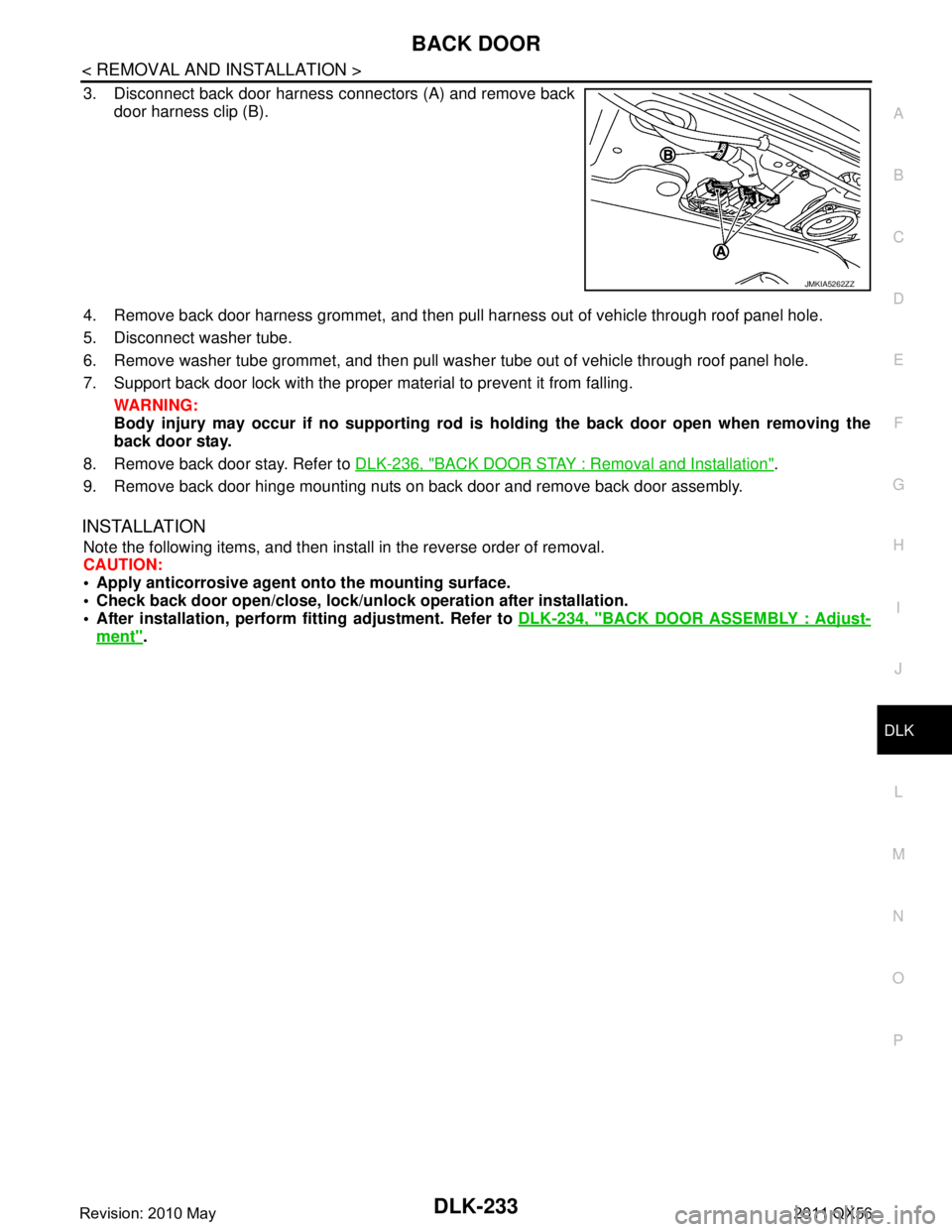
3. Disconnect back door harness connectors (A) and remove back door harness clip (B).
4. Remove back door harness grommet, and then pull harness out of vehicle through roof panel hole.
5. Disconnect washer tube.
6. Remove washer tube grommet, and then pull was her tube out of vehicle through roof panel hole.
7. Support back door lock with the proper material to prevent it from falling. WARNING:
Body injury may occur if no sup porting rod is holding the back door open when removing the
back door stay.
8. Remove back door stay. Refer to DLK-236, "
BACK DOOR STAY : Removal and Installation".
9. Remove back door hinge mounting nuts on back door and remove back door assembly.
INSTALLATION
Note the following items, and then install in the reverse order of removal.
CAUTION:
Apply anticorrosive agen t onto the mounting surface.
Check back door open/close, lock/un lock operation after installation.
After installation, perform fitting adjustment. Refer to DLK-234, "
BACK DOOR ASSEMBLY : Adjust-
ment".
JMKIA5262ZZ
Revision: 2010 May2011 QX56
Page 1772 of 5598
DLK-236
< REMOVAL AND INSTALLATION >
BACK DOOR
BACK DOOR HINGE
BACK DOOR HINGE : Removal and InstallationINFOID:0000000006226090
CAUTION:
Operate with two workers, because of its heavy weight.
Use protective tape or cloth to protect fr om damage during remove and installation.
REMOVAL
1. Remove back door assembly. Refer to DLK-232, "BACK DOOR ASSEMBLY : Removal and Installation".
2. Remove back door hinge mounting nuts (body side), and then remove back door hinge.
INSTALLATION
Note the following items, and then install in the reverse order of removal.
CAUTION:
Apply anticorrosive agent onto the mounting surface.
Check back door open/close op eration after installation.
Check back door hinge ro tating part for poor lubricatio n. If necessary, apply body grease.
When removing and installing back door assembly, perform the fitting adjustment. Refer to DLK-234,
"BACK DOOR ASSEMBLY : Adjustment".
After installation, apply touch-up paint (the body color) onto the head of back door hinge mounting
nuts.
BACK DOOR STAY
BACK DOOR STAY : Removal and InstallationINFOID:0000000006226091
REMOVAL
1. Support back door lock with the proper material to prevent it from falling.
WARNING:
Body injury may occur if no su pporting rod is holding the back door op en when removing the
back door stay.
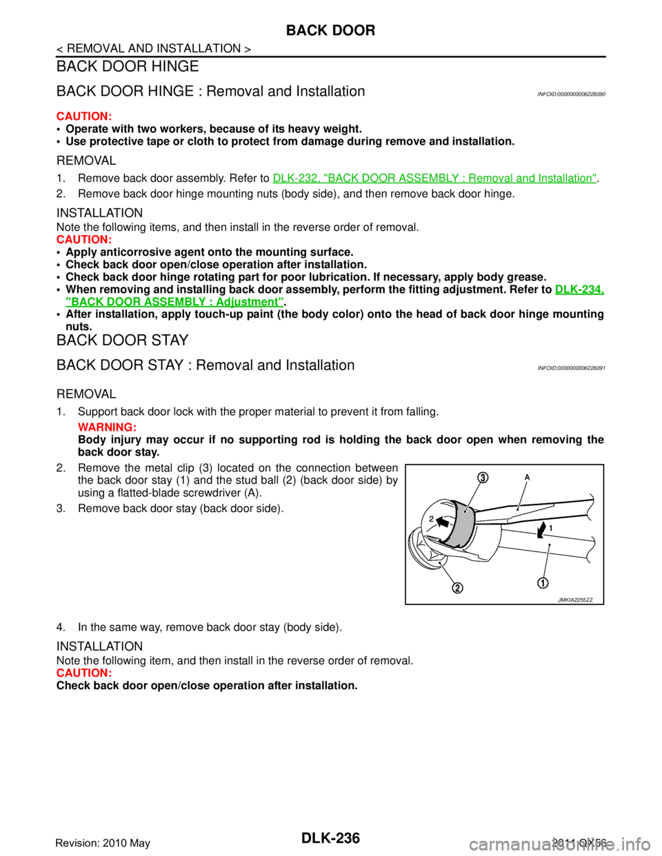
2. Remove the metal clip (3) located on the connection between the back door stay (1) and the stud ball (2) (back door side) by
using a flatted-blade screwdriver (A).
3. Remove back door stay (back door side).
4. In the same way, remove back door stay (body side).
INSTALLATION
Note the following item, and then install in the reverse order of removal.
CAUTION:
Check back door open/close ope ration after installation.
JMKIA2255ZZ
Revision: 2010 May2011 QX56
Page 1794 of 5598

DLK-258
< REMOVAL AND INSTALLATION >
INTELLIGENT KEY WARNING BUZZER
INTELLIGENT KEY WARNING BUZZER
Removal and InstallationINFOID:0000000006226125
REMOVAL
Remove the Intelligent Key warning buzzer mounting bolt, and then remove the Intelligent Key warning
buzzer.
INSTALLATION
Install in the reverse order of removal.
Revision: 2010 May2011 QX56
Page 1799 of 5598
AUTOMATIC BACK DOOR WARNING BUZZERDLK-263
< REMOVAL AND INSTALLATION >
C
DE
F
G H
I
J
L
M A
B
DLK
N
O P
AUTOMATIC BACK DOOR WARNING BUZZER
Removal and InstallationINFOID:0000000006226130
REMOVAL
1. Remove the back door finisher inner. Refer to INT-39, "Removal and Installation".
2. Remove the automatic back door warning buzzer mounting nut, and then remove the automatic back door
warning buzzer.
INSTALLATION
Install in the reverse order of removal.
Revision: 2010 May2011 QX56
Page 1805 of 5598
DLN-3
CEF
G H
I
J
K L
M A
B
DLN
N
O P
U1000 CAN COMM CIRCUIT ......................... ....91
Description .......................................................... ....91
DTC Logic ...............................................................91
Diagnosis Procedure ...............................................91
U1010 CONTROL UNIT (CAN) ..........................92
Description .......................................................... ....92
DTC Logic ...............................................................92
Diagnosis Procedure ...............................................92
POWER SUPPLY AND GROUND CIRCUIT ......93
Description .......................................................... ....93
Diagnosis Procedure ...............................................93
4WD WARNING LAMP ......................................97
Component Function Check ................................ ....97
Diagnosis Procedure ...............................................97
4WD INDICATOR LAMP ....................................98
Component Function Check ................................ ....98
Diagnosis Procedure ...............................................98
SYMPTOM DIAGNOSIS ..............................99
HEAVY TIGHT-CORNER BRAKING SYMP-
TOM OCCURS . .............................................. ....
99
Description .......................................................... ....99
Diagnosis Procedure ...............................................99
4WD MODE DOES NOT CHANGE ..................100
Description .......................................................... ..100
Diagnosis Procedure .............................................100
4WD MODE INDICATOR LAMP CONTINUES
BLINKING .........................................................
101
Description .......................................................... ..101
Diagnosis Procedure .............................................101
4WD WARNING LAMP BLINKS QUICKLY .....102
Description .......................................................... ..102
4WD WARNING LAMP BLINKS SLOWLY .....103
Description .......................................................... ..103
Diagnosis Procedure .............................................103
INFORMATION DISPLAY IS NOT DIS-
PLAYED ...........................................................
104
Description .......................................................... ..104
Diagnosis Procedure .............................................104
NOISE, VIBRATION AND HARSHNESS
(NVH) TROUBLESHOOTING ..........................
105
NVH Troubleshooting Chart ................................ ..105
PERIODIC MAINTENANCE .......................106
TRANSFER FLUID ......................................... ..106
Inspection ............................................................ ..106
Draining .................................................................106
Refilling .................................................................106
REMOVAL AND INSTALLATION .............107
TRANSFER CONTROL UNIT .........................107
Removal and Installation ..................................... ..107
4WD MODE SWITCH ......................................108
Removal and Installation .......................................108
FRONT OIL SEAL ...........................................109
Exploded View .......................................................109
Removal and Installation .......................................109
REAR OIL SEAL .............................................111
Exploded View .......................................................111
Removal and Installation .......................................111
Adjustment .............................................................112
TRANSFER CONTROL ACTUATOR .............114
Exploded View .......................................................114
Removal and Installation .......................................114
Inspection ..............................................................114
TRANSFER HI-LO POSITION SENSOR ........116
Exploded View .......................................................116
Removal and Installation .......................................116
Inspection ..............................................................116
TRANSFER ROTARY POSITION SENSOR ...117
Exploded View .......................................................117
Removal and Installation .......................................117
Inspection ..............................................................118
TRANSFER LOCK POSITION SENSOR ........119
Exploded View .......................................................119
Removal and Installation .......................................119
Inspection ..............................................................119
TRANSFER FLUID TEMPERATURE SEN-
SOR .................................................................
120
Exploded View .......................................................120
Removal and Installation .......................................120
Inspection ..............................................................120
UNIT REMOVAL AND INSTALLATION ....121
TRANSFER ASSEMBLY ................................121
Exploded View ..................................................... ..121
Removal and Installation .......................................121
INPUT OIL SEAL ............................................123
Exploded View .......................................................123
Removal and Installation .......................................123
SERVICE DATA AND SPECIFICATIONS
(SDS) ............... ...........................................
124
SERVICE DATA AND SPECIFICATIONS
(SDS) ...............................................................
124
General Specifications ......................................... ..124
FRONT PROPELLER SHAFT: 2F P15
PREPARATION ........ .................................
125
PREPARATION ...............................................125
Revision: 2010 May2011 QX56