2011 INFINITI QX56 warning
[x] Cancel search: warningPage 2202 of 5598
![INFINITI QX56 2011 Factory Service Manual
EC-178
< DTC/CIRCUIT DIAGNOSIS >[VK56VD]
P0011, P0021 IVT CONTROL
CAUTION:
Always drive at a safe speed.
3. Check 1st trip DTC.
WITH GST
Follow the procedure “With CONSULT-III” above.
Is 1st tri INFINITI QX56 2011 Factory Service Manual
EC-178
< DTC/CIRCUIT DIAGNOSIS >[VK56VD]
P0011, P0021 IVT CONTROL
CAUTION:
Always drive at a safe speed.
3. Check 1st trip DTC.
WITH GST
Follow the procedure “With CONSULT-III” above.
Is 1st tri](/manual-img/42/57033/w960_57033-2201.png)
EC-178
< DTC/CIRCUIT DIAGNOSIS >[VK56VD]
P0011, P0021 IVT CONTROL
CAUTION:
Always drive at a safe speed.
3. Check 1st trip DTC.
WITH GST
Follow the procedure “With CONSULT-III” above.
Is 1st trip DTC detected?
YES >> Go to EC-178, "Diagnosis Procedure".
NO >> INSPECTION END
Diagnosis ProcedureINFOID:0000000006217773
1.CHECK OIL PRESSURE WARNING LAMP
1. Start engine.
2. Check that oil pressure warning lamp is not illuminated.
Is oil pressure warning lamp illuminated?
YES >> Go to LU-7, "Inspection".
NO >> GO TO 2.
2.CHECK INTAKE VALVE TIMING CONTROL SOLENOID VALVE
Refer to EC-179, "
Component Inspection (Intake Valve Timing Control Solenoid Valve)".
Is the inspection result normal?
YES >> GO TO 3.
NO >> Replace malfunctioning intake valve timing control solenoid valve. Refer to EM-61, "
Exploded
View".
3.CHECK CRANKSHAFT POSITION SENSOR
Refer to EC-301, "
Component Inspection (Crankshaft Position Sensor)".
Is the inspection result normal?
YES >> GO TO 4.
NO >> Replace crankshaft position sensor. Refer to EM-106, "
Exploded View".
4.CHECK CAMSHAFT POSITION SENSOR
Refer to EC-306, "
Component Inspection (Camshaft Position Sensor)".
Is the inspection result normal?
YES >> GO TO 5.
NO >> Replace malfunctioning camshaft position sensor. Refer to EM-106, "
Exploded View".
5.CHECK CAMSHAFT (INTAKE)
Check the following.
Selector lever 1st or 2nd position
Driving location uphill Driving vehicle uphill
(Increased engine load will help maintain the driving
conditions required for this test.)
PBIA8559J
Revision: 2010 May2011 QX56
Page 2377 of 5598
![INFINITI QX56 2011 Factory Service Manual
P0461 FUEL LEVEL SENSOREC-353
< DTC/CIRCUIT DIAGNOSIS > [VK56VD]
C
D
E
F
G H
I
J
K L
M A
EC
NP
O
P0461 FUEL LEVEL SENSOR
DTC LogicINFOID:0000000006288330
DTC DETECTION LOGIC
NOTE:
If DTC P0461 is d INFINITI QX56 2011 Factory Service Manual
P0461 FUEL LEVEL SENSOREC-353
< DTC/CIRCUIT DIAGNOSIS > [VK56VD]
C
D
E
F
G H
I
J
K L
M A
EC
NP
O
P0461 FUEL LEVEL SENSOR
DTC LogicINFOID:0000000006288330
DTC DETECTION LOGIC
NOTE:
If DTC P0461 is d](/manual-img/42/57033/w960_57033-2376.png)
P0461 FUEL LEVEL SENSOREC-353
< DTC/CIRCUIT DIAGNOSIS > [VK56VD]
C
D
E
F
G H
I
J
K L
M A
EC
NP
O
P0461 FUEL LEVEL SENSOR
DTC LogicINFOID:0000000006288330
DTC DETECTION LOGIC
NOTE:
If DTC P0461 is displayed with DTC UXXXX, first perform the tr ouble diagnosis for DTC UXXXX.
If DTC P0461 is displayed with DT C P0607, first perform the trouble diagnosis for DTC P0607. Refer
to EC-378, "
DTC Logic".
Driving long distances naturally affect fuel gauge level.
This diagnosis detects the fuel gauge malfunction of the gauge not moving even after a long distance has
been driven.
DTC CONFIRMATION PROCEDURE
1.PERFORM COMPONENT FUNCTION CHECK
Perform Component Function Check. Refer to EC-353, "
Component Function Check".
Use component function check to check the overall function of the fuel level sensor. During this check, a 1st
trip DTC might not be confirmed.
Is the inspection result normal?
YES >> INSPECTION END
NO >> Proceed to EC-354, "
Diagnosis Procedure".
Component Function CheckINFOID:0000000006288331
1.PRECONDITIONING
WARNING:
When performing the following procedure, alw ays observe the handling of the fuel. Refer to FL-2,
"General Precautions".
TESTING CONDITION:
Before starting component function check, preparation of draining fuel and refilling fuel is required.
>> GO TO 2.
2.PERFORM COMPONENT FUNCTION CHECK
NOTE:
Start from step 8, if it is possible to confirm that the fuel cannot be drained by 30 (7-7/8 US gal, 6-5/8
Imp gal) in advance.
1. Prepare a fuel container and a spare hose.
2. Release fuel pressure from fuel line. Refer to EC-153, "
Work Procedure".
3. Remove the fuel feed hose on the fuel level sensor unit. Refer to FL-5, "
Removal and Installation".
4. Connect a spare fuel hose where the fuel feed hose was removed.
5. Turn ignition switch ON.
6. Drain fuel by 30 (7-7/8 US gal, 6-5/8 Imp gal) from the fuel tank using proper equipment.
7. Confirm that the fuel gauge indication varies.
8. Fill fuel into the fuel tank for 30 (7-7/8 US gal, 6-5/8 Imp gal).
9. Confirm that the fuel gauge indication varies.
Is the inspection result normal?
DTC No. Trouble diagnosis name
(Trouble diagnosis content) DTC detecting condition Possible cause
P0461 FUEL LEVEL SENSOR
(Fuel level sensor circuit
range/performance) The output signal of the fuel level sensor
does not change within the specified
range even though the vehicle has been
driven a long distance. Harness or connectors
(The CAN communication line is open or short-
ed)
Harness or connectors (The sensor circuit is open or shorted)
Combination meter
Fuel level sensor
Revision: 2010 May2011 QX56
Page 2389 of 5598
![INFINITI QX56 2011 Factory Service Manual
P0524 ENGINE OIL PRESSUREEC-365
< DTC/CIRCUIT DIAGNOSIS > [VK56VD]
C
D
E
F
G H
I
J
K L
M A
EC
NP
O
NO >> INSPECTION END
Diagnosis ProcedureINFOID:0000000006288343
1.CHECK OIL PRESSURE WARNING LAMP
1. INFINITI QX56 2011 Factory Service Manual
P0524 ENGINE OIL PRESSUREEC-365
< DTC/CIRCUIT DIAGNOSIS > [VK56VD]
C
D
E
F
G H
I
J
K L
M A
EC
NP
O
NO >> INSPECTION END
Diagnosis ProcedureINFOID:0000000006288343
1.CHECK OIL PRESSURE WARNING LAMP
1.](/manual-img/42/57033/w960_57033-2388.png)
P0524 ENGINE OIL PRESSUREEC-365
< DTC/CIRCUIT DIAGNOSIS > [VK56VD]
C
D
E
F
G H
I
J
K L
M A
EC
NP
O
NO >> INSPECTION END
Diagnosis ProcedureINFOID:0000000006288343
1.CHECK OIL PRESSURE WARNING LAMP
1. Start engine.
2. Check oil pressure warning lamp and confirm it is not illumi- nated.
Is oil pressure warning lamp illuminated?
YES >> Proceed to LU-7, "Inspection".
NO >> GO TO 2.
2.CHECK INTAKE VALVE TIMING CONTROL SOLENOID VALVE
Refer to EC-179, "
Component Inspection (Intake Valve Timing Control Solenoid Valve)".
Is the inspection result normal?
YES >> GO TO 3.
NO >> Replace malfunctioning intake valve timing control solenoid valve.
3.CHECK CRANKSHAFT POSITION SENSOR
Refer to EC-301, "
Component Inspection (Crankshaft Position Sensor)".
Is the inspection result normal?
YES >> GO TO 4.
NO >> Replace crankshaft position sensor.
4.CHECK CAMSHAFT PO SITION SENSOR
Refer to EC-306, "
Component Inspection (Camshaft Position Sensor)".
Is the inspection result normal?
YES >> GO TO 5.
NO >> Replace malfunctioning camshaft position sensor.
5.CHECK CAMSHAFT SPROCKET (SIGNAL PLATE)
Check the following.
Accumulation of debris to the signal plate of camshaft sprocket (INT)
Chipping signal plate of camshaft sprocket (INT)
Is the inspection result normal?
YES >> GO TO 6.
NO >> Remove debris and clean the signal plate of camshaft sprocket (INT) or replace camshaft sprocket (INT).
Refer to EM-61, "
Exploded View".
6.CHECK TIMING CHAIN INSTALLATION
Check service records for any recent repairs that may cause timing chain misaligned.
Are there any service records that may cause timing chain misaligned?
YES >> Check timing chain installation. Refer to EM-61, "Exploded View".
NO >> GO TO 7.
7.CHECK LUBRICATION CIRCUIT
Perform “Inspection of Camshaft Sprocket (INT) Oil Groove”. Refer to LU-7, "
Inspection".
PBIA8559J
JMBIA0962ZZ
Revision: 2010 May2011 QX56
Page 2424 of 5598
![INFINITI QX56 2011 Factory Service Manual
EC-400
< DTC/CIRCUIT DIAGNOSIS >[VK56VD]
P1217 ENGINE OVER TEMPERATURE
P1217 ENGINE OVER TEMPERATURE
DTC LogicINFOID:0000000006217909
DTC DETECTION LOGIC
NOTE:
If DTC P1217 is displayed with DTC UX INFINITI QX56 2011 Factory Service Manual
EC-400
< DTC/CIRCUIT DIAGNOSIS >[VK56VD]
P1217 ENGINE OVER TEMPERATURE
P1217 ENGINE OVER TEMPERATURE
DTC LogicINFOID:0000000006217909
DTC DETECTION LOGIC
NOTE:
If DTC P1217 is displayed with DTC UX](/manual-img/42/57033/w960_57033-2423.png)
EC-400
< DTC/CIRCUIT DIAGNOSIS >[VK56VD]
P1217 ENGINE OVER TEMPERATURE
P1217 ENGINE OVER TEMPERATURE
DTC LogicINFOID:0000000006217909
DTC DETECTION LOGIC
NOTE:
If DTC P1217 is displayed with DTC UXXXX, perform the trouble diagnosis for DTC UXXXX.
If DTC P1217 is displayed with DTC P0607, perfo rm the trouble diagnosis for DTC P0607. Refer to
EC-378, "
DTC Logic".
If DTC P1217 is displayed with DTC P0527, perfo rm the trouble diagnosis for DTC P0527. Refer to
EC-367, "
DTC Logic".
If the cooling fan or any of other components in the cooling system has a malfunction, engine coolant temper-
ature increases.
When the engine coolant temperature reaches an abnorma lly high temperature condition, a malfunction is
indicated.
CAUTION:
When a malfunction is indicated, al ways replace the coolant. Refer to CO-8, "
Draining" and CO-9,
"Refilling". Also, replace the engine oil. Refer to LU-8, "Draining" and LU-8, "Refilling".
1. Fill radiator with coolant up to specified level with a filling speed of 2 liters per minute. Always use
coolant with the proper mixture ratio. Refer to MA-11, "
Anti-Freeze Coolant Mixture Ratio".
2. After refilling coolant, run engine to en sure that no water-flow noise is emitted.
DTC CONFIRMATION PROCEDURE
1.PERFORM COMPONENT FUNCTION CHECK
Perform component function check. Refer to EC-400, "
Component Function Check".
NOTE:
Use component function check to check the overall functi on of the cooling fan. During this check, a DTC might
not be confirmed.
Is the inspection result normal?
YES >> INSPECTION END
NO >> Go to EC-401, "
Diagnosis Procedure".
Component Function CheckINFOID:0000000006217910
1.PERFORM COMPONENT FUNCTION CHECK-I
WARNING:
Never remove the reservoir tank cap when the engi ne is hot. Serious burns could be caused by high
pressure fluid escaping from the radiator.
Wrap a thick cloth around cap. Carefully remove the cap by turning it a quarter turn to allow built-up
pressure to escape. Then turn the cap all the way off.
DTC No. Trouble diagnosis name DTC detecting condition Possible cause
P1217 Engine over temperature
(Overheat) Cooling fan does not operate properly
(Overheat).
Cooling fan system does not operate properly (Overheat).
Engine coolant is not within the specified quantity. Harness or connectors
(The cooling fan circuit is open or shorted.)
IPDM E/R
Electrically-controlled cooling fan coupling
Cooling fan speed sensor
Radiator hose
Radiator
Reservoir tank cap
Water pump
Thermostat
Revision: 2010 May2011 QX56
Page 2565 of 5598

PRECAUTIONSEM-3
< PRECAUTION >
C
DE
F
G H
I
J
K L
M A
EM
NP
O
PRECAUTION
PRECAUTIONS
Precaution for Procedur
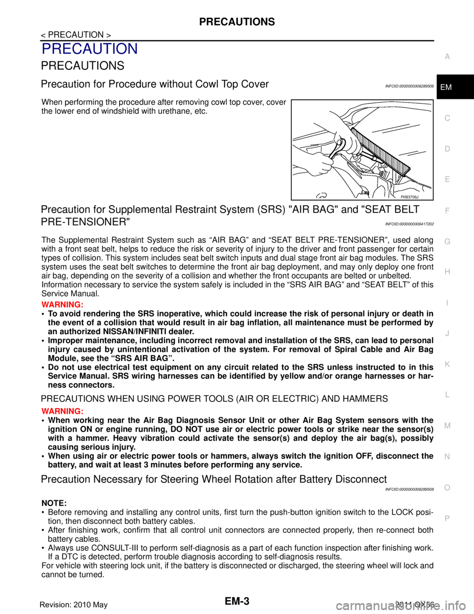
e without Cowl Top CoverINFOID:0000000006289506
When performing the procedure after removing cowl top cover, cover
the lower end of windshield with urethane, etc.
Precaution for Supplemental Restraint System (SRS) "AIR BAG" and "SEAT BELT
PRE-TENSIONER"
INFOID:0000000006417202
The Supplemental Restraint System such as “A IR BAG” and “SEAT BELT PRE-TENSIONER”, used along
with a front seat belt, helps to reduce the risk or severi ty of injury to the driver and front passenger for certain
types of collision. This system includes seat belt switch inputs and dual stage front air bag modules. The SRS
system uses the seat belt switches to determine the front air bag deployment, and may only deploy one front
air bag, depending on the severity of a collision and whether the front occupants are belted or unbelted.
Information necessary to service the system safely is included in the “SRS AIR BAG” and “SEAT BELT” of this
Service Manual.
WARNING:
• To avoid rendering the SRS inoper ative, which could increase the risk of personal injury or death in
the event of a collision that would result in air ba g inflation, all maintenance must be performed by
an authorized NISSAN/INFINITI dealer.
Improper maintenance, including in correct removal and installation of the SRS, can lead to personal
injury caused by unintentional act ivation of the system. For removal of Spiral Cable and Air Bag
Module, see the “SRS AIR BAG”.
Do not use electrical test equipm ent on any circuit related to the SRS unless instructed to in this
Service Manual. SRS wiring harnesses can be identi fied by yellow and/or orange harnesses or har-
ness connectors.
PRECAUTIONS WHEN USING POWER TOOLS (AIR OR ELECTRIC) AND HAMMERS
WARNING:
When working near the Air Bag Diagnosis Sensor Unit or other Air Bag System sensors with the
ignition ON or engine running, DO NOT use air or electric power tools or strike near the sensor(s)
with a hammer. Heavy vibration could activate the sensor(s) and deploy the air bag(s), possibly
causing serious injury.
When using air or electric power tools or hammers , always switch the ignition OFF, disconnect the
battery, and wait at least 3 minutes before performing any service.
Precaution Necessary for Steering Wh eel Rotation after Battery Disconnect
INFOID:0000000006289508
NOTE:
Before removing and installing any control units, first tu rn the push-button ignition switch to the LOCK posi-
tion, then disconnect both battery cables.
After finishing work, confirm that all control unit connectors are connected properly, then re-connect both
battery cables.
Always use CONSULT-III to perform self-diagnosis as a part of each function inspection after finishing work.
If a DTC is detected, perform trouble diagnos is according to self-diagnosis results.
For vehicle with steering lock unit, if the battery is disconnected or discharged, the steering wheel will lock and
cannot be turned.
PIIB3706J
Revision: 2010 May2011 QX56
Page 2582 of 5598

EM-20
< PERIODIC MAINTENANCE >
DRIVE BELTS
PERIODIC MAINTENANCE
DRIVE BELTS
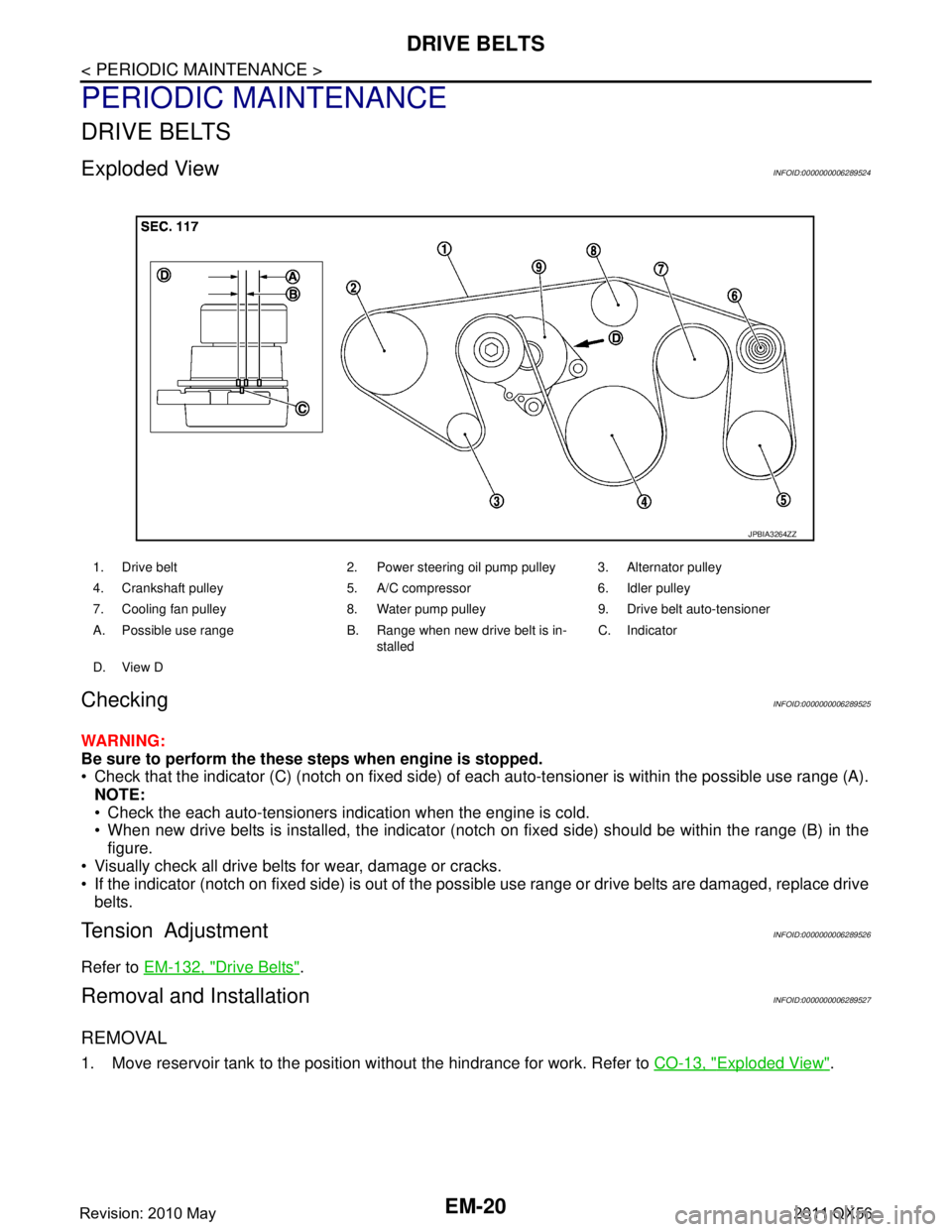
Exploded ViewINFOID:0000000006289524
CheckingINFOID:0000000006289525
WARNING:
Be sure to perform the these steps when engine is stopped.
Check that the indicator (C) (notch on fixed side) of each auto-tensioner is within the possible use range (A).
NOTE:
Check the each auto-tensioners indication when the engine is cold.
When new drive belts is installed, the indicator (notch on fixed side) should be within the range (B) in the\
figure.
Visually check all drive belts for wear, damage or cracks.
If the indicator (notch on fixed side) is out of the possible use range or drive belts are damaged, replace drive
belts.
Tension AdjustmentINFOID:0000000006289526
Refer to EM-132, "Drive Belts".
Removal and InstallationINFOID:0000000006289527
REMOVAL
1. Move reservoir tank to the position without the hindrance for work. Refer to CO-13, "Exploded View".
1. Drive belt 2. Power steering oil pump pulley 3. Alternator pulley
4. Crankshaft pulley 5. A/C compressor 6. Idler pulley
7. Cooling fan pulley 8. Water pump pulley 9. Drive belt auto-tensioner
A. Possible use range B. Range when new drive belt is in-
stalledC. Indicator
D. View D
JPBIA3264ZZ
Revision: 2010 May2011 QX56
Page 2592 of 5598

EM-30
< REMOVAL AND INSTALLATION >
INTAKE MANIFOLD
INTAKE MANIFOLD
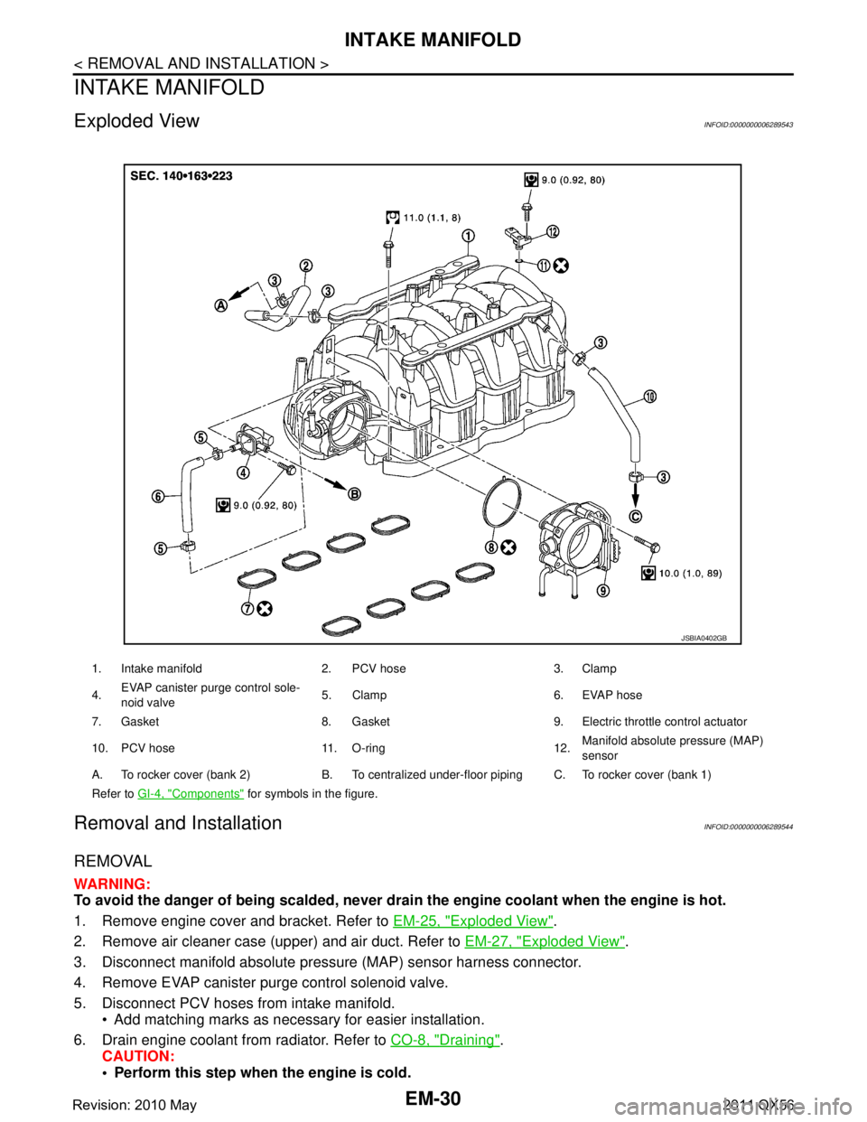
Exploded ViewINFOID:0000000006289543
Removal and InstallationINFOID:0000000006289544
REMOVAL
WARNING:
To avoid the danger of being scalded, never drain the engine coolant when the engine is hot.
1. Remove engine cover and bracket. Refer to EM-25, "
Exploded View".
2. Remove air cleaner case (upper) and air duct. Refer to EM-27, "
Exploded View".
3. Disconnect manifold absolute pressu re (MAP) sensor harness connector.
4. Remove EVAP canister purge control solenoid valve.
5. Disconnect PCV hoses from intake manifold. Add matching marks as necessary for easier installation.
6. Drain engine coolant from radiator. Refer to CO-8, "
Draining".
CAUTION:
Perform this step when the engine is cold.
1. Intake manifold 2. PCV hose 3. Clamp
4. EVAP canister purge control sole-
noid valve 5. Clamp 6. EVAP hose
7. Gasket 8. Gasket 9. Electric throttle control actuator
10. PCV hose 11. O-ring 12. Manifold absolute pressure (MAP)
sensor
A. To rocker cover (bank 2) B. To centralized under-floor piping C. To rocker cover (bank 1)
Refer to GI-4, "
Components" for symbols in the figure.
JSBIA0402GB
Revision: 2010 May2011 QX56
Page 2602 of 5598

EM-40
< REMOVAL AND INSTALLATION >
EXHAUST MANIFOLD AND THREE WAY CATALYST
EXHAUST MANIFOLD AND THREE WAY CATALYST
Exploded ViewINFOID:0000000006289550
Removal and InstallationINFOID:0000000006289551
REMOVAL
WARNING:
Perform the work when the exhaust and cooling system have cooled sufficiently.
1. Drain engine coolant from radiator. Refer to CO-8, "
Draining".
CAUTION:
Perform this step when the engine is cold.
Never spill engine coolant on drive belt.
2. Remove reservoir tank. Refer to CO-13, "
Exploded View".
3. Remove drive belt. Refer to EM-20, "
Removal and Installation".
4. Remove power steering oil pump. Refer to ST-48, "
Exploded View".
5. Remove radiator. Refer to CO-13, "
Exploded View".
6. Remove front under cover. Refer to EXT-25, "
Exploded View".
7. Remove front wheels and tires. Refer to WT-64, "
Exploded View".
8. Remove A/C compressor. Refer to HA-30, "
Exploded View".
9. Remove alternator and alternator bracket. Refer to CHG-25, "
Exploded View".
10. Remove exhaust front tube (bank 1 and bank 2). Refer to EX-5, "
Exploded View".
1. Air fuel ratio sensor 1 (bank 2) 2. Exhaust manifold cover (bank 2) 3. Exhaust manifold and three way cat-
alyst (bank 2)
4. Gasket 5. Exhaust manifold and three way cat-
alyst (bank 1)6. Exhaust manifold cover (bank 1)
7. Air fuel ratio sensor 1 (bank 1)
Refer to GI-4, "
Components" for symbols in the figure.
JSBIA0389GB
Revision: 2010 May2011 QX56