Page 1581 of 5598

DIAGNOSIS SYSTEM (AUTOMATIC BACK DOOR CONTROL UNIT)
DLK-45
< SYSTEM DESCRIPTION >
C
D E
F
G H
I
J
L
M A
B
DLK
N
O P
DIAGNOSIS SYSTEM (AUTOMATIC BACK DOOR CONTROL UNIT)
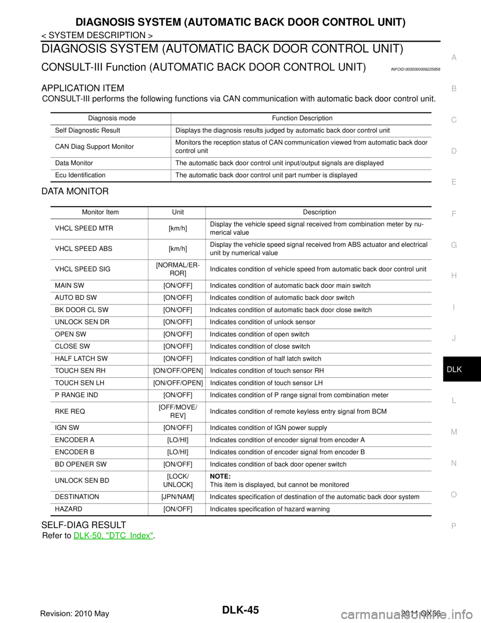
CONSULT-III Function (AUTOMATIC BACK DOOR CONTROL UNIT)INFOID:0000000006225858
APPLICATION ITEM
CONSULT-III performs the following functions via CA N communication with automatic back door control unit.
DATA MONITOR
SELF-DIAG RESULT
Refer to DLK-50, "DTCIndex".
Diagnosis mode Function Description
Self Diagnostic Result Displays the diagnosis results judged by automatic back door control unit
CAN Diag Support Monitor Monitors the reception status of CAN communication viewed from automatic back door
control unit
Data Monitor The automatic back door control unit input/output signals are displayed
Ecu Identification The automatic back door control unit part number is displayed
Monitor Item Unit Description
VHCL SPEED MTR [km/h] Display the vehicle speed signal received from combination meter by nu-
merical value
VHCL SPEED ABS [km/h] Display the vehicle speed
signal received from ABS actuator and electrical
unit by numerical value
VHCL SPEED SIG [NORMAL/ER-
ROR] Indicates condition of vehicle speed from automatic back door control unit
MAIN SW [ON/OFF] Indicates condition of automatic back door main switch
AUTO BD SW [ON/OFF] Indicates condition of automatic back door switch
BK DOOR CL SW [ON/OFF] Indicates condition of automatic back door close switch
UNLOCK SEN DR [ON/OFF] Indicates condition of unlock sensor
OPEN SW [ON/OFF] Indicates condition of open switch
CLOSE SW [ON/OFF] Indicates condition of close switch
HALF LATCH SW [ON/OFF] Indicates condition of half latch switch
TOUCH SEN RH [ON/OFF/OPEN] Indicates condition of touch sensor RH
TOUCH SEN LH [ON/OFF/OPEN] Indicates condition of touch sensor LH
P RANGE IND [ON/OFF] Indicates condition of P range signal from combination meter
RKE REQ [OFF/MOVE/
REV] Indicates condition of remote keyless entry signal from BCM
IGN SW [ON/OFF] Indicates condition of IGN power supply
ENCODER A [LO/HI] Indicates condition of encoder signal from encoder A
ENCODER B [LO/HI] Indicates condition of encoder signal from encoder B
BD OPENER SW [ON/OFF] Indicates condition of back door opener switch
UNLOCK SEN BD [LOCK/
UNLOCK] NOTE:
This item is displayed, but cannot be monitored
DESTINATION [JPN/NAM] Indicates specification of destination of the automatic back door system
HAZARD [ON/OFF] Indica tes specification of hazard warning
Revision: 2010 May2011 QX56
Page 1584 of 5598

DLK-48
< ECU DIAGNOSIS INFORMATION >
AUTOMATIC BACK DOOR CONTROL MODULE
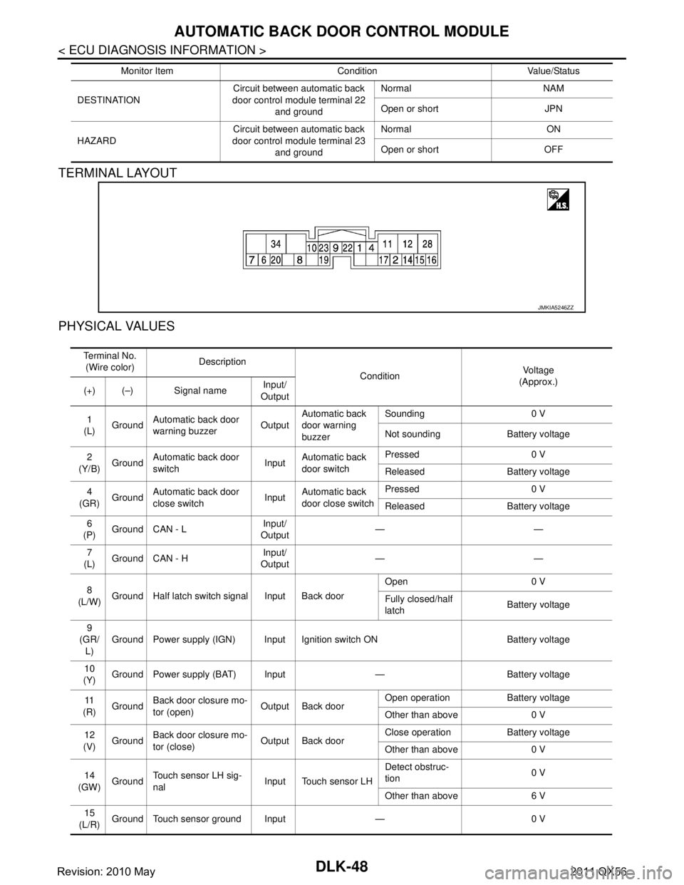
TERMINAL LAYOUT
PHYSICAL VALUES
DESTINATIONCircuit between automatic back
door control module terminal 22
and ground Normal NAM
Open or short JPN
HAZARD Circuit between automatic back
door control module terminal 23 and ground Normal ON
Open or short OFF
Monitor Item Condition Value/Status
JMKIA5246ZZ
Te r m i n a l N o .
(Wire color) Description
Condition Vo l ta g e
(Approx.)
(+) (–) Signal name Input/
Output
1
(L) Ground
Automatic back door
warning buzzer OutputAutomatic back
door warning
buzzer Sounding 0 V
Not sounding Battery voltage
2
(Y/B) Ground Automatic back door
switch InputAutomatic back
door switch Pressed 0 V
Released Battery voltage
4
(GR) Ground Automatic back door
close switch InputAutomatic back
door close switch Pressed 0 V
Released Battery voltage
6
(P) Ground CAN - L
Input/
Output ——
7
(L) Ground CAN - H Input/
Output ——
8
(L/W) Ground Half latch switch signal Input Back door Open 0 V
Fully closed/half
latch
Battery voltage
9
(GR/ L) Ground Power supply (IGN) Input Ignition switch ON Battery voltage
10
(Y) Ground Power supply (BAT) Input — Battery voltage
11
(R) Ground
Back door closure mo-
tor (open) Output Back door Open operation Battery voltage
Other than above 0 V
12
(V) Ground
Back door closure mo-
tor (close) Output Back door Close operation Battery voltage
Other than above 0 V
14
(GW) Ground Touch sensor LH sig-
nal
Input Touch sensor LH Detect obstruc-
tion
0 V
Other than above 6 V
15
(L/R) Ground Touch sensor ground Input — 0 V
Revision: 2010 May2011 QX56
Page 1616 of 5598

DLK-80
< BASIC INSPECTION >
INSPECTION AND ADJUSTMENT
INSPECTION AND ADJUSTMENT
ADDITIONAL SERVICE WHEN REMOVING BATTERY NEGATIVE TERMINAL
ADDITIONAL SERVICE WHEN REMOVING BATTERY NEGATIVE TERMINAL : De-
scription
INFOID:0000000006225867
When the battery is disconnected from the negative terminal, it is necessary to perform initial setting to oper-
ate automatic back door control system normally.
NOTE:
The following specified operations are not performed under the non-initialized condition.
Automatic back door open/close function
Anti-pinch function
ADDITIONAL SERVICE WHEN REMOVING BATTERY NEGATIVE TERMINAL : Work
Procedure
INFOID:0000000006225868
1.INITIALIZATION
1. Fully close the back door manually. (when back door is already fully closed, this operation is not neces-
sary)
2. Perform automatic back door open/close operation of back door.
3. Check for noise or malfunctioning during operation.
4. Check that hazard lamp blinks and that warning buzzer operates.
NOTE:
Never touch back door, or allow foreign materials to be pinched in door, when performing automatic back door
open/close operation of back door, until it is in the fully closed or fully open position.
>> WORK END
ADDITIONAL SERVICE WHEN RE PLACING CONTROL UNIT (BCM)
ADDITIONAL SERVICE WHEN REPLACIN G CONTROL UNIT (BCM) : Description
INFOID:0000000006225869
Perform the system initialization when replacing BCM, replacing Intelligent Key or registering an additional
Intelligent Key.
ADDITIONAL SERVICE WHEN REPLACIN G CONTROL UNIT (BCM) : Work Proce-
dure
INFOID:0000000006225870
Refer to the CONSULT-III operation manual for the initialization procedure.
ADDITIONAL SERVICE WHEN REPLAC ING (AUTOMATIC BACK DOOR CON-
TROL MODULE)
ADDITIONAL SERVICE WHEN REPLACIN G (AUTOMATIC BACK DOOR CONTROL
MODULE) : Description
INFOID:0000000006225871
When replacing control module, or removing connector termi nal, it is necessary to perform initial setting to
operate automatic back door system normally.
NOTE:
The following specified operations are not performed under the non-initialized condition.
Automatic back door open/close function
Anti-pinch function
ADDITIONAL SERVICE WHEN REPLACIN G (AUTOMATIC BACK DOOR CONTROL
MODULE) : Work Procedure
INFOID:0000000006225872
1.INITIALIZATION
Revision: 2010 May2011 QX56
Page 1617 of 5598
INSPECTION AND ADJUSTMENTDLK-81
< BASIC INSPECTION >
C
DE
F
G H
I
J
L
M A
B
DLK
N
O P
1. Fully close the back door manually. (when back door is already fully closed, this operation is not neces-
sary)
2. Perform automatic back door open/close operation of back door.
3. Check for noise or malfunctioning during operation.
4. Check that hazard lamp blinks and that warning buzzer operates.
NOTE:
Never touch back door, or allow foreign materials to be pinched in door, when performing automatic back door
open/close operation of back door, until it is in the fully closed or fully open position.
>> WORK END
Revision: 2010 May2011 QX56
Page 1679 of 5598

INTELLIGENT KEY WARNING BUZZERDLK-143
< DTC/CIRCUIT DIAGNOSIS >
C
DE
F
G H
I
J
L
M A
B
DLK
N
O P
INTELLIGENT KEY WARNING BUZZER
Component Function CheckINFOID:0000000006225958
1.CHECK FUNCTION
1. Select “INTELLIGENT KEY” of “BCM” using CONSULT-III.
2. Select “OUTSIDE BUZZER ” in “ACTIVE TEST” mode.
3. Touch “On” or “Off” to check that it works normally.
Is the inspection result normal?
YES >> Intelligent Key warning buzzer is OK.
NO >> Refer to DLK-143, "
Diagnosis Procedure".
Diagnosis ProcedureINFOID:0000000006225959
1.CHECK FUSE
1. Turn ignition switch OFF.
2. Check 10 A fuse, [No. 6, located in fuse block (J/B)].
Is the inspection result normal?
YES >> GO TO 2.
NO >> Replace the blown fuse after repairing the affected circuit if a fuse is blown.
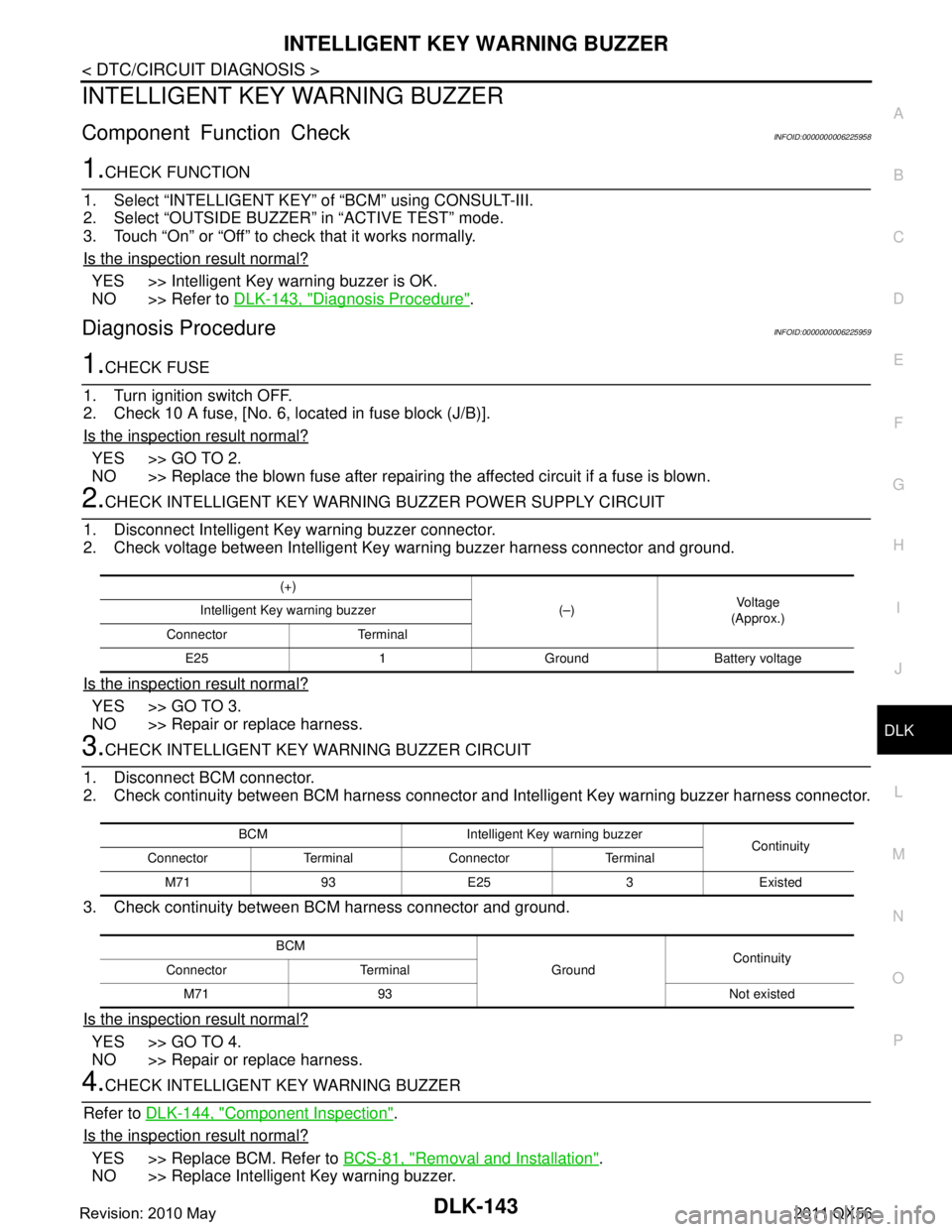
2.CHECK INTELLIGENT KEY WARNING BUZZER POWER SUPPLY CIRCUIT
1. Disconnect Intelligent Key warning buzzer connector.
2. Check voltage between Intelligent Key warning buzzer harness connector and ground.
Is the inspection result normal?
YES >> GO TO 3.
NO >> Repair or replace harness.
3.CHECK INTELLIGENT KEY WARNING BUZZER CIRCUIT
1. Disconnect BCM connector.
2. Check continuity between BCM harness connector and Intelligent Key warning buzzer harness connector.
3. Check continuity between BCM harness connector and ground.
Is the inspection result normal?
YES >> GO TO 4.
NO >> Repair or replace harness.
4.CHECK INTELLIGENT KEY WARNING BUZZER
Refer to DLK-144, "
Component Inspection".
Is the inspection result normal?
YES >> Replace BCM. Refer to BCS-81, "Removal and Installation".
NO >> Replace Intelligent Key warning buzzer.
(+)
(–)Vo l ta g e
(Approx.)
Intelligent Key warning buzzer
Connector Terminal E25 1 Ground Battery voltage
BCM Intelligent Key warning buzzer Continuity
Connector Terminal Connector Terminal
M71 93 E25 3 Existed
BCM GroundContinuity
Connector Terminal
M71 93 Not existed
Revision: 2010 May2011 QX56
Page 1680 of 5598
DLK-144
< DTC/CIRCUIT DIAGNOSIS >
INTELLIGENT KEY WARNING BUZZER
Component Inspection
INFOID:0000000006225960
1.CHECK INTELLIGENT KEY WARNING BUZZER
1. Turn ignition switch OFF.
2. Disconnect Intelligent Key warning buzzer connector.
3. Connect battery power supply directly to Intelli gent Key warning buzzer terminals and check the opera-
tion.
Is the inspection result normal?
YES >> INSPECTION END
NO >> Replace Intelligent Key warning buzzer.
Intelligent Key warning buzzer Operation
Te r m i n a l
(+) ( −)
1 3 Buzzer sounds
Revision: 2010 May2011 QX56
Page 1683 of 5598
INFORMATION DISPLAYDLK-147
< DTC/CIRCUIT DIAGNOSIS >
C
DE
F
G H
I
J
L
M A
B
DLK
N
O P
INFORMATION DISPLAY
Component Function CheckINFOID:0000000006225965
1.CHECK FUNCTION
1. Select “INTELLIGENT KEY” of “BCM” using CONSULT-III.
2. Select “LCD” in “ACTIVE TEST” mode.
3. Check each warning display on meter display.
Is the inspection result normal?
YES >> Information display is OK.
NO >> Refer to DLK-147, "
Diagnosis Procedure".
Diagnosis ProcedureINFOID:0000000006225966
1.CHECK COMBINATION METER
Refer to MWI-29, "
On Board Diagnosis Function".
Is the inspection result normal?
YES >> GO TO 2.
NO >> Repair or replace the malfunctioning parts.
2.CHECK INTERMITTENT INCIDENT
Refer to GI-40, "
Intermittent Incident".
>> INSPECTION END
Revision: 2010 May2011 QX56
Page 1684 of 5598
DLK-148
< DTC/CIRCUIT DIAGNOSIS >
KEY WARNING LAMP
KEY WARNING LAMP
Component Function CheckINFOID:0000000006225967
1.CHECK FUNCTION
1. Select “INTELLIGE NT KEY” of “BCM” using CONSULT-III.
2. Select “INDICATOR” in “ACTIVE TEST” mode.
3. Touch “KEY IND” or “KEY ON” to check that it works normally.
Is the inspection result normal?
YES >> Key warning lamp is OK.
NO >> Refer to DLK-148, "
Diagnosis Procedure".
Diagnosis ProcedureINFOID:0000000006225968
1.CHECK KEY WARNING LAMP
Refer to MWI-29, "
On Board Diagnosis Function".
Is the inspection result normal?
YES >> GO TO 2.
NO >> Repair or replace the malfunctioning parts.
2.CHECK INTERMITTENT INCIDENT
Refer to GI-40, "
Intermittent Incident".
>> INSPECTION END
Revision: 2010 May2011 QX56