2011 INFINITI QX56 warning
[x] Cancel search: warningPage 1492 of 5598
![INFINITI QX56 2011 Factory Service Manual
DAS
WARNING SYSTEMS SWITCHDAS-527
< REMOVAL AND INSTALLATION > [BSW]
C
D
E
F
G H
I
J
K L
M B
N P A
WARNING SYSTEMS SWITCH
Removal and InstallationINFOID:0000000006223984
REMOVAL
1. Remove the instrum INFINITI QX56 2011 Factory Service Manual
DAS
WARNING SYSTEMS SWITCHDAS-527
< REMOVAL AND INSTALLATION > [BSW]
C
D
E
F
G H
I
J
K L
M B
N P A
WARNING SYSTEMS SWITCH
Removal and InstallationINFOID:0000000006223984
REMOVAL
1. Remove the instrum](/manual-img/42/57033/w960_57033-1491.png)
DAS
WARNING SYSTEMS SWITCHDAS-527
< REMOVAL AND INSTALLATION > [BSW]
C
D
E
F
G H
I
J
K L
M B
N P A
WARNING SYSTEMS SWITCH
Removal and InstallationINFOID:0000000006223984
REMOVAL
1. Remove the instrument lower panel (LH). Refer to IP-14, "Removal and Installation".
2. Remove warning systems switch from instrument driver lower panel.
NOTE:
Warning systems switch and automatic back door switch are integrated.
INSTALLATION
Install in the reverse order of removal.
Revision: 2010 May2011 QX56
Page 1495 of 5598
PRECAUTIONSDEF-3
< PRECAUTION >
C
DE
F
G H
I
J
K
M A
B
DEF
N
O P
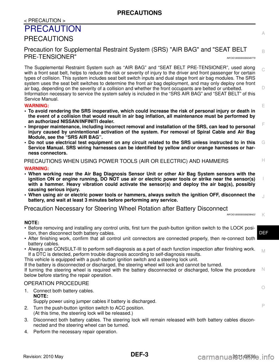
PRECAUTION
PRECAUTIONS
Precaution for Supplemental Restraint System (SRS) "AIR BAG" and "SEAT BELT
PRE-TENSIONER"
INFOID:0000000006349779
The Supplemental Restraint System such as “A IR BAG” and “SEAT BELT PRE-TENSIONER”, used along
with a front seat belt, helps to reduce the risk or severi ty of injury to the driver and front passenger for certain
types of collision. This system includes seat belt switch inputs and dual stage front air bag modules. The SRS
system uses the seat belt switches to determine the front air bag deployment, and may only deploy one front
air bag, depending on the severity of a collision and whether the front occupants are belted or unbelted.
Information necessary to service the system safely is included in the “SRS AIR BAG” and “SEAT BELT” of this
Service Manual.
WARNING:
• To avoid rendering the SRS inoper ative, which could increase the risk of personal injury or death in
the event of a collision that would result in air ba g inflation, all maintenance must be performed by
an authorized NISSAN/INFINITI dealer.
Improper maintenance, including in correct removal and installation of the SRS, can lead to personal
injury caused by unintentional act ivation of the system. For removal of Spiral Cable and Air Bag
Module, see the “SRS AIR BAG”.
Do not use electrical test equipm ent on any circuit related to the SRS unless instructed to in this
Service Manual. SRS wiring harnesses can be identi fied by yellow and/or orange harnesses or har-
ness connectors.
PRECAUTIONS WHEN USING POWER TOOLS (AIR OR ELECTRIC) AND HAMMERS
WARNING:
When working near the Air Bag Diagnosis Sensor Unit or other Air Bag System sensors with the
ignition ON or engine running, DO NOT use air or electric power tools or strike near the sensor(s)
with a hammer. Heavy vibration could activate the sensor(s) and deploy the air bag(s), possibly
causing serious injury.
When using air or electric power tools or hammers , always switch the ignition OFF, disconnect the
battery, and wait at least 3 minutes before performing any service.
Precaution Necessary for Steering Wh eel Rotation after Battery Disconnect
INFOID:0000000006299422
NOTE:
Before removing and installing any control units, first tu rn the push-button ignition switch to the LOCK posi-
tion, then disconnect both battery cables.
After finishing work, confirm that all control unit connectors are connected properly, then re-connect both
battery cables.
Always use CONSULT-III to perform self-diagnosis as a part of each function inspection after finishing work.
If a DTC is detected, perform trouble diagnos is according to self-diagnosis results.
This vehicle is equipped with a push-button ignition switch and a steering lock unit.
If the battery is disconnect ed or discharged, the steering wheel will lock and cannot be turned.
If turning the steering wheel is required with the battery disconnected or discharged, follow the procedure
below before starting the repair operation.
OPERATION PROCEDURE
1. Connect both battery cables. NOTE:
Supply power using jumper cables if battery is discharged.
2. Turn the push-button ignition switch to ACC position. (At this time, the steering lock will be released.)
3. Disconnect both battery cables. The steering lock wil l remain released with both battery cables discon-
nected and the steering wheel can be turned.
4. Perform the necessary repair operation.
Revision: 2010 May2011 QX56
Page 1499 of 5598
DIAGNOSIS SYSTEM (BCM)DEF-7
< SYSTEM DESCRIPTION >
C
DE
F
G H
I
J
K
M A
B
DEF
N
O P
DIAGNOSIS SYSTEM (BCM)
COMMON ITEM
COMMON ITEM : CONSULT-III Fu nction (BCM - COMMON ITEM)INFOID:0000000006349773
APPLICATION ITEM
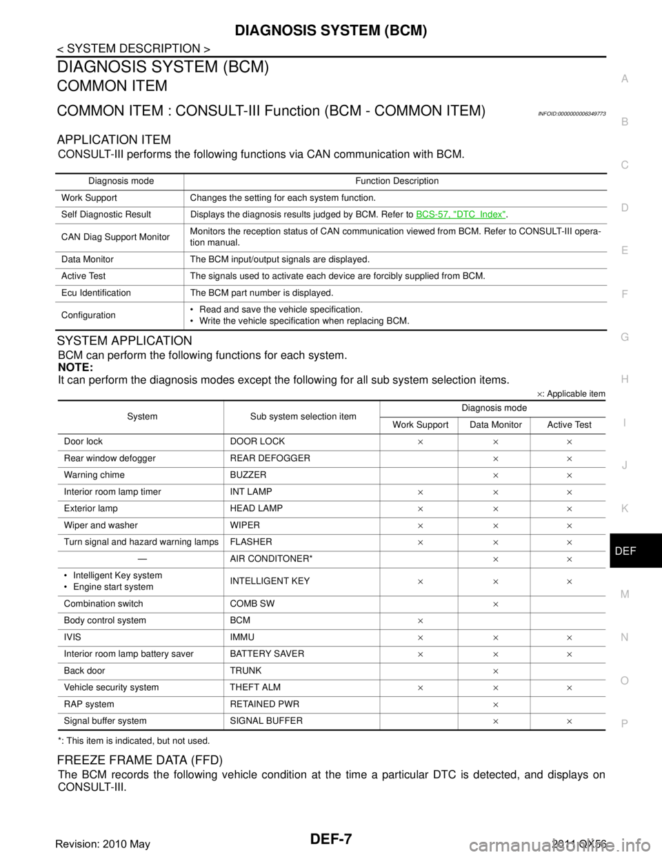
CONSULT-III performs the following functions via CAN communication with BCM.
SYSTEM APPLICATION
BCM can perform the following functions for each system.
NOTE:
It can perform the diagnosis modes except the following for all sub system selection items.
×: Applicable item
*: This item is indicated, but not used.
FREEZE FRAME DATA (FFD)
The BCM records the following vehicle condition at the time a particular DTC is detected, and displays on
CONSULT-III.
Diagnosis mode Function Description
Work Support Changes the setting for each system function.
Self Diagnostic Result Displays the diagnosis results judged by BCM. Refer to BCS-57, "
DTCIndex".
CAN Diag Support Monitor Monitors the reception status of CAN communication viewed from BCM. Refer to CONSULT-III opera-
tion manual.
Data Monitor The BCM input/output signals are displayed.
Active Test The signals used to activate each device are forcibly supplied from BCM.
Ecu Identification The BCM part number is displayed.
Configuration Read and save the vehicle specification.
Write the vehicle specification when replacing BCM.
System Sub system selection item Diagnosis mode
Work Support Data Monitor Active Test
Door lock DOOR LOCK ×××
Rear window defo gger REAR DEFOGGER ××
Warning chime BUZZER ××
Interior room lamp timer INT LAMP ×××
Exterior lamp HEAD LAMP ×××
Wiper and washer WIPER ×××
Turn signal and hazard warning lamps FLASHER ×××
— AIR CONDITONER* ××
Intelligent Key system
Engine start system INTELLIGENT KEY
×××
Combination switch COMB SW ×
Body control system BCM ×
IVIS IMMU ×××
Interior room lamp battery saver BATTERY SAVER ×××
Back door TRUNK ×
Vehicle security system THEFT ALM ×××
RAP system RETAINED PWR ×
Signal buffer system SIGNAL BUFFER ××
Revision: 2010 May2011 QX56
Page 1502 of 5598
DEF-10
< SYSTEM DESCRIPTION >
DIAGNOSIS SYSTEM (IPDM E/R)
DIAGNOSIS SYSTEM (IPDM E/R)
Diagnosis DescriptionINFOID:0000000006349776
AUTO ACTIVE TEST
Description
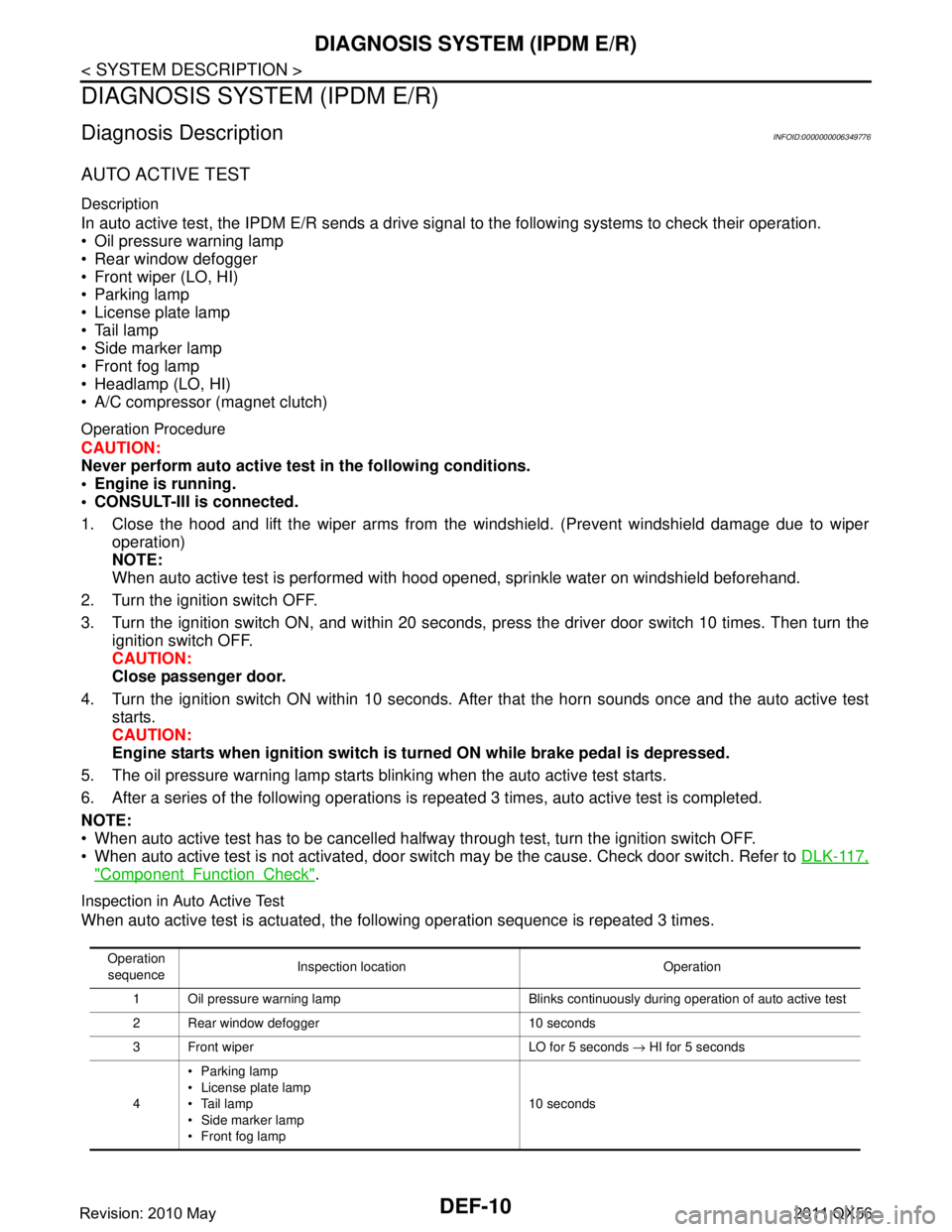
In auto active test, the IPDM E/R sends a drive signal to the following systems to check their operation.
Oil pressure warning lamp
Rear window defogger
Front wiper (LO, HI)
Parking lamp
License plate lamp
Tail lamp
Side marker lamp
Front fog lamp
Headlamp (LO, HI)
A/C compressor (magnet clutch)
Operation Procedure
CAUTION:
Never perform auto active test in the following conditions.
Engine is running.
CONSULT-III is connected.
1. Close the hood and lift the wiper arms from the windshield. (Prevent windshield damage due to wiper
operation)
NOTE:
When auto active test is performed with hood opened, sprinkle water on windshield beforehand.
2. Turn the ignition switch OFF.
3. Turn the ignition switch ON, and within 20 seconds, pr ess the driver door switch 10 times. Then turn the
ignition switch OFF.
CAUTION:
Close passenger door.
4. Turn the ignition switch ON within 10 seconds. Af ter that the horn sounds once and the auto active test
starts.
CAUTION:
Engine starts when igniti on switch is turned ON while brake pedal is depressed.
5. The oil pressure warning lamp starts blinking when the auto active test starts.
6. After a series of the following operations is repeated 3 times, auto active test is completed.
NOTE:
When auto active test has to be cancelled halfway through test, turn the ignition switch OFF.
When auto active test is not activated, door swit ch may be the cause. Check door switch. Refer to DLK-117,
"ComponentFunctionCheck".
Inspection in Auto Active Test
When auto active test is actuated, the following operation sequence is repeated 3 times.
Operation
sequence Inspection location Operation
1 Oil pressure warning lamp Blinks continuously during operation of auto active test
2 Rear window defogger 10 seconds
3 Front wiper LO for 5 seconds → HI for 5 seconds
4 Parking lamp
License plate lamp
Tail lamp
Side marker lamp
Front fog lamp 10 seconds
Revision: 2010 May2011 QX56
Page 1504 of 5598
DEF-12
< SYSTEM DESCRIPTION >
DIAGNOSIS SYSTEM (IPDM E/R)
CONSULT-III Function (IPDM E/R)
INFOID:0000000006349777
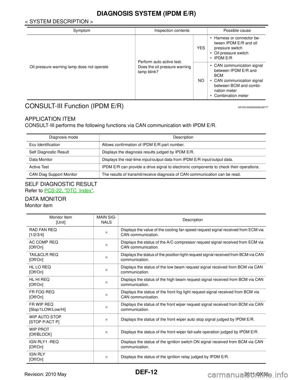
APPLICATION ITEM
CONSULT-III performs the following functions via CAN communication with IPDM E/R.
SELF DIAGNOSTIC RESULT
Refer to PCS-22, "DTCIndex".
DATA MONITOR
Monitor item
Oil pressure warning lamp does not operate Perform auto active test.
Does the oil pressure warning
lamp blink?YES
Harness or connector be-
tween IPDM E/R and oil
pressure switch
Oil pressure switch
IPDM E/R
NO CAN communication signal
between IPDM E/R and
BCM
CAN communication signal
between BCM and combi-
nation meter
Combination meter
Symptom Inspection contents Possible cause
Diagnosis mode Description
Ecu Identification Allows confirmation of IPDM E/R part number.
Self Diagnostic Result Displays the diagnosis results judged by IPDM E/R.
Data Monitor Displays the real-time input/output data from IPDM E/R input/output data.
Active Test IPDM E/R can provide a drive signal to electronic components to check their operations.
CAN Diag Support Monitor The results of transmit/receive diagnosis of CAN communication can be read.
Monitor Item [Unit] MAIN SIG-
NALS Description
RAD FAN REQ
[1/2/3/4] ×Displays the value of the cooling fan speed request signal received from ECM via
CAN communication.
AC COMP REQ
[Off/On] ×Displays the status of the A/C compressor request signal received from ECM via
CAN communication.
TA I L & C L R R E Q
[Off/On] ×
Displays the status of the position light request signal received from BCM via CAN
communication.
HL LO REQ
[Off/On] ×Displays the status of the low beam request signal received from BCM via CAN
communication.
HL HI REQ
[Off/On] ×Displays the status of the high beam request signal received from BCM via CAN
communication.
FR FOG REQ
[Off/On] ×Displays the status of the front fog light request signal received from BCM via
CAN communication.
FR WIP REQ
[Stop/1LOW/Low/Hi] ×
Displays the status of the front wiper request signal received from BCM via CAN
communication.
WIP AUTO STOP
[STOP P/ACT P] ×
Displays the status of the front wiper auto stop signal judged by IPDM E/R.
WIP PROT
[Off/BLOCK] ×
Displays the status of the front wiper fail-safe operation judged by IPDM E/R.
IGN RLY1 -REQ
[Off/On] Displays the status of the ignition switch ON signal received from BCM via CAN
communication.
IGN RLY
[Off/On] ×
Displays the status of the ignition relay judged by IPDM E/R.
Revision: 2010 May2011 QX56
Page 1505 of 5598
![INFINITI QX56 2011 Factory Service Manual
DIAGNOSIS SYSTEM (IPDM E/R)DEF-13
< SYSTEM DESCRIPTION >
C
DE
F
G H
I
J
K
M A
B
DEF
N
O P
ACTIVE TEST
Te s t i t e m
PUSH SW
[Off/On] Displays the status of the push-button ignition switch judged by INFINITI QX56 2011 Factory Service Manual
DIAGNOSIS SYSTEM (IPDM E/R)DEF-13
< SYSTEM DESCRIPTION >
C
DE
F
G H
I
J
K
M A
B
DEF
N
O P
ACTIVE TEST
Te s t i t e m
PUSH SW
[Off/On] Displays the status of the push-button ignition switch judged by](/manual-img/42/57033/w960_57033-1504.png)
DIAGNOSIS SYSTEM (IPDM E/R)DEF-13
< SYSTEM DESCRIPTION >
C
DE
F
G H
I
J
K
M A
B
DEF
N
O P
ACTIVE TEST
Te s t i t e m
PUSH SW
[Off/On] Displays the status of the push-button ignition switch judged by IPDM E/R.
INTER/NP SW
[Off/On] Displays the status of the shift position judged by IPDM E/R.
ST RLY CONT
[Off/On] Displays the status of the starter relay status signal received from BCM via CAN
communication.
IHBT RLY -REQ
[Off/On] Displays the status of the starter control relay signal received from BCM via CAN
communication.
ST/INHI RLY
[Off/ ST ON/INHI ON/UNKWN] Displays the status of the starter relay and starter control relay judged by IPDM
E/R.
DETENT SW
[Off/On] Displays the status of the A/T shift selector (detention switch) judged by IPDM E/
R.
S/L RLY -REQ
[Off/On] Displays the status of the steering lock relay signal received from BCM via CAN
communication.
S/L STATE
[LOCK/UNLK/UNKWN] Displays the status of the steering lock judged by IPDM E/R.
OIL P SW
[Open/Close] Displays the status of the oil pressure switch judged by IPDM E/R.
HOOD SW
[Off/On] Displays the status of the hood switch judged by IPDM E/R.
HL WASHER REQ
[Off/On] Displays the status of the headlamp washer request signal received from BCM via
CAN communication.
THFT HRN REQ
[Off/On] Displays the status of the theft warning horn request signal received from BCM
via CAN communication.
HORN CHIRP
[Off/On] Displays the status of the horn reminder signal received from BCM via CAN com-
munication.
Monitor Item
[Unit] MAIN SIG-
NALS Description
Test item Operation Description
CORNERING LAMP LH
NOTE:
This item is indicated, but cannot be tested.
RH
HORN On Operates horn relay for 20 ms.
REAR DEFOGGER Off OFF
On Operates the rear window defogger relay.
FRONT WIPER Off OFF
Lo Operates the front wiper relay.
Hi Operates the front wiper relay and front wiper high relay.
MOTOR FAN* 1OFF
2 Transmits 50% pulse duty signal (PWM signal) to the cooling fan control module.
3 Transmits 75% pulse duty signal (PWM signal) to the cooling fan control module.
4
Transmits 100% pulse duty signal (PWM signal) to the cooling fan control mod-
ule.
HEAD LAMP WASHER On Operates the headlamp washer relay for 1 second.
Revision: 2010 May2011 QX56
Page 1537 of 5598
DLK-1
BODY EXTERIOR, DOORS, ROOF & VEHICLE SECURITY
C
D
E
F
G H
I
J
L
M
SECTION DLK
A
B
DLK
N
O P
CONTENTS
DOOR & LOCK
PRECAUTION ................ ...............................8
PRECAUTIONS .............................................. .....8
Precaution for Supplemental Restraint System
(SRS) "AIR BAG" and "SEAT BELT PRE-TEN-
SIONER" ............................................................. ......
8
Precaution Necessary for Steering Wheel Rota-
tion after Battery Disconnect .....................................
8
Precautions For Xenon Headlamp Service ...............9
Work ..........................................................................9
PREPARATION ...........................................10
PREPARATION .............................................. ....10
Commercial Service Tools .................................. ....10
SYSTEM DESCRIPTION .............................11
COMPONENT PARTS ................................... ....11
DOOR LOCK SYSTEM .............................................11
DOOR LOCK SYSTEM :
Component Parts Location ................................ ....
11
DOOR LOCK SYSTEM : Component Description ....12
AUTOMATIC BACK DOOR SYSTEM .......................13
AUTOMATIC BACK DOOR SYSTEM :
Component Parts Location ................................ ....
14
AUTOMATIC BACK DOOR SYSTEM :
Component Description ..........................................
15
SYSTEM (POWER DOOR LOCK SYSTEM) .....16
System Diagram .................................................. ....16
System Description .................................................16
SYSTEM (INTELLIGENT KEY SYSTEM) ..........18
INTELLIGENT KEY SYSTEM ...................................18
INTELLIGENT KEY SYSTEM : System Diagram ....18
INTELLIGENT KEY SYSTEM : System Descrip-
tion ..........................................................................
18
DOOR LOCK FUNCTION ...................................... ....19
DOOR LOCK FUNCTION : System Diagram ..........19
DOOR LOCK FUNCTION : System Description .....19
BACK DOOR OPEN FUNCTION ........................... ....21
BACK DOOR OPEN FUNCTION : System Dia-
gram ........................................................................
21
BACK DOOR OPEN FUNCTION : System De-
scription ...................................................................
21
REMOTE KEYLESS ENTRY FUNCTION ..................23
REMOTE KEYLESS ENTRY FUNCTION : Sys-
tem Diagram ........................................................ ....
23
REMOTE KEYLESS ENTRY FUNCTION : Sys-
tem Description ........................................................
23
KEY REMINDER FUNCTION ................................ ....25
KEY REMINDER FUNCTION : System Diagram ....25
KEY REMINDER FUNCTION : System Descrip-
tion ...........................................................................
26
WELCOME LIGHT FUNCTION ............................. ....26
WELCOME LIGHT FUNCTION : System Diagram
....
26
WELCOME LIGHT FUNCTION : System Descrip-
tion ...........................................................................
26
WARNING FUNCTION .......................................... ....27
WARNING FUNCTION : System Description ..........27
SYSTEM (AUTOMATIC BACK DOOR SYS-
TEM) ..................................................................
31
System Diagram .................................................. ....31
System Description ..................................................31
SYSTEM (INTEGRATED HOMELINK
TRANSMITTER) ................................................
37
System Description .............................................. ....37
DIAGNOSIS SYSTEM (BCM) ...........................38
COMMON ITEM ..................................................... ....38
COMMON ITEM : CONSULT-III Function (BCM -
COMMON ITEM) .....................................................
38
Revision: 2010 May2011 QX56
Page 1539 of 5598
DLK-3
C
DE
F
G H
I
J
L
M A
B
DLK
N
O P
Diagnosis Procedure ...........................................
....
98
B2423 AUTOMATIC BACK DOOR MOTOR
OPERATION TIME .............................................
99
DTC Logic ........................................................... ....99
Diagnosis Procedure ...............................................99
B2424 CLOSURE CONDITION ........................100
DTC Logic ........................................................... ..100
Diagnosis Procedure .............................................100
Component Inspection ..........................................101
B2425 AUTOMATIC BACK DOOR CONTROL
UNIT ..................................................................
103
DTC Logic ........................................................... ..103
Diagnosis Procedure .............................................103
B2621 INSIDE ANTENNA ................................104
DTC Logic ........................................................... ..104
Diagnosis Procedure .............................................104
B2622 INSIDE ANTENNA ................................106
DTC Logic ........................................................... ..106
Diagnosis Procedure .............................................106
B2623 INSIDE ANTENNA ................................108
DTC Logic ........................................................... ..108
Diagnosis Procedure .............................................108
B2626 OUTSIDE ANTENNA ............................110
DTC Logic ........................................................... ..110
Diagnosis Procedure .............................................110
B2627 OUTSIDE ANTENNA ............................112
DTC Logic ........................................................... ..112
Diagnosis Procedure .............................................112
B2628 OUTSIDE ANTENNA ............................114
DTC Logic ........................................................... ..114
Diagnosis Procedure .............................................114
POWER SUPPLY AND GROUND CIRCUIT ....116
AUTOMATIC BACK DOOR CONTROL UNIT ...... ..116
AUTOMATIC BACK DOOR CONTROL UNIT : Di-
agnosis Procedure ................................................
116
DOOR SWITCH ................................................117
Component Function Check .............................. ..117
Diagnosis Procedure .............................................117
Component Inspection ..........................................119
BACK DOOR SWITCH .....................................120
Component Function Check .............................. ..120
Diagnosis Procedure .............................................120
Component Inspection ..........................................121
DOOR LOCK AND UNLOCK SWITCH ............122
DRIVER SIDE ........................................................ ..122
DRIVER SIDE : Component Function Check ......122
DRIVER SIDE : Diagnosis Procedure ...................122
PASSENGER SIDE ..................................................122
PASSENGER SIDE :
Component Function Check .............................. ..
122
PASSENGER SIDE : Diagnosis Procedure ..........122
DOOR LOCK ACTUATOR ..............................123
DRIVER SIDE ......................................................... ..123
DRIVER SIDE : Component Function Check ......123
DRIVER SIDE : Diagnosis Procedure ...................123
PASSENGER SIDE ..................................................124
PASSENGER SIDE :
Component Function Check .............................. ..
124
PASSENGER SIDE : Diagnosis Procedure ..........124
REAR LH ................................................................ ..125
REAR LH : Component Function Check ..............125
REAR LH : Diagnosis Procedure ...........................125
REAR RH ............................................................... ..126
REAR RH : Component Function Check .............126
REAR RH : Diagnosis Procedure ..........................126
FUEL LID LOCK ACTUATOR ........................128
Component Function Check ................................128
Diagnosis Procedure .............................................128
UNLOCK SENSOR .........................................130
Component Function Check ................................130
Diagnosis Procedure .............................................130
Component Inspection ...........................................131
DOOR KEY CYLINDER SWITCH ...................132
Component Function Check ..................................132
Diagnosis Procedure .............................................132
Component Inspection ...........................................133
REMOTE KEYLESS ENTRY RECEIVER .......134
Component Function Check ................................134
Diagnosis Procedure .............................................134
DOOR REQUEST SWITCH ............................137
Component Function Check ................................137
Diagnosis Procedure .............................................137
Component Inspection ...........................................138
BACK DOOR REQUEST SWITCH .................139
Component Function Check ................................139
Diagnosis Procedure .............................................139
Component Inspection ...........................................140
BACK DOOR OPENER SWITCH ...................141
Component Function Check ................................141
Diagnosis Procedure .............................................141
Component Inspection ...........................................142
INTELLIGENT KEY WARNING BUZZER .......143
Component Function Check ................................143
Diagnosis Procedure .............................................143
Component Inspection ...........................................144
INTELLIGENT KEY .........................................145
Revision: 2010 May2011 QX56