2011 INFINITI QX56 boot
[x] Cancel search: bootPage 3678 of 5598
MA-8
< PERIODIC MAINTENANCE >
PERIODIC MAINTENANCE
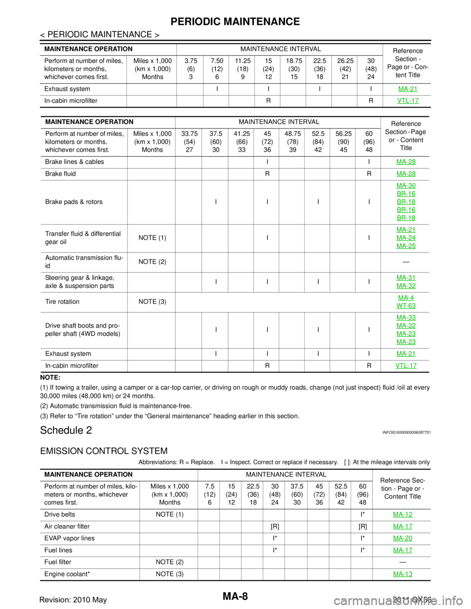
NOTE:
(1) If towing a trailer, using a camper or a car-top carrier, or driving on rough or muddy roads, change (not just inspect) fluid /oil at every
30,000 miles (48,000 km) or 24 months.
(2) Automatic transmission fluid is maintenance-free.
(3) Refer to “Tire rotation” unde r the “General maintenance” heading earlier in this section.
Schedule 2INFOID:0000000006287731
EMISSION CONTROL SYSTEM
Abbreviations: R = Replace. I = Inspec t. Correct or replace if necessary. [ ]: At the mileage intervals only
Exhaust system I I I I MA-21
In-cabin microfilter R RVTL-17
MAINTENANCE OPERATIONMAINTENANCE INTERVAL
Reference
Section -
Page or - Con- tent Title
Perform at number of miles,
kilometers or months,
whichever comes first. Miles x 1,000
(km x 1,000)
Months 3.75
(6)
3 7.50
(12)
6 11 . 2 5
(18)
9 15
(24)
12 18.75
(30)
15 22.5
(36)
18 26.25
(42)
21 30
(48)
24
MAINTENANCE OPERATION MAINTENANCE INTERVAL
Reference
Section - Page
or - Content Title
Perform at number of miles,
kilometers or months,
whichever comes first. Miles x 1,000
(km x 1,000) Months 33.75
(54)27 37.5
(60) 30 41.25
(66)33 45
(72) 36 48.75
(78)39 52.5
(84) 42 56.25
(90)45 60
(96) 48
Brake lines & cables I I MA-28
Brake fluid R RMA-28
Brake pads & rotors I I I IMA-30
BR-16
BR-18
BR-16
BR-18
Transfer fluid & differential
gear oil
NOTE (1) I I MA-21MA-24
MA-25
Automatic transmission flu-
id
NOTE (2)
—
Steering gear & linkage,
axle & suspension parts IIII
MA-31
MA-32
Tire rotation NOTE (3) MA-4WT-63
Drive shaft boots and pro-
peller shaft (4WD models)IIII MA-33MA-22
MA-23
MA-23
Exhaust system I I I I
MA-21
In-cabin microfilter R RVTL-17
MAINTENANCE OPERATIONMAINTENANCE INTERVAL
Reference Sec-
tion - Page or -
Content Title
Perform at number of miles, kilo-
meters or months, whichever
comes first. Miles x 1,000
(km x 1,000)
Months 7.5
(12)
6 15
(24)
12 22.5
(36)
18 30
(48)
24 37.5
(60)
30 45
(72)
36 52.5
(84)
42 60
(96)
48
Drive belts NOTE (1) I* MA-12
Air cleaner filter [R] [R]MA-17
EVAP vapor lines I* I*MA-20
Fuel lines I* I*MA-17
Fuel filter NOTE (2) —
Engine coolant* NOTE (3) MA-13
Revision: 2010 May2011 QX56
Page 3679 of 5598
PERIODIC MAINTENANCEMA-9
< PERIODIC MAINTENANCE >
C
DE
F
G H
I
J
K L
M B
MA
N
O A
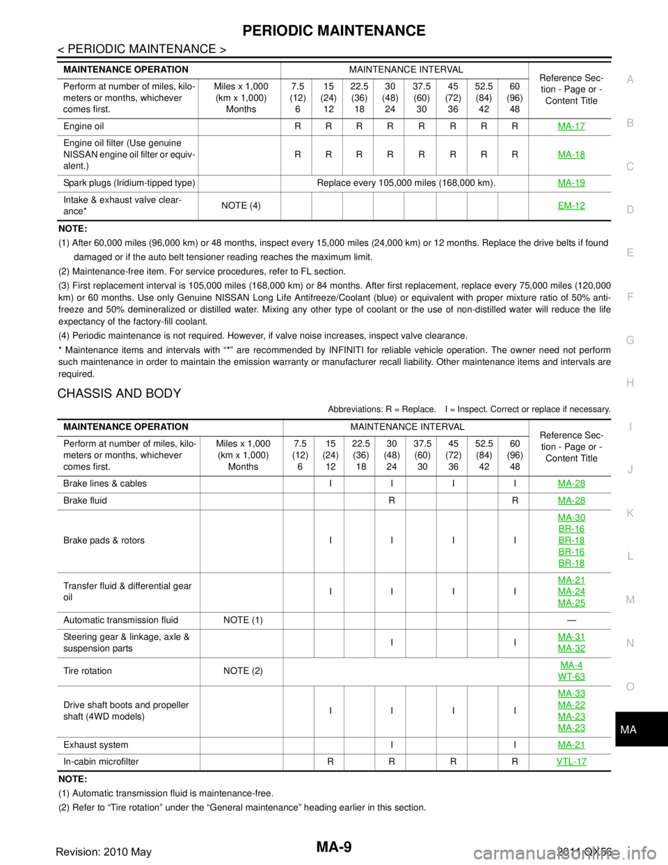
NOTE:
(1) After 60,000 miles (96,000 km) or 48 months, inspect every 15,000 miles (24,000 km) or 12 months. Replace the drive belts i
f found
damaged or if the auto belt tensioner reading reaches the maximum limit.
(2) Maintenance-free item. For service procedures, refer to FL section.
(3) First replacement interval is 105,000 miles (168,000 km) or 84 months. After first replacement, replace every 75,000 miles (120,000
km) or 60 months. Use only Genu ine NISSAN Long Life Antifreeze/Coo lant (blue) or equivalent with proper mixture ratio of 50% anti-
freeze and 50% demineralized or distilled water. Mixing any other type of coolant or the use of non-distilled water will reduce the life
expectancy of the factory-fill coolant.
(4) Periodic maintenance is not required. However, if valve noise increases, inspect valve clearance.
* Maintenance items and intervals with “*” are recommended by INFINITI for reliable vehicle operation. The owner need not perfo rm
such maintenance in order to maintain the emission warranty or manufacturer recall liability. Other maintenance items and inter vals are
required.
CHASSIS AND BODY
Abbreviations: R = Replace. I = Inspec t. Correct or replace if necessary.
NOTE:
(1) Automatic transmission fluid is maintenance-free.
(2) Refer to “Tire rotation” under the “General maintenance” heading earlier in this section.
Engine oil R R R R R R R R
MA-17
Engine oil filter (Use genuine
NISSAN engine oil filter or equiv-
alent.)RRRR R RRR
MA-18
Spark plugs (Iridium-tipped type) Replace every 105,000 miles (168,000 km). MA-19
Intake & exhaust valve clear-
ance*NOTE (4)
EM-12
MAINTENANCE OPERATIONMAINTENANCE INTERVAL
Reference Sec-
tion - Page or -
Content Title
Perform at number of miles, kilo-
meters or months, whichever
comes first. Miles x 1,000
(km x 1,000)
Months 7.5
(12)
6 15
(24)
12 22.5
(36)
18 30
(48)
24 37.5
(60)
30 45
(72)
36 52.5
(84)
42 60
(96)
48
MAINTENANCE OPERATION MAINTENANCE INTERVAL
Reference Sec-
tion - Page or - Content Title
Perform at number of miles, kilo-
meters or months, whichever
comes first. Miles x 1,000
(km x 1,000) Months 7.5
(12) 6 15
(24) 12 22.5
(36) 18 30
(48) 24 37.5
(60) 30 45
(72) 36 52.5
(84) 42 60
(96) 48
Brake lines & cables I I I I MA-28
Brake fluid R RMA-28
Brake pads & rotors I I I IMA-30
BR-16
BR-18
BR-16
BR-18
Transfer fluid & differential gear
oil
IIIIMA-21MA-24
MA-25
Automatic transmission fluid NOTE (1)
—
Steering gear & linkage, axle &
suspension parts II
MA-31
MA-32
Tire rotation NOTE (2) MA-4WT-63
Drive shaft boots and propeller
shaft (4WD models) IIIIMA-33MA-22
MA-23
MA-23
Exhaust system I I
MA-21
In-cabin microfilter R R R RVTL-17
Revision: 2010 May2011 QX56
Page 3702 of 5598
MA-32
< PERIODIC MAINTENANCE >
CHASSIS MAINTENANCE
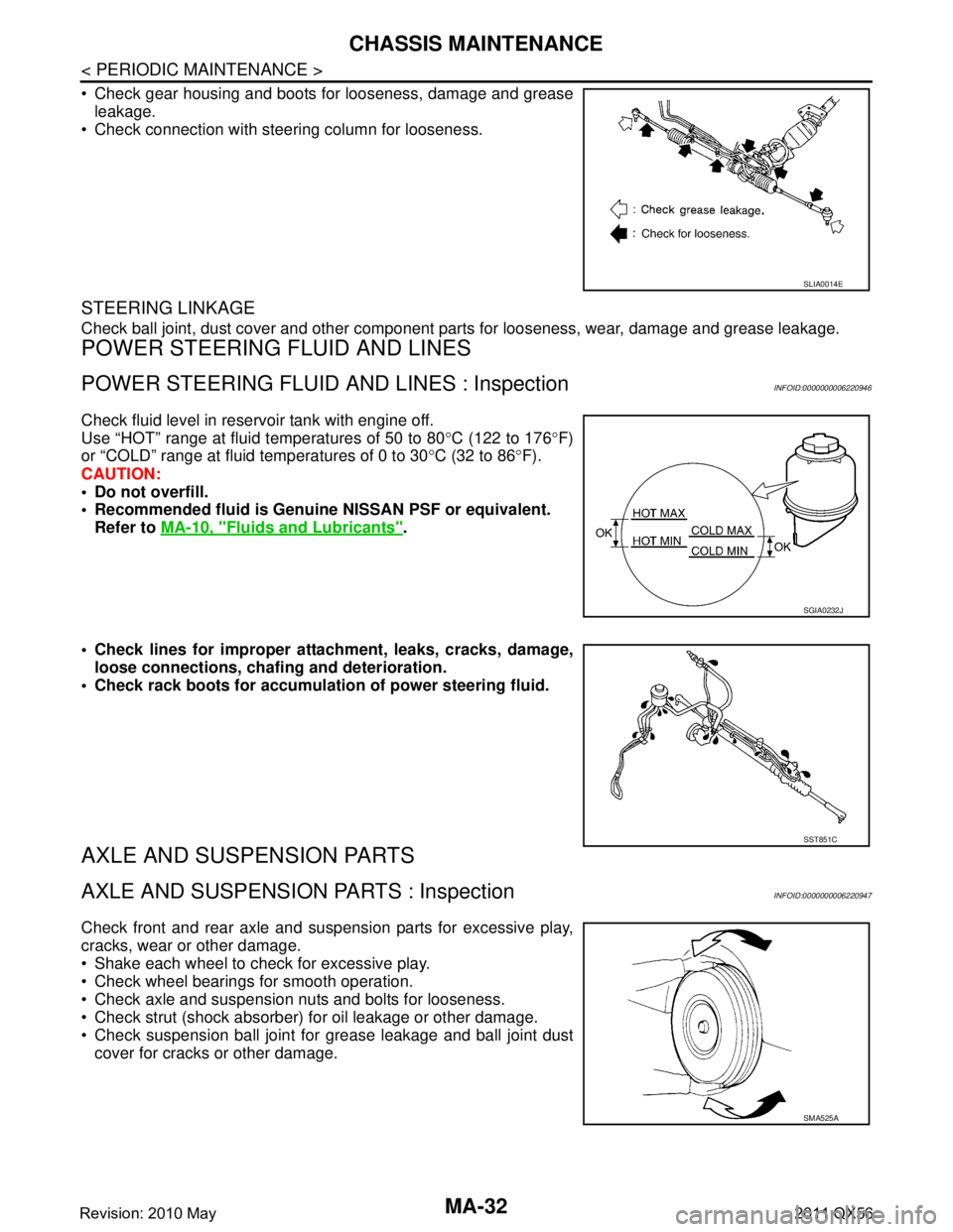
Check gear housing and boots for looseness, damage and greaseleakage.
Check connection with steering column for looseness.
STEERING LINKAGE
Check ball joint, dust cover and other component parts for looseness, wear, damage and grease leakage.
POWER STEERING FLUID AND LINES
POWER STEERING FLUID AND LINES : InspectionINFOID:0000000006220946
Check fluid level in reservoir tank with engine off.
Use “HOT” range at fluid temperatures of 50 to 80 °C (122 to 176 °F)
or “COLD” range at fluid temperatures of 0 to 30 °C (32 to 86 °F).
CAUTION:
Do not overfill.
Recommended fluid is Genuine NISSAN PSF or equivalent.
Refer to MA-10, "
Fluids and Lubricants".
Check lines for improper attachment, leaks, cracks, damage, loose connections, chaf ing and deterioration.
Check rack boots for accumulati on of power steering fluid.
AXLE AND SUSPENSION PARTS
AXLE AND SUSPENSION PARTS : InspectionINFOID:0000000006220947
Check front and rear axle and suspension parts for excessive play,
cracks, wear or other damage.
Shake each wheel to check for excessive play.
Check wheel bearings for smooth operation.
Check axle and suspension nuts and bolts for looseness.
Check strut (shock absorber) for oil leakage or other damage.
Check suspension ball joint for grease leakage and ball joint dust
cover for cracks or other damage.
SLIA0014E
SGIA0232J
SST851C
SMA525A
Revision: 2010 May2011 QX56
Page 3703 of 5598
CHASSIS MAINTENANCEMA-33
< PERIODIC MAINTENANCE >
C
DE
F
G H
I
J
K L
M B
MA
N
O A
DRIVE SHAFT
DRIVE SHAFT : InspectionINFOID:0000000006220948
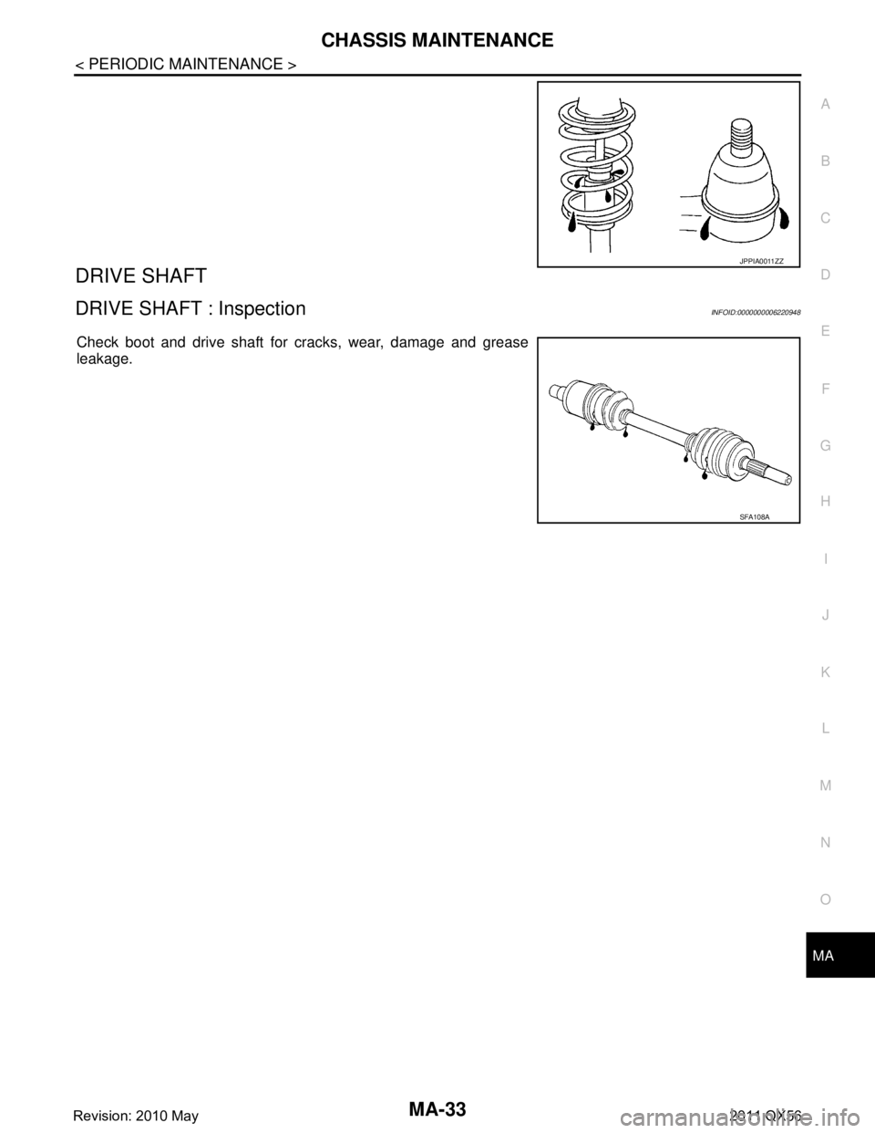
Check boot and drive shaft for cracks, wear, damage and grease
leakage.
JPPIA0011ZZ
SFA108A
Revision: 2010 May2011 QX56
Page 4199 of 5598
PREPARATIONRAX-3
< PREPARATION >
CEF
G H
I
J
K L
M A
B
RAX
N
O P
PREPARATION
PREPARATION
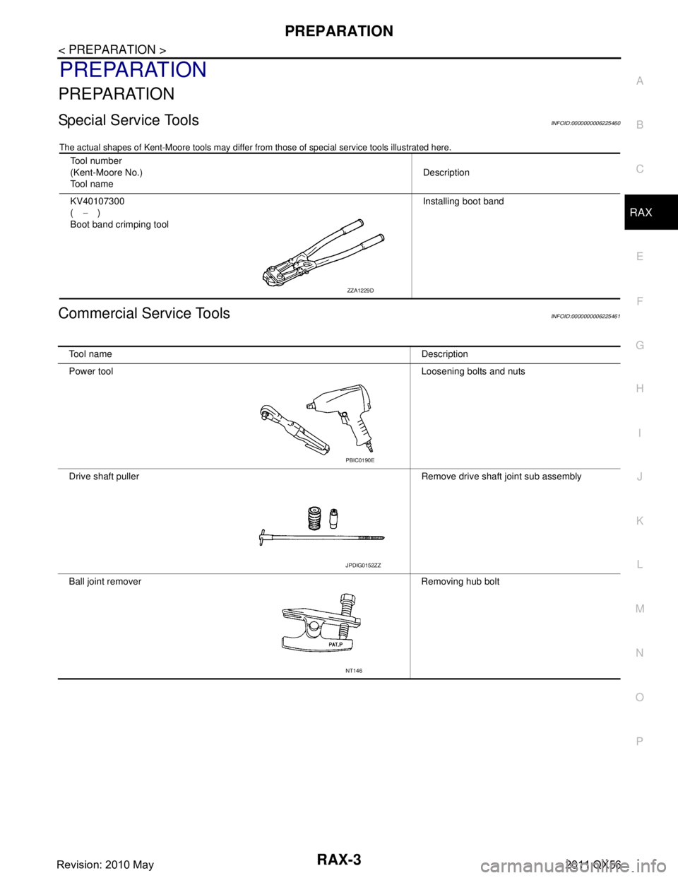
Special Service ToolsINFOID:0000000006225460
The actual shapes of Kent-Moore t ools may differ from those of special service tools illustrated here.
Commercial Service ToolsINFOID:0000000006225461
Tool number
(Kent-Moore No.)
Tool name Description
KV40107300
( − )
Boot band crimping tool Installing boot band
ZZA1229D
Tool name
Description
Power tool Loosening bolts and nuts
Drive shaft puller Remove drive shaft joint sub assembly
Ball joint remover Removing hub bolt
PBIC0190E
JPDIG0152ZZ
NT146
Revision: 2010 May2011 QX56
Page 4202 of 5598
RAX-6
< PERIODIC MAINTENANCE >
REAR DRIVE SHAFT
REAR DRIVE SHAFT
InspectionINFOID:0000000006225464
Check the following items, and replace the part if necessary.
Check drive shaft mounting point and joint for looseness and other damage.CAUTION:
Replace entire drive shaft assembly when noi se or vibration occurs from drive shaft.
Check boot for cracks and other damage.
Revision: 2010 May2011 QX56
Page 4204 of 5598
RAX-8
< REMOVAL AND INSTALLATION >
REAR WHEEL HUB AND HOUSING
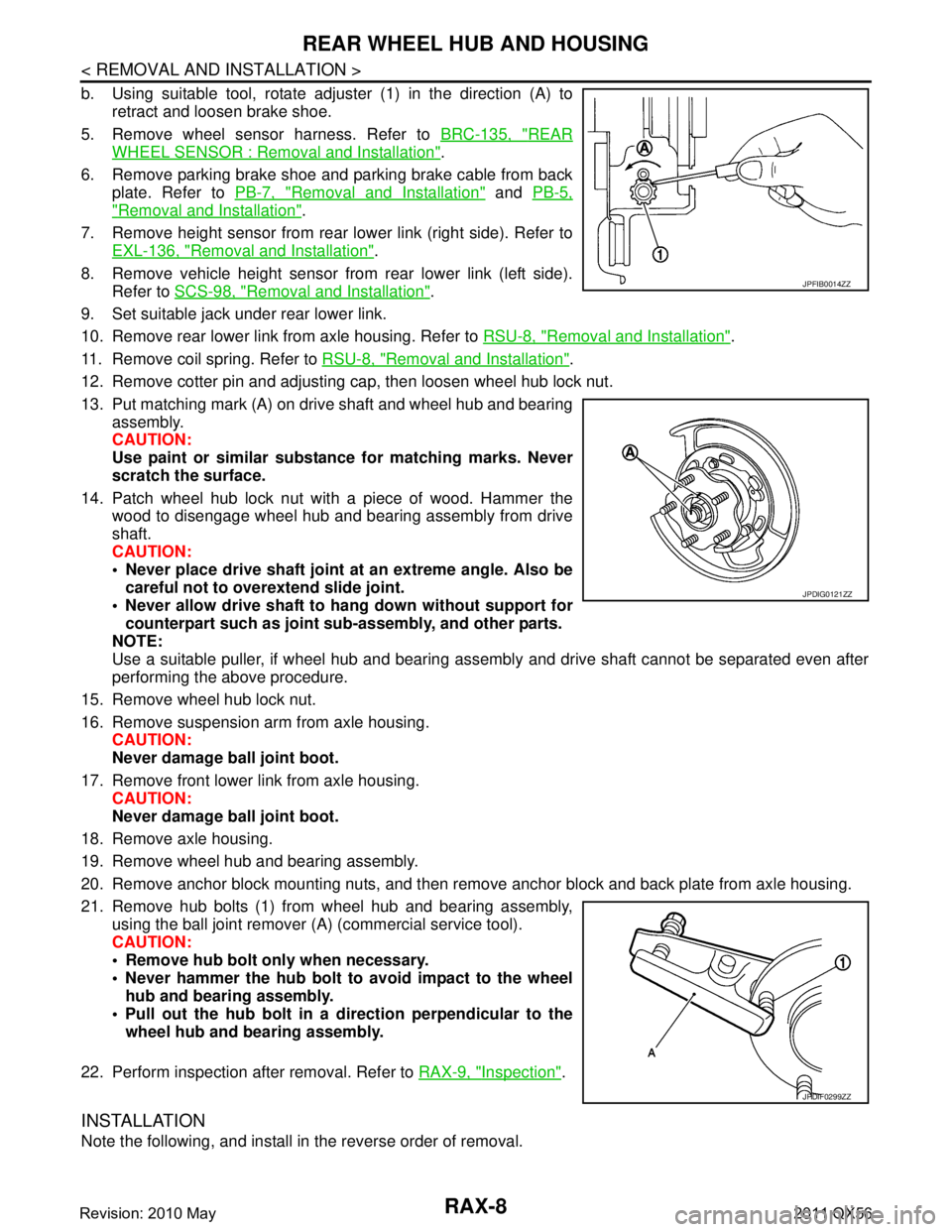
b. Using suitable tool, rotate adjuster (1) in the direction (A) toretract and loosen brake shoe.
5. Remove wheel sensor harness. Refer to BRC-135, "
REAR
WHEEL SENSOR : Removal and Installation".
6. Remove parking brake shoe and parking brake cable from back plate. Refer to PB-7, "
Removal and Installation" and PB-5,
"Removal and Installation".
7. Remove height sensor from rear lower link (right side). Refer to EXL-136, "
Removal and Installation".
8. Remove vehicle height sensor from rear lower link (left side). Refer to SCS-98, "
Removal and Installation".
9. Set suitable jack under rear lower link.
10. Remove rear lower link from axle housing. Refer to RSU-8, "
Removal and Installation".
11. Remove coil spring. Refer to RSU-8, "
Removal and Installation".
12. Remove cotter pin and adjusting cap, then loosen wheel hub lock nut.
13. Put matching mark (A) on drive shaft and wheel hub and bearing assembly.
CAUTION:
Use paint or similar substance for matching marks. Never
scratch the surface.
14. Patch wheel hub lock nut with a piece of wood. Hammer the wood to disengage wheel hub and bearing assembly from drive
shaft.
CAUTION:
Never place drive shaft joint at an extreme angle. Also be
careful not to over extend slide joint.
Never allow drive shaft to ha ng down without support for
counterpart such as joint sub-assembly, and other parts.
NOTE:
Use a suitable puller, if wheel hub and bearing assembly and drive shaft cannot be separated even after
performing the above procedure.
15. Remove wheel hub lock nut.
16. Remove suspension arm from axle housing. CAUTION:
Never damage ball joint boot.
17. Remove front lower link from axle housing. CAUTION:
Never damage ball joint boot.
18. Remove axle housing.
19. Remove wheel hub and bearing assembly.
20. Remove anchor block mounting nuts, and then remove anchor block and back plate from axle housing.
21. Remove hub bolts (1) from wheel hub and bearing assembly, using the ball joint remover (A) (commercial service tool).
CAUTION:
Remove hub bolt only when necessary.
Never hammer the hub bolt to avoid impact to the wheel
hub and bearing assembly.
Pull out the hub bolt in a direction perpendicular to the wheel hub and bearing assembly.
22. Perform inspection after removal. Refer to RAX-9, "
Inspection".
INSTALLATION
Note the following, and install in the reverse order of removal.
JPFIB0014ZZ
JPDIG0121ZZ
JPDIF0299ZZ
Revision: 2010 May2011 QX56
Page 4205 of 5598
REAR WHEEL HUB AND HOUSINGRAX-9
< REMOVAL AND INSTALLATION >
CEF
G H
I
J
K L
M A
B
RAX
N
O P
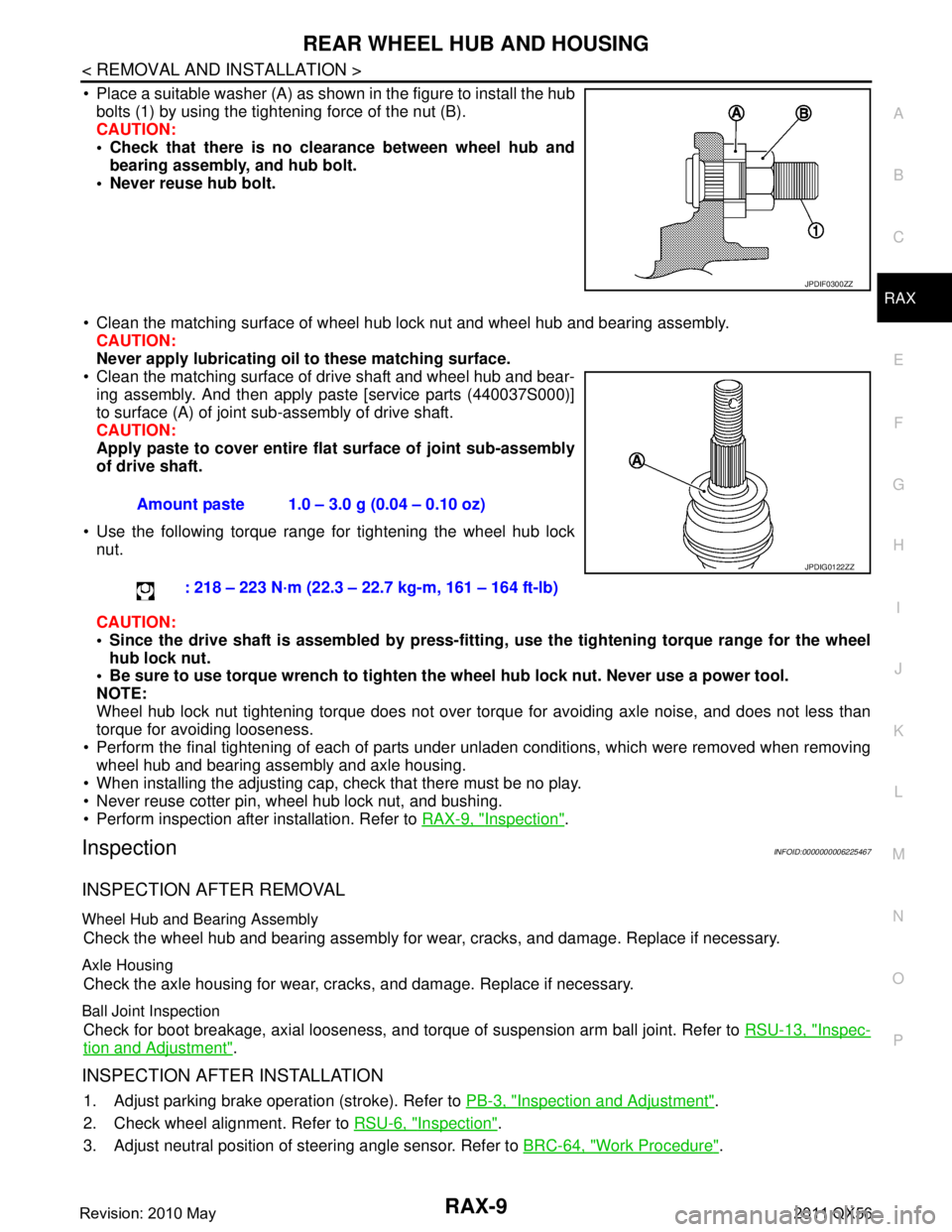
Place a suitable washer (A) as shown in the figure to install the hub bolts (1) by using the tightening force of the nut (B).
CAUTION:
Check that there is no cl earance between wheel hub and
bearing assembly, and hub bolt.
Never reuse hub bolt.
Clean the matching surface of wheel hub lock nut and wheel hub and bearing assembly. CAUTION:
Never apply lubricating oi l to these matching surface.
Clean the matching surface of drive shaft and wheel hub and bear-
ing assembly. And then apply paste [service parts (440037S000)]
to surface (A) of joint sub-assembly of drive shaft.
CAUTION:
Apply paste to cover entire fl at surface of joint sub-assembly
of drive shaft.
Use the following torque range for tightening the wheel hub lock nut.
CAUTION:
Since the drive shaft is assembled by press-fitting , use the tightening torque range for the wheel
hub lock nut.
Be sure to use torque wrench to tighten th e wheel hub lock nut. Never use a power tool.
NOTE:
Wheel hub lock nut tightening torque does not over tor que for avoiding axle noise, and does not less than
torque for avoiding looseness.
Perform the final tightening of each of parts under unladen conditions, which were removed when removing wheel hub and bearing assembly and axle housing.
When installing the adjusting cap, check that there must be no play.
Never reuse cotter pin, wheel hub lock nut, and bushing.
Perform inspection after installation. Refer to RAX-9, "
Inspection".
InspectionINFOID:0000000006225467
INSPECTION AFTER REMOVAL
Wheel Hub and Bearing Assembly
Check the wheel hub and bearing assembly for wear, cracks, and damage. Replace if necessary.
Axle Housing
Check the axle housing for wear, cracks, and damage. Replace if necessary.
Ball Joint Inspection
Check for boot breakage, axial looseness, and torque of suspension arm ball joint. Refer to RSU-13, "Inspec-
tion and Adjustment".
INSPECTION AFTER INSTALLATION
1. Adjust parking brake operation (stroke). Refer to PB-3, "Inspection and Adjustment".
2. Check wheel alignment. Refer to RSU-6, "
Inspection".
3. Adjust neutral position of steering angle sensor. Refer to BRC-64, "
Work Procedure".
JPDIF0300ZZ
Amount paste 1.0 – 3.0 g (0.04 – 0.10 oz)
: 218 – 223 N·m (22.3 – 22.7 kg-m, 161 – 164 ft-lb)
JPDIG0122ZZ
Revision: 2010 May2011 QX56