2011 INFINITI QX56 boot
[x] Cancel search: bootPage 2927 of 5598
![INFINITI QX56 2011 Factory Service Manual
FRONT DRIVE SHAFTFAX-27
< REMOVAL AND INSTALLATION > [4WD]
C
EF
G H
I
J
K L
M A
B
FA X
N
O P
2. Install boot and boot bands to shaft. CAUTION:
Wrap serration on shaft with tape (A) to protect the b INFINITI QX56 2011 Factory Service Manual
FRONT DRIVE SHAFTFAX-27
< REMOVAL AND INSTALLATION > [4WD]
C
EF
G H
I
J
K L
M A
B
FA X
N
O P
2. Install boot and boot bands to shaft. CAUTION:
Wrap serration on shaft with tape (A) to protect the b](/manual-img/42/57033/w960_57033-2926.png)
FRONT DRIVE SHAFTFAX-27
< REMOVAL AND INSTALLATION > [4WD]
C
EF
G H
I
J
K L
M A
B
FA X
N
O P
2. Install boot and boot bands to shaft. CAUTION:
Wrap serration on shaft with tape (A) to protect the bootfrom damage.
Never reuse boot and boot band.
3. Remove the tape wrapped around the serration on shaft.
4. Install ball cage/steel ball/inner race assembly (1), align it with the matching marks on shaft (2) put during the removal.
5. Secure ball cage/steel ball/inner race assembly onto shaft with snap ring (3).
CAUTION:
Never reuse snap ring.
6. Apply the appropriate amount of grease onto housing and slid- ing surface.
7. Install housing to shaft.
8. Install stopper ring to housing. CAUTION:
Never reuse stopper ring.
9. After installed, pull shaft to check engagement between housing and stopper ring.
10. Install boot securely into grooves (indicated by “*” marks) shown in the figure.
CAUTION:
If grease adheres to the bo ot mounting surfaces (indicated
by “*” marks) on shaft or housing, boot may be removed.
Remove all grease from the surfaces.
11. To prevent deformation of the boot, adjust the boot installation
length (L) to the value shown below by inserting the suitable tool
into the inside of boot from the large diameter side of boot and
discharging inside air.
CAUTION:
If the boot installation length is outsid e the standard, it may cause breakage of boot.
Be careful not to touch the inside of the boot with the tip of tool.
12. Install boot bands securely as shown in the figure. CAUTION:
Never reuse boot band.
13. Secure housing and shaft, and then check that they are in the correct position when rotating boot. Install them with boot band
when the mounting positions become incorrect.
CAUTION:
Never reuse boot band.
14. Install dust shield to housing. CAUTION:
Never reuse dust shield.
15. Install circular clip to housing. CAUTION:
Never reuse circular clip.
JPDIF0009ZZ
Grease amount : Refer to FAX-29, "Drive Shaft".
L : Refer to FAX-29, "
Drive Shaft".
JPDIG0004ZZ
JPDIF0224ZZ
PDIA1188J
Revision: 2010 May2011 QX56
Page 2928 of 5598
![INFINITI QX56 2011 Factory Service Manual
FAX-28
< REMOVAL AND INSTALLATION >[4WD]
FRONT DRIVE SHAFT
Inspection
INFOID:0000000006225406
INSPECTION AFTER REMOVAL
Move joint up/down, left/right, and in the axial directi ons. Check for motion INFINITI QX56 2011 Factory Service Manual
FAX-28
< REMOVAL AND INSTALLATION >[4WD]
FRONT DRIVE SHAFT
Inspection
INFOID:0000000006225406
INSPECTION AFTER REMOVAL
Move joint up/down, left/right, and in the axial directi ons. Check for motion](/manual-img/42/57033/w960_57033-2927.png)
FAX-28
< REMOVAL AND INSTALLATION >[4WD]
FRONT DRIVE SHAFT
Inspection
INFOID:0000000006225406
INSPECTION AFTER REMOVAL
Move joint up/down, left/right, and in the axial directi ons. Check for motion that is not smooth and for signifi-
cant looseness.
Check boot for cracks, damage, and leakage of grease.
Disassemble drive shaft and exchange malfunctioning part if there is a non-standard condition.
INSPECTION AFTER DISASSEMBLY
Shaft
Check shaft for runout, cracks, or ot her damage. Replace it if necessary.
Joint Sub-Assembly (Wheel Side)
Check the following items, replace the parts if necessary.
Joint sub-assembly for rough rotation and excessive axial looseness.
The inside of the joint sub-assembly for entry of foreign material.
Joint sub-assembly for compression scars, cra cks, and fractures inside of joint sub-assembly.
Replace joint sub-assembly if there are any non-standard conditions of components.
Housing (Final Drive side)
Replace housing if there is scratching or wear of housing roller contact surface.
INSPECTION AFTER INSTALLATION
1. Check wheel sensor harness for proper connection. Refer to BRC-134, "FRONT WHEEL SENSOR :
Exploded View".
2. Check the wheel alignment. Refer to FSU-7, "
Inspection".
3. Adjust neutral position of steering angle sensor. Refer to BRC-64, "
Work Procedure".
4. Adjust levelizer adjustment of height sensor. Refer to EXL-61, "
LEVELIZER ADJUSTMENT : Special
Repair Requirement".
SDIA1163J
Revision: 2010 May2011 QX56
Page 2929 of 5598
![INFINITI QX56 2011 Factory Service Manual
SERVICE DATA AND SPECIFICATIONS (SDS)
FAX-29
< SERVICE DATA AND SPECIFICATIONS (SDS) [4WD]
C
EF
G H
I
J
K L
M A
B
FA X
N
O P
SERVICE DATA AND SPECIFICATIONS (SDS)
SERVICE DATA AND SPECIFICATIONS (SD INFINITI QX56 2011 Factory Service Manual
SERVICE DATA AND SPECIFICATIONS (SDS)
FAX-29
< SERVICE DATA AND SPECIFICATIONS (SDS) [4WD]
C
EF
G H
I
J
K L
M A
B
FA X
N
O P
SERVICE DATA AND SPECIFICATIONS (SDS)
SERVICE DATA AND SPECIFICATIONS (SD](/manual-img/42/57033/w960_57033-2928.png)
SERVICE DATA AND SPECIFICATIONS (SDS)
FAX-29
< SERVICE DATA AND SPECIFICATIONS (SDS) [4WD]
C
EF
G H
I
J
K L
M A
B
FA X
N
O P
SERVICE DATA AND SPECIFICATIONS (SDS)
SERVICE DATA AND SPECIFICATIONS (SDS)
Wheel Hub and Bearing AssemblyINFOID:0000000006225407
Drive ShaftINFOID:0000000006225408
Item Standard
Axial end play 0.05 mm (0.002 in) or less
ItemStandard
Wheel side Final drive side
Grease quantity 205 – 225 g (7.23 – 7.94 oz) 130 – 150 g (4.59 – 5.29 oz)
Boots installed length 157.8 mm (6.21 in) 196.4 mm (7.73 in)
Revision: 2010 May2011 QX56
Page 2948 of 5598
FSU-6
< PERIODIC MAINTENANCE >
FRONT SUSPENSION ASSEMBLY
PERIODIC MAINTENANCE
FRONT SUSPENSION ASSEMBLY
InspectionINFOID:0000000006225639
MOUNTING INSPECTION
Check the mounting conditions (looseness, backlash) of each component and component conditions (wear,
damage) are normal.
BALL JOINT AXIAL END PLAY
1. Set front wheels in a straight-ahead position.
2. Measure axial end play by playing and moving up/dow n with iron bar or equivalent between lower link or
upper link and steering knuckle.
CAUTION:
Never depress brake pedal when measuring.
Never perform with tires on level ground.
Be careful not to damage ball joint boot. Never damage the installation position by applying
excessive force.
Shock absorber
Check for oil leakage, damage. Replace it if necessary. Axial end play : Refer to
FSU-21, "
Ball Joint".
Revision: 2010 May2011 QX56
Page 2957 of 5598
LOWER LINKFSU-15
< REMOVAL AND INSTALLATION >
C
DF
G H
I
J
K L
M A
B
FSU
N
O P
12. Separate drive shaft from steering knuckle. (4WD) Refer to FAX-22, "Removal and Installation".
13. Remove lower link from steering knuckle. Refer to FA X - 8 , "
Removal and Installation" (2WD), FAX-18,
"Removal and Installation" (4WD).
14. Remove protector A. (With HBMC) Refer to SCS-32, "
FRONT TUBE ASSEMBLY : Removal and Installa-
tion".
15. Remove bracket. (With HBMC) Refer to SCS-32, "
FRONT TUBE ASSEMBLY : Removal and Installation".
16. Remove adjusting bolts, nuts, eccentric discs, stopper rubber, and lower link from vehicle.
17. Remove bump rubber from lower link.
18. Perform inspection after removal. Refer to FSU-15, "
Inspection".
INSTALLATION
Note the following, and install in the reverse order of removal.
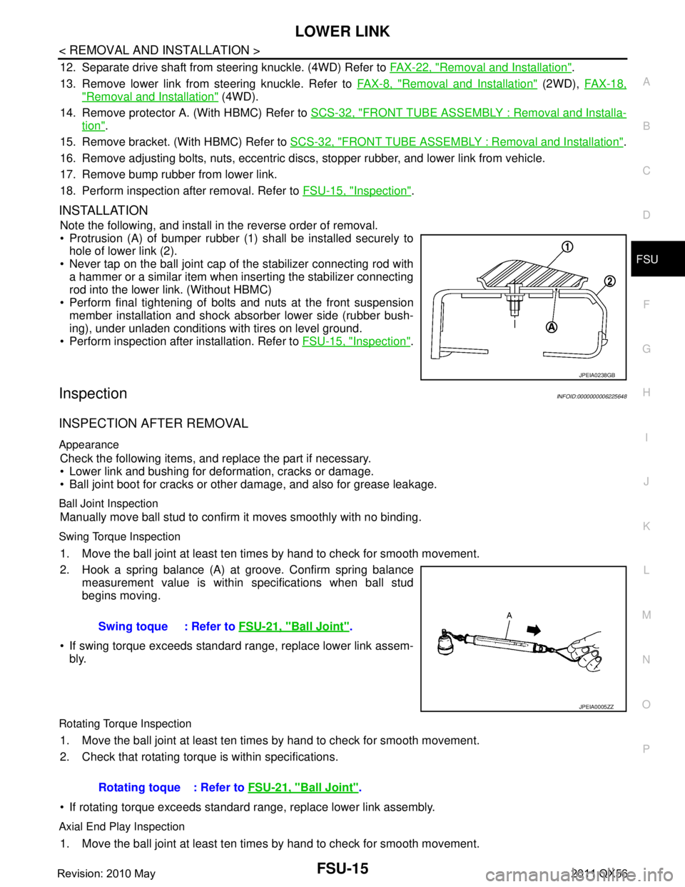
Protrusion (A) of bumper rubber (1) shall be installed securely to
hole of lower link (2).
Never tap on the ball joint cap of the stabilizer connecting rod with a hammer or a similar item when inserting the stabilizer connecting
rod into the lower link. (Without HBMC)
Perform final tightening of bolts and nuts at the front suspension member installation and shock absorber lower side (rubber bush-
ing), under unladen conditions with tires on level ground.
Perform inspection after installation. Refer to FSU-15, "
Inspection".
InspectionINFOID:0000000006225648
INSPECTION AFTER REMOVAL
Appearance
Check the following items, and replace the part if necessary.
Lower link and bushing for deformation, cracks or damage.
Ball joint boot for cracks or other damage, and also for grease leakage.
Ball Joint Inspection
Manually move ball stud to confirm it moves smoothly with no binding.
Swing Torque Inspection
1. Move the ball joint at least ten times by hand to check for smooth movement.
2. Hook a spring balance (A) at groove. Confirm spring balance
measurement value is within specifications when ball stud
begins moving.
If swing torque exceeds standard range, replace lower link assem- bly.
Rotating Torque Inspection
1. Move the ball joint at least ten times by hand to check for smooth movement.
2. Check that rotating torque is within specifications.
If rotating torque exceeds standard range, replace lower link assembly.
Axial End Play Inspection
1. Move the ball joint at least ten times by hand to check for smooth movement.
JPEIA0238GB
Swing toque : Refer to FSU-21, "Ball Joint".
JPEIA0005ZZ
Rotating toque : Refer to FSU-21, "Ball Joint".
Revision: 2010 May2011 QX56
Page 2960 of 5598
FSU-18
< REMOVAL AND INSTALLATION >
UPPER LINK
INSTALLATION
Note the following, and install in the reverse order of removal.
Perform final tightening of bolts and nuts at the vehicle installation position (rubber bushing), under unladenconditions with tires on level ground.
Perform inspection after installation. Refer to FSU-18, "
Inspection".
InspectionINFOID:0000000006225651
INSPECTION AFTER REMOVAL
Appearance
Check the following items, and replace the part if necessary.
Upper link and bushing for deformation, cracks or damage.
Ball joint boot for cracks or other damage, and also for grease leakage.
Ball Joint Inspection
Manually move ball stud to confirm it moves smoothly with no binding.
Swing Torque Inspection
1. Move the ball joint at least ten times by hand to check for smooth movement.
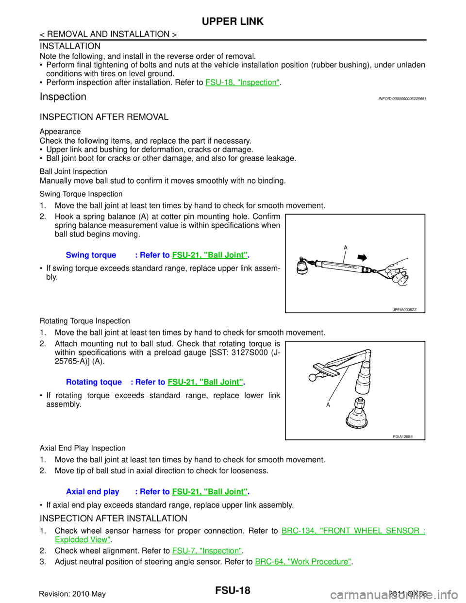
2. Hook a spring balance (A) at cotter pin mounting hole. Confirm
spring balance measurement value is within specifications when
ball stud begins moving.
If swing torque exceeds standard range, replace upper link assem- bly.
Rotating Torque Inspection
1. Move the ball joint at least ten times by hand to check for smooth movement.
2. Attach mounting nut to ball stud. Check that rotating torque is
within specifications with a preload gauge [SST: 3127S000 (J-
25765-A)] (A).
If rotating torque exceeds standard range, replace lower link assembly.
Axial End Play Inspection
1. Move the ball joint at least ten times by hand to check for smooth movement.
2. Move tip of ball stud in axial direction to check for looseness.
If axial end play exceeds standard range, replace upper link assembly.
INSPECTION AFTER INSTALLATION
1. Check wheel sensor harness for proper connection. Refer to BRC-134, "FRONT WHEEL SENSOR :
Exploded View".
2. Check wheel alignment. Refer to FSU-7, "
Inspection".
3. Adjust neutral position of steering angle sensor. Refer to BRC-64, "
Work Procedure".
Swing torque : Refer to
FSU-21, "
Ball Joint".
JPEIA0005ZZ
Rotating toque : Refer to FSU-21, "Ball Joint".
PDIA1258E
Axial end play : Refer to FSU-21, "Ball Joint".
Revision: 2010 May2011 QX56
Page 2969 of 5598
HOW TO USE THIS MANUALGI-5
< HOW TO USE THIS MANUAL >
C
DE
F
G H
I
J
K L
M B
GI
N
O P
SYMBOLS
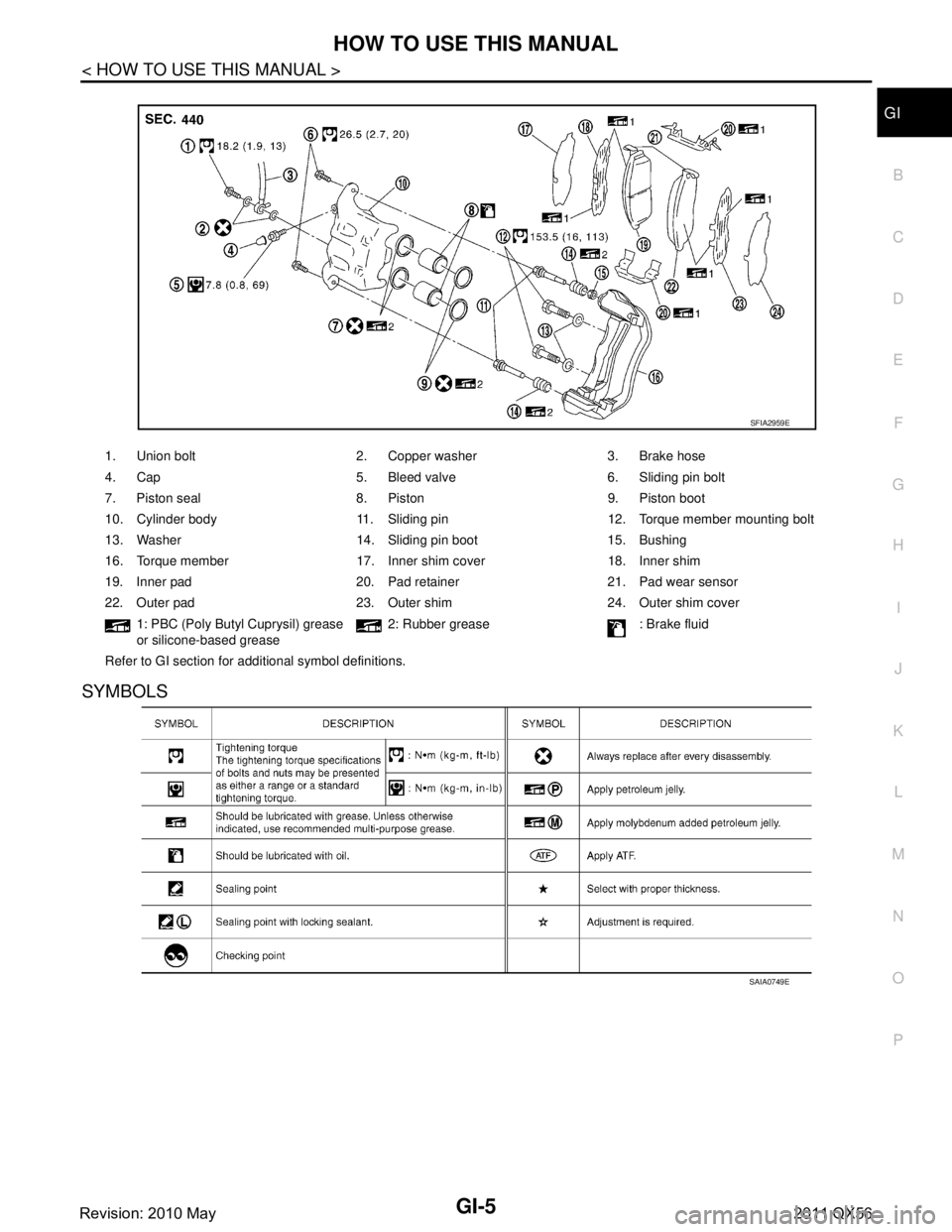
1. Union bolt 2. Copper washer 3. Brake hose
4. Cap 5. Bleed valve 6. Sliding pin bolt
7. Piston seal 8. Piston 9. Piston boot
10. Cylinder body 11. Sliding pin 12. Torque member mounting bolt
13. Washer 14. Sliding pin boot 15. Bushing
16. Torque member 17. Inner shim cover 18. Inner shim
19. Inner pad 20. Pad retainer 21. Pad wear sensor
22. Outer pad 23. Outer shim 24. Outer shim cover 1: PBC (Poly Butyl Cuprysil) grease
or silicone-based grease 2: Rubber grease : Brake fluid
Refer to GI section for additional symbol definitions.
SFIA2959E
SAIA0749E
Revision: 2010 May2011 QX56
Page 3677 of 5598
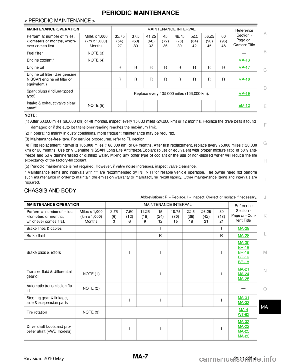
PERIODIC MAINTENANCEMA-7
< PERIODIC MAINTENANCE >
C
DE
F
G H
I
J
K L
M B
MA
N
O A
NOTE:
(1) After 60,000 miles (96,000 km) or 48 months, inspect every 15,000 miles (24,000 km) or 12 months. Replace the drive belts i
f found
damaged or if the auto belt tensioner reading reaches the maximum limit.
(2) If operating mainly in dusty conditions, more frequent maintenance may be required.
(3) Maintenance-free item. For service procedures, refer to FL section.
(4) First replacement interval is 105,000 miles (168,000 km) or 84 months. After first replacement, replace every 75,000 miles (120,000
km) or 60 months. Use only Genu ine NISSAN Long Life Antifreeze/Coo lant (blue) or equivalent with proper mixture ratio of 50% anti-
freeze and 50% demineralized or distilled water. Mixing any other type of coolant or the use of non-distilled water will reduce the life
expectancy of the factory-fill coolant.
(5) Periodic maintenance is not required. However, if valve noise increases, inspect valve clearance.
* Maintenance items and intervals with “*” are recommended by INFINITI for reliable vehicle operation. The owner need not perfo rm
such maintenance in order to maintain the emission warranty or manufacturer recall liability. Other maintenance items and inter vals are
required.
CHASSIS AND BODY
Abbreviations: R = Replace. I = Inspec t. Correct or replace if necessary.
Fuel filter NOTE (3) —
Engine coolant* NOTE (4) MA-13
Engine oil R R R R R R R RMA-17
Engine oil filter (Use genuine
NISSAN engine oil filter or
equivalent.)R R RRRRRR
MA-18
Spark plugs (Iridium-tipped
type)Replace every 105,000 miles (168,000 km).
MA-19
Intake & exhaust valve clear-
ance*NOTE (5)
EM-12
MAINTENANCE OPERATIONMAINTENANCE INTERVAL
Reference
Section -
Page or -
Content Title
Perform at number of miles,
kilometers or months, which-
ever comes first. Miles x 1,000
(km x 1,000)
Months 33.75
(54)
27 37.5
(60)
30 41.25
(66)
33 45
(72)
36 48.75
(78)
39 52.5
(84)
42 56.25
(90)
45 60
(96)
48
MAINTENANCE OPERATION MAINTENANCE INTERVAL
Reference
Section -
Page or - Con- tent Title
Perform at number of miles,
kilometers or months,
whichever comes first. Miles x 1,000
(km x 1,000)
Months 3.75
(6)
3 7.50
(12)
6 11 . 2 5
(18)
9 15
(24)
12 18.75
(30)
15 22.5
(36)
18 26.25
(42)
21 30
(48)
24
Brake lines & cables I I MA-28
Brake fluid R RMA-28
Brake pads & rotors I I I IMA-30
BR-16
BR-18
BR-16
BR-18
Transfer fluid & differential
gear oil
NOTE (1) I I MA-21MA-24
MA-25
Automatic transmission flu-
id
NOTE (2)
—
Steering gear & linkage,
axle & suspension parts IIII
MA-31
MA-32
Tire rotation NOTE (3) MA-4WT-63
Drive shaft boots and pro-
peller shaft (4WD models) IIII MA-33MA-22
MA-23
MA-23
Revision: 2010 May2011 QX56