Page 4207 of 5598
REAR DRIVE SHAFTRAX-11
< REMOVAL AND INSTALLATION >
CEF
G H
I
J
K L
M A
B
RAX
N
O P
REAR DRIVE SHAFT
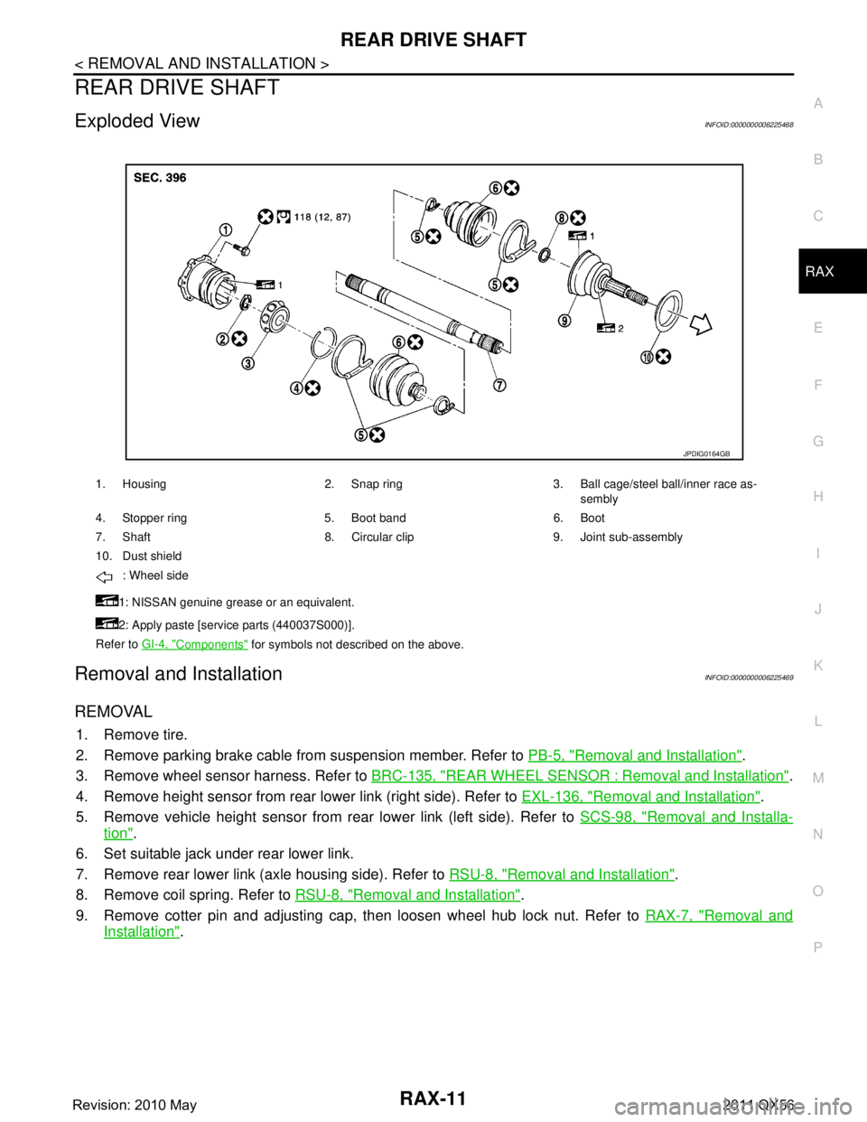
Exploded ViewINFOID:0000000006225468
Removal and InstallationINFOID:0000000006225469
REMOVAL
1. Remove tire.
2. Remove parking brake cable from suspension member. Refer to PB-5, "
Removal and Installation".
3. Remove wheel sensor harness. Refer to BRC-135, "
REAR WHEEL SENSOR : Removal and Installation".
4. Remove height sensor from rear lower link (right side). Refer to EXL-136, "
Removal and Installation".
5. Remove vehicle height sensor from rear lower link (left side). Refer to SCS-98, "
Removal and Installa-
tion".
6. Set suitable jack under rear lower link.
7. Remove rear lower link (axle housing side). Refer to RSU-8, "
Removal and Installation".
8. Remove coil spring. Refer to RSU-8, "
Removal and Installation".
9. Remove cotter pin and adjusting cap, then loosen wheel hub lock nut. Refer to RAX-7, "
Removal and
Installation".
1. Housing 2. Snap ring 3. Ball cage/steel ball/inner race as-
sembly
4. Stopper ring 5. Boot band 6. Boot
7. Shaft 8. Circular clip 9. Joint sub-assembly
10. Dust shield : Wheel side
1: NISSAN genuine grease or an equivalent.
2: Apply paste [service parts (440037S000)].
Refer to GI-4, "
Components" for symbols not described on the above.
JPDIG0164GB
Revision: 2010 May2011 QX56
Page 4209 of 5598
REAR DRIVE SHAFTRAX-13
< REMOVAL AND INSTALLATION >
CEF
G H
I
J
K L
M A
B
RAX
N
O P
2. Remove dust shield from drive shaft.
3. Remove boot bands and then remove boot from joint sub-assembly.
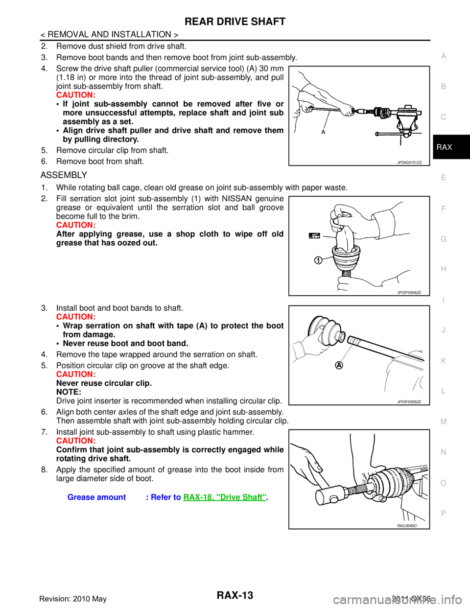
4. Screw the drive shaft puller (commercial service tool) (A) 30 mm (1.18 in) or more into the thread of joint sub-assembly, and pull
joint sub-assembly from shaft.
CAUTION:
If joint sub-assembly cannot be removed after five ormore unsuccessful attempts, replace shaft and joint sub
assembly as a set.
Align drive shaft puller and drive shaft and remove them by pulling directory.
5. Remove circular clip from shaft.
6. Remove boot from shaft.
ASSEMBLY
1. While rotating ball cage, clean old grease on joint sub-assembly with paper waste.
2. Fill serration slot joint sub-assembly (1) with NISSAN genuine grease or equivalent until the serration slot and ball groove
become full to the brim.
CAUTION:
After applying grease, use a shop cloth to wipe off old
grease that has oozed out.
3. Install boot and boot bands to shaft. CAUTION:
Wrap serration on shaft with tape (A) to protect the bootfrom damage.
Never reuse boot and boot band.
4. Remove the tape wrapped around the serration on shaft.
5. Position circular clip on groove at the shaft edge. CAUTION:
Never reuse circular clip.
NOTE:
Drive joint inserter is recommended when installing circular clip.
6. Align both center axles of the shaft edge and joint sub-assembly. Then assemble shaft with joint s ub-assembly holding circular clip.
7. Install joint sub-assembly to shaft using plastic hammer. CAUTION:
Confirm that joint sub-assembly is correctly engaged while
rotating drive shaft.
8. Apply the specified amount of grease into the boot inside from
large diameter side of boot.
JPDIG0151ZZ
JPDIF0008ZZ
Grease amount : Refer to RAX-18, "Drive Shaft".
JPDIF0009ZZ
RAC0049D
Revision: 2010 May2011 QX56
Page 4210 of 5598
RAX-14
< REMOVAL AND INSTALLATION >
REAR DRIVE SHAFT
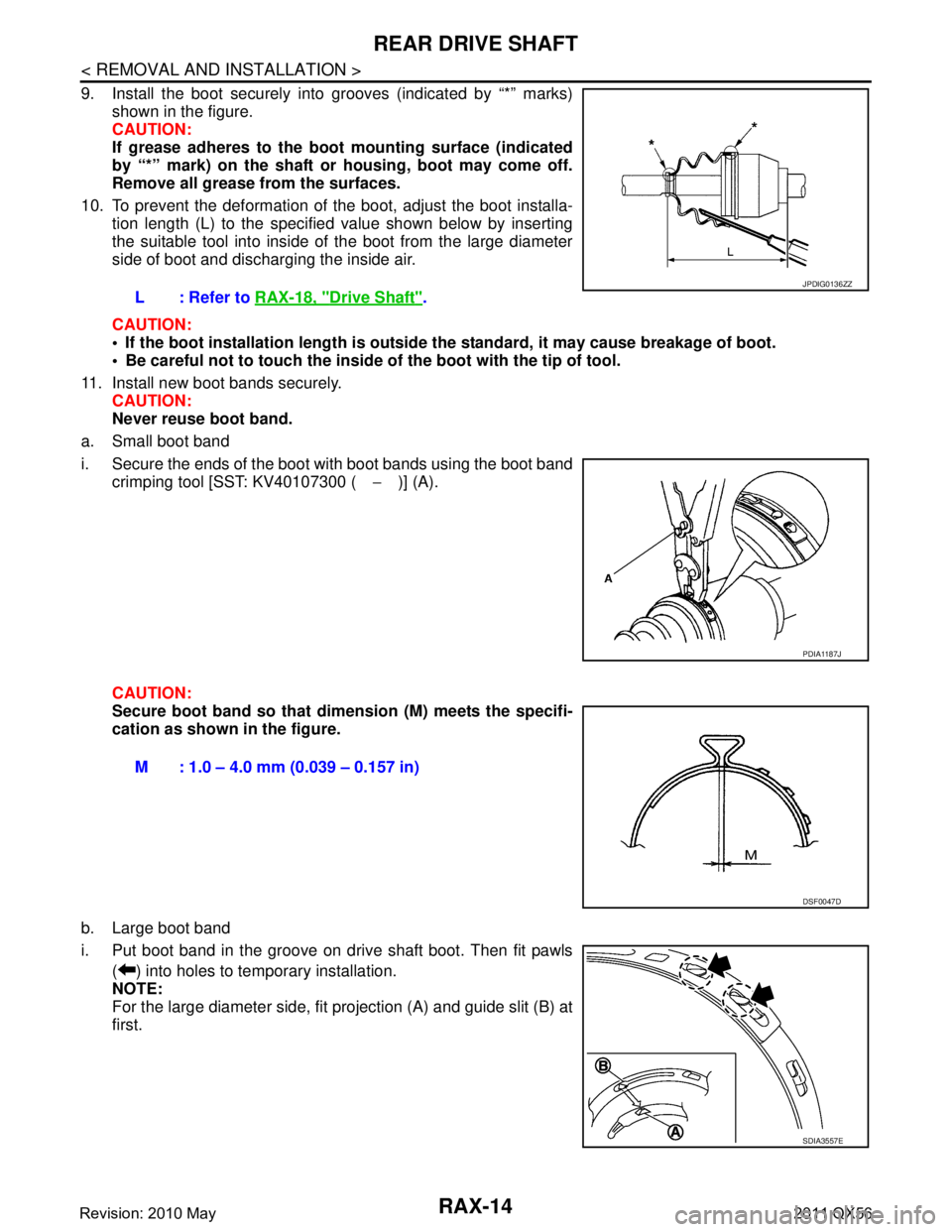
9. Install the boot securely into grooves (indicated by “*” marks)shown in the figure.
CAUTION:
If grease adheres to the boot mounting surface (indicated
by “*” mark) on the shaft or housing, boot may come off.
Remove all grease from the surfaces.
10. To prevent the deformation of the boot, adjust the boot installa- tion length (L) to the specified value shown below by inserting
the suitable tool into inside of the boot from the large diameter
side of boot and discharging the inside air.
CAUTION:
If the boot installation length is outsid e the standard, it may cause breakage of boot.
Be careful not to touch the inside of the boot with the tip of tool.
11. Install new boot bands securely. CAUTION:
Never reuse boot band.
a. Small boot band
i. Secure the ends of the boot with boot bands using the boot band crimping tool [SST: KV40107300 ( −)] (A).
CAUTION:
Secure boot band so that dimension (M) meets the specifi-
cation as shown in the figure.
b. Large boot band
i. Put boot band in the groove on drive shaft boot. Then fit pawls ( ) into holes to temporary installation.
NOTE:
For the large diameter side, fit projection (A) and guide slit (B) at
first.L: Refer to
RAX-18, "
Drive Shaft".
JPDIG0136ZZ
PDIA1187J
M : 1.0 – 4.0 mm (0.039 – 0.157 in)
DSF0047D
SDIA3557E
Revision: 2010 May2011 QX56
Page 4211 of 5598
REAR DRIVE SHAFTRAX-15
< REMOVAL AND INSTALLATION >
CEF
G H
I
J
K L
M A
B
RAX
N
O P
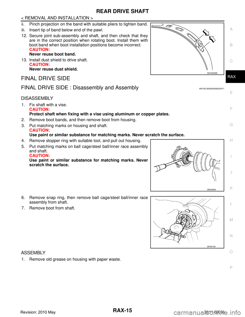
ii. Pinch projection on the band with suitable pliers to tighten band.
iii. Insert tip of band below end of the pawl.
12. Secure joint sub-assembly and shaft, and then check that they are in the correct position when rotating boot. Install them with
boot band when boot installation positions become incorrect.
CAUTION:
Never reuse boot band.
13. Install dust shield to drive shaft. CAUTION:
Never reuse dust shield.
FINAL DRIVE SIDE
FINAL DRIVE SIDE : Dis assembly and AssemblyINFOID:0000000006225471
DISASSEMBLY
1. Fix shaft with a vise.
CAUTION:
Protect shaft when fixing with a vi se using aluminum or copper plates.
2. Remove boot bands, and then remove boot from housing.
3. Put matching marks on housing and shaft. CAUTION:
Use paint or similar substance for matc hing marks. Never scratch the surface.
4. Remove stopper ring with suitable tool, and pull out housing.
5. Put matching marks on ball cage/steel ball/inner race assembly and shaft.
CAUTION:
Use paint or similar substance for matching marks. Never
scratch the surface.
6. Remove snap ring, then remove ball cage/steel ball/inner race assembly from shaft.
7. Remove boot from shaft.
ASSEMBLY
1. Remove old grease on housing with paper waste.
SDIA3558E
SRA249A
SFA514A
Revision: 2010 May2011 QX56
Page 4212 of 5598
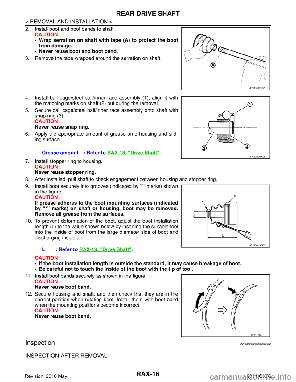
RAX-16
< REMOVAL AND INSTALLATION >
REAR DRIVE SHAFT
2. Install boot and boot bands to shaft.CAUTION:
Wrap serration on shaft with tape (A) to protect the bootfrom damage.
Never reuse boot and boot band.
3. Remove the tape wrapped around the serration on shaft.
4. Install ball cage/steel ball/inner race assembly (1), align it with the matching marks on shaft (2) put during the removal.
5. Secure ball cage/steel ball/inner race assembly onto shaft with snap ring (3).
CAUTION:
Never reuse snap ring.
6. Apply the appropriate amount of grease onto housing and slid- ing surface.
7. Install stopper ring to housing. CAUTION:
Never reuse stopper ring.
8. After installed, pull shaft to check engagement between housing and stopper ring.
9. Install boot securely into grooves (indicated by “*” marks) shown in the figure.
CAUTION:
If grease adheres to the boot mounting surfaces (indicated
by “*” marks) on shaft or housing, boot may be removed.
Remove all grease from the surfaces.
10. To prevent deformation of the boot, adjust the boot installation
length (L) to the value shown below by inserting the suitable tool
into the inside of boot from the large diameter side of boot and
discharging inside air.
CAUTION:
If the boot installation length is outsid e the standard, it may cause breakage of boot.
Be careful not to touch the inside of the boot with the tip of tool.
11. Install boot bands securely as shown in the figure. CAUTION:
Never reuse boot band.
12. Secure housing and shaft, and then check that they are in the correct position when rotating boot. Install them with boot band
when the mounting positi ons become incorrect.
CAUTION:
Never reuse boot band.
InspectionINFOID:0000000006225472
INSPECTION AFTER REMOVAL
JPDIF0009ZZ
Grease amount : Refer to RAX-18, "Drive Shaft".
L: Refer to RAX-18, "
Drive Shaft".
JPDIG0004ZZ
JPDIG0137ZZ
PDIA1188J
Revision: 2010 May2011 QX56
Page 4213 of 5598
REAR DRIVE SHAFTRAX-17
< REMOVAL AND INSTALLATION >
CEF
G H
I
J
K L
M A
B
RAX
N
O P
Move joint up/down, left/right, and in the axial directi on. Check for any rough movement or significant loose-
ness.
Check boot for cracks or other damage, and also for grease leak-
age.
If a malfunction is found, disassem ble drive shaft, and then replace
with new one.
INSPECTION AFTER INSTALLATION
1. Check wheel alignment. Refer to RSU-6, "Inspection".
2. Adjust neutral position of steering angle sensor. Refer to BRC-64, "
Work Procedure".
3. Adjust levelizer adjustment of height sensor. Refer to EXL-61, "
LEVELIZER ADJUSTMENT : Special
Repair Requirement".
4. Check standard vehicle height setting of vehicle height sensor. Refer to SCS-67, "
Work Procedure".
RAA0030D
Revision: 2010 May2011 QX56
Page 4214 of 5598
RAX-18
< SERVICE DATA AND SPECIFICATIONS (SDS)
SERVICE DATA AND SPECIFICATIONS (SDS)
SERVICE DATA AND SPECIFICATIONS (SDS)
SERVICE DATA AND SPECIFICATIONS (SDS)
Wheel Hub and Bearing AssemblyINFOID:0000000006225473
Drive ShaftINFOID:0000000006225474
Item Standard
Axial end play 0.05 mm (0.002 in) or less
ItemStandard
Wheel side Final drive side
Grease quantity 145 – 165 g (5.11 – 5.82 oz) 175 – 195 g (6.17 – 6.88 oz)
Boots installed length 134.5 mm (5.30 in) 147.9 mm (5.82 in)
Revision: 2010 May2011 QX56
Page 4260 of 5598
REAR SUSPENSION ASSEMBLYRSU-5
< PERIODIC MAINTENANCE >
C
DF
G H
I
J
K L
M A
B
RSU
N
O P
PERIODIC MAINTENANCE
REAR SUSPENSION ASSEMBLY
InspectionINFOID:0000000006225660
MOUNTING INSPECTION
Check the mounting conditions (looseness, backlash) of each component and component conditions (wear,
damage) are normal.
BALL JOINT AXIAL END PLAY
Measure axial end play by placing and moving up/down with an iron bar or equivalent between suspension
arm or front lower link and axle assembly.
CAUTION:
• Never depress brake pedal when measuring.
Never perform with tires on level ground.
Be careful not to damage ball joint boot.
SHOCK ABSORBER
Check for oil leakage and damage. Replace it if necessary. Axial end play : Refer to
RSU-20, "
Ball Joint".
Revision: 2010 May2011 QX56