2011 INFINITI QX56 clutch
[x] Cancel search: clutchPage 2978 of 5598

GI-14
< HOW TO USE THIS MANUAL >
ABBREVIATIONS
ABBREVIATIONS
Abbreviation ListINFOID:0000000006280882
The following ABBREVIATIONS are used:
A
B
C
D
ABBREVIATION DESCRIPTION
A/C Air conditioner
A/C Air conditioning
A/F sensor Air fuel ratio sensor A/T Automatic transaxle/transmission
ABS Anti-lock braking system
ACCS Advance climate control system ACL Air cleaner
AP Accelerator pedal
APP Accelerator pedal position ATF Automatic transmission fluid AV Audio visual
AWD All wheel drive
ABBREVIATION DESCRIPTION BARO Barometric pressureBCM Body control module
BLSD Brake limited slip differential BPP Brake pedal positionBSI Blind spot intervention
BSW Blind spot warning
ABBREVIATION DESCRIPTION CKP Crankshaft positionCL Closed loop
CMP Camshaft position CPP Clutch pedal positionCTP Closed throttle position
CVT Continuously Variable transaxle/transmission
ABBREVIATION DESCRIPTION D
1Drive range first gear
D
2Drive range second gear
D
3Drive range third gear
D
4Drive range fourth gear
DCA Distance control assist DFI Direct fuel injection system
DLC Data link connector
DTC Diagnostic trouble code
Revision: 2010 May2011 QX56
Page 3057 of 5598

HA-1
VENTILATION, HEATER & AIR CONDITIONER
C
DE
F
G H
J
K L
M
SECTION HA
A
B
HA
N
O P
CONTENTS
HEATER & AIR CONDITIONING SYSTEM
PRECAUTION ................ ...............................3
PRECAUTIONS .............................................. .....3
Precaution for Supplemental Restraint System
(SRS) "AIR BAG" and "SEAT BELT PRE-TEN-
SIONER" ............................................................. ......
3
Precaution Necessary for Steering Wheel Rota-
tion after Battery Disconnect .....................................
3
Precaution for Procedure without Cowl Top Cover ......4
Precautions For Refrigerant System Service ............4
Service Equipment ....................................................6
PREPARATION ............................................9
PREPARATION .............................................. .....9
Special Service Tool ........................................... ......9
Commercial Service Tool ........................................12
Sealant or/and Lubricant .........................................12
SYSTEM DESCRIPTION .............................13
COMPONENT PARTS ................................... ....13
Component Parts Location .................................. ....13
Component Description ...........................................13
SYSTEM .............................................................14
System Diagram .................................................. ....14
System Description .................................................14
BASIC INSPECTION ...................................16
DIAGNOSIS AND REPAIR WORKFLOW ..... ....16
Work Flow ........................................................... ....16
REFRIGERANT ..................................................18
Description .......................................................... ....18
Leak Test ................................................................18
Recycle Refrigerant .................................................20
Charge Refrigerant ..................................................20
LUBRICANT ................................................... ....22
Description .......................................................... ....22
Inspection ............................................................ ....22
Perform Lubricant Return Operation .......................22
Lubricant Adjusting Procedure for Components
Replacement Except Compressor ...........................
22
Lubricant Adjusting Procedure for Compressor
Replacement ...........................................................
23
PERFORMANCE TEST ....................................25
Inspection ................................................................25
SYMPTOM DIAGNOSIS ..............................27
REFRIGERATION SYSTEM SYMPTOMS ........27
Trouble Diagnosis For Unusual Pressure ............ ....27
Symptom Table .......................................................27
NOISE ................................................................29
Symptom Table .......................................................29
REMOVAL AND INSTALLATION ...............30
COMPRESSOR .................................................30
Exploded View ..................................................... ....30
COMPRESSOR ..........................................................30
COMPRESSOR : Removal and Installation ............30
MAGNET CLUTCH ................................................ ....31
MAGNET CLUTCH : Removal and Installation of
Compressor Clutch ..................................................
31
Inspection ................................................................32
COOLER PIPE AND HOSE ..............................33
Exploded View .........................................................33
HIGH-PRESSURE FLEXIBLE HOSE ........................34
HIGH-PRESSURE FLEXIBLE HOSE : Removal
and Installation .................................................... ....
34
LOW-PRESSURE FLEXIBLE HOSE ..................... ....35
LOW-PRESSURE FLEXIBLE HOSE : Removal
and Installation ........................................................
35
HIGH-PRESSURE PIPE ............................................35
Revision: 2010 May2011 QX56
Page 3061 of 5598
PRECAUTIONSHA-5
< PRECAUTION >
C
DE
F
G H
J
K L
M A
B
HA
N
O P
- Never allow lubricant (A/C System Oil Type R) to come in contact with styrene foam parts. Damage
may result.
REFRIGERANT CONNECTION
A new type refrigerant connection has been introduced to a ll refrigerant lines except the following location.
Expansion valve to evaporator
Refrigerant pressure sensor to liquid tank
WARNING:
Check that all refrigerant is discharged into the recycling equipment and the pressure in the system is
less than atmospheric pressure. Then gradually loo sen the discharge side hose fitting and remove it.
CAUTION:
Observe the following when replacing or cleaning refrigerant cycle components.
Store it in the same way at it is when mounted on the car when the compressor is removed. Failure
to do so will cause lubricant to enter the low-pressure chamber.
Use always a torque wrench and a b ack-up wrench when connecting tubes.
Plug immediately all openings to prevent entry of dust and mois ture after disconnecting tubes.
Connect the pipes at the final stag e of the operation when installing an air conditioner in the vehicle.
Never remove the seal caps of pipes and other compon ents until just before required for connection.
Allow components stored in cool areas to warm to working area temperature before removing seal
caps. This prevents condensation from forming inside A/C components.
Remove thoroughly moisture from the refriger ation system before charging the refrigerant.
Replace always used O-rings.
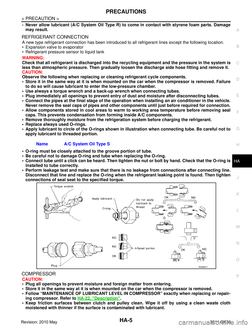
Apply lubricant to circle of th e O-rings shown in illustration when connecting tube. Be careful not to
apply lubricant to threaded portion.
O-ring must be closely attached to the groove portion of tube.
Be careful not to damage O-ring and tube when replacing the O-ring.
Connect tube until a click can be heard. Then tighten the nut or bolt by hand. Check that the O-ring is
installed to tube correctly.
Perform leakage test and make sure that there is no leakage from connections after connecting line.
Disconnect that line and replace the O-ring when the refrigerant leaking point is found. Then tighten
connections of seal seat to the specified torque.
COMPRESSOR
CAUTION:
Plug all openings to prevent moisture and foreign matter from entering.
Store it in the same way at it is when moun ted on the car when the compressor is removed.
Follow “MAINTENANCE OF LUBRICANT LEVEL IN CO MPRESSOR” exactly when replacing or repair-
ing compressor. Refer to HA-22, "
Description".
Keep friction surfaces between clutch and pulley cl ean. Wipe it off by using a clean waste cloth
moistened with thinner if the surface is contaminated with lubricant.
Name A/C System Oil Type S
RHA861F
Revision: 2010 May2011 QX56
Page 3062 of 5598

HA-6
< PRECAUTION >
PRECAUTIONS
Turn the compressor shaft by hand more than five turns in both directions after compressor service
operation. This distributes equall y lubricant inside the compressor. Let the engine idle and operate
the compressor for one hour after the compressor is installed.
Apply voltage to the new one and check for norma l operation after replacing the compressor magnet
clutch.
LEAK DETECTION DYE
CAUTION:
The A/C system contains a fluorescent leak detect ion dye used for locating refrigerant leakages. An
ultraviolet (UV) lamp is required to il luminate the dye when inspecting for leakages.
Wear always fluorescence enhancing UV safety goggles to protect eyes and enhance the visibility of
the fluorescent dye.
The fluorescent dye leak detector is not a replacem ent for an electrical leak detector. The fluorescent
dye leak detector should be used in conjunction with an electrical leak detector to pin-point refriger-
ant leakages.
Read and follow all manufacture’ s operating instructions and precau tions prior to performing the
work for the purpose of safet y and customer’s satisfaction.
A compressor shaft seal should not necessarily be repaired because of dye seepage. The compres-
sor shaft seal should only be repaired after conf irming the leakage with an electrical leak detector.
Remove always any remaining dye from the leakage area after repairs are completed to avoid a mis-
diagnosis during a future service.
Never allow dye to come into contact with painted body panels or interior components. Clean imme-
diately with the approved dye cl eaner if dye is spilled. Fluorescent dye left on a surface for an
extended period of time cannot be removed.
Never spray the fluorescent dye cleaning agent on hot surfaces (eng ine exhaust manifold, etc.).
Never use more than one refrigerant dye bottle [1/4 ounce (7.4 cc)] per A/C system.
Leak detection dyes for HFC-134a (R-134a) and CFC- 12 (R-12) A/C systems are different. Never use
HFC-134a (R-134a) leak detection dye in CFC-12 (R- 12) A/C system, or CFC-12 (R-12) leak detection
dye in HFC-134a (R-134a) A/C system, or A/C system damage may result.
The fluorescent properties of the dye remains fo r three or more years unless a compressor malfunc-
tion occurs.
NOTE:
Identification
Vehicles with factory installed fluorescent dye have a green label.
Vehicles without factory installed fluorescent dye have a blue label.
Service EquipmentINFOID:0000000006276140
RECOVERY/RECYCLING RECHARGING EQUIPMENT
Be certain to follow the manufacturer’s instructions for machine operation and machine maintenance. Never
introduce any refrigerant other than that specified into the machine.
ELECTRICAL LEAK DETECTOR
Be certain to follow the manufacturer’s instruct ions for tester operation and tester maintenance.
VACUUM PUMP
Revision: 2010 May2011 QX56
Page 3079 of 5598
LUBRICANTHA-23
< BASIC INSPECTION >
C
DE
F
G H
J
K L
M A
B
HA
N
O P
Lubricant Adjusting Procedur e for Compressor ReplacementINFOID:0000000006276157
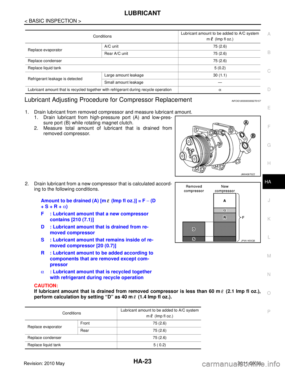
1. Drain lubricant from removed compressor and measure lubricant amount.
1. Drain lubricant from high-pressure port (A) and low-pres-
sure port (B) while rotating magnet clutch.
2. Measure total amount of lubricant that is drained from removed compressor.
2. Drain lubricant from a new compressor that is calculated accord- ing to the following conditions.
CAUTION:
If lubricant amount that is drained from removed compressor is less than 60 m (2.1 Imp fl oz.),
perform calculation by setting “D” as 40 m (1.4 Imp fl oz.).
Conditions Lubricant amount to be added to A/C system
m (Imp fl oz.)
Replace evaporator A/C unit 75 (2.6)
Rear A/C unit 75 (2.6)
Replace condenser 75 (2.6)
Replace liquid tank 5 (0.2)
Refrigerant leakage is detected Large amount leakage 30 (1.1)
Small amount leakage —
Lubricant amount that is recycled together with refrigerant during recycle operation α
JMIIA0675ZZ
Amount to be drained (A) [m (Imp fl oz.)] = F − (D
+ S + R + α)
F : Lubricant amount that a new compressor contains [210 (7.1)]
D : Lubricant amount that is drained from re- moved compressor
S : Lubricant amount that remains inside of re-
moved compressor [20 (0.7)]
R : Lubricant amount to be added according to components that are removed except com-
pressor
α : Lubricant amount that is recycled together
with refrigerant during recycle operation
Conditions Lubricant amount to be added to A/C system
m (Imp fl oz.)
Replace evaporator Front 75 (2.6)
Rear 75 (2.6)
Replace condenser 75 (2.6)
Replace liquid tank 5 ( 0.2)
JPIIA1455GB
Revision: 2010 May2011 QX56
Page 3085 of 5598
NOISEHA-29
< SYMPTOM DIAGNOSIS >
C
DE
F
G H
J
K L
M A
B
HA
N
O P
NOISE
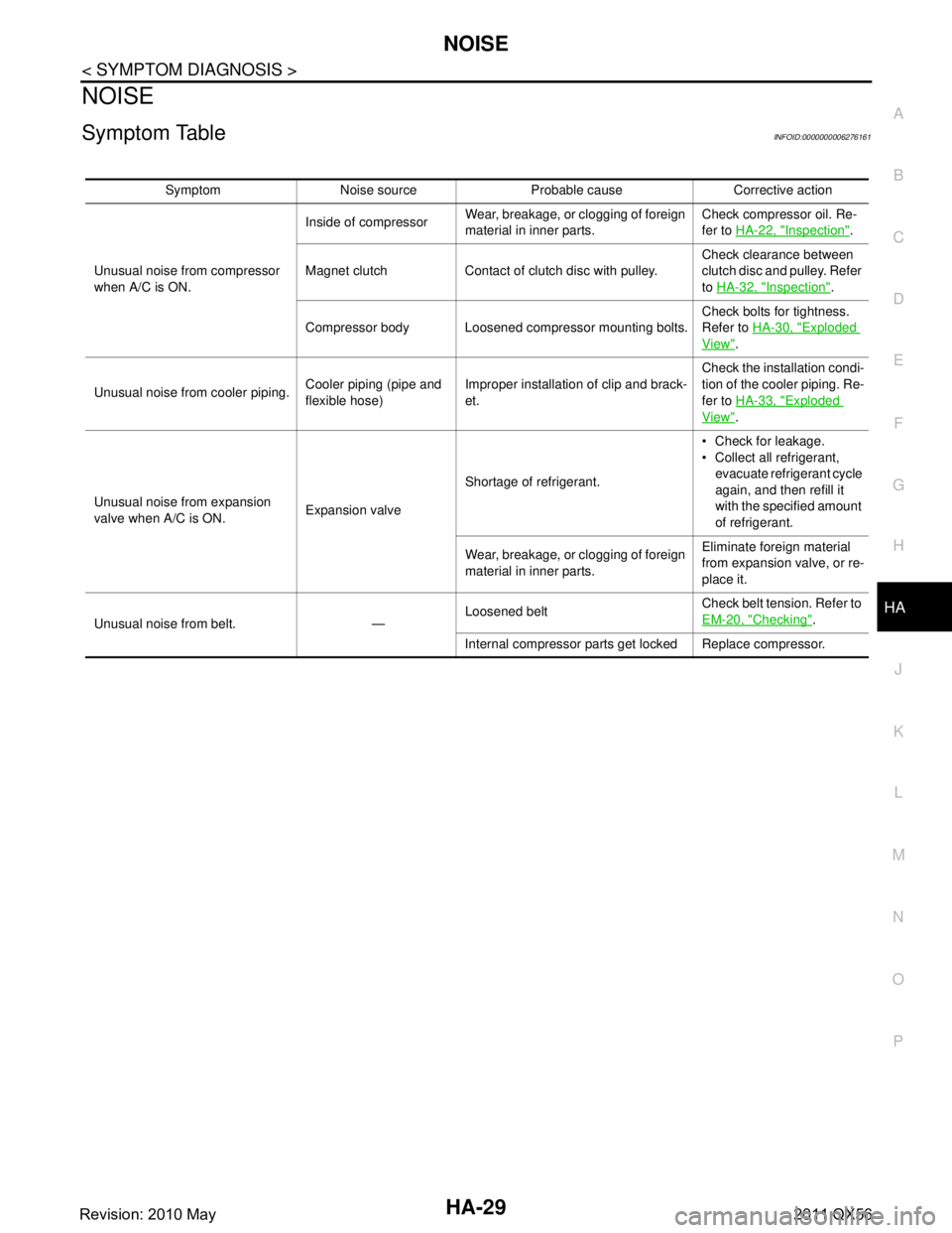
Symptom TableINFOID:0000000006276161
Symptom Noise source Probable cause Corrective action
Unusual noise from compressor
when A/C is ON. Inside of compressor
Wear, breakage, or clogging of foreign
material in inner parts. Check compressor oil. Re-
fer to
HA-22, "
Inspection".
Magnet clutch Contact of clutch disc with pulley. Check clearance between
clutch disc and pulley. Refer
to
HA-32, "
Inspection".
Compressor body Loosened compressor mounting bolts. Check bolts for tightness.
Refer to
HA-30, "
Exploded
View".
Unusual noise from cooler piping. Cooler piping (pipe and
flexible hose)Improper installation of clip and brack-
et. Check the installation condi-
tion of the cooler piping. Re-
fer to
HA-33, "
Exploded
View".
Unusual noise from expansion
valve when A/C is ON. Expansion valveShortage of refrigerant. Check for leakage.
Collect all refrigerant,
evacuate refrigerant cycle
again, and then refill it
with the specified amount
of refrigerant.
Wear, breakage, or clogging of foreign
material in inner parts. Eliminate foreign material
from expansion valve, or re-
place it.
Unusual noise from belt. — Loosened belt
Check belt tension. Refer to
EM-20, "
Checking".
Internal compressor parts ge t locked Replace compressor.
Revision: 2010 May2011 QX56
Page 3086 of 5598
HA-30
< REMOVAL AND INSTALLATION >
COMPRESSOR
REMOVAL AND INSTALLATION
COMPRESSOR
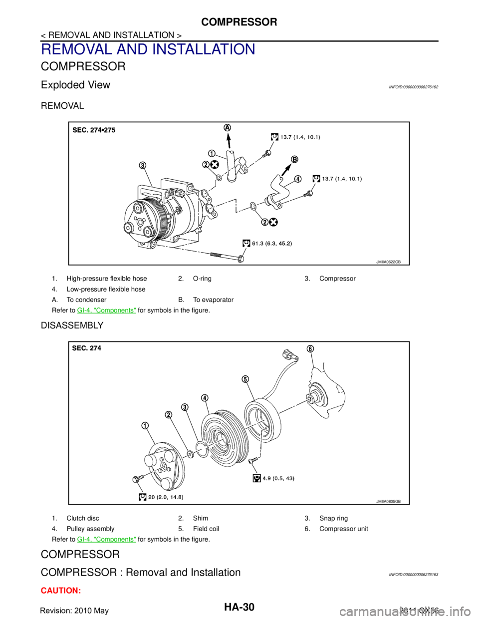
Exploded ViewINFOID:0000000006276162
REMOVAL
DISASSEMBLY
COMPRESSOR
COMPRESSOR : Removal and InstallationINFOID:0000000006276163
CAUTION:
1. High-pressure flexible hose 2. O-ring 3. Compressor
4. Low-pressure flexible hose
A. To condenser B. To evaporator
Refer to GI-4, "
Components" for symbols in the figure.
JMIIA0622GB
1. Clutch disc 2. Shim 3. Snap ring
4. Pulley assembly 5. Field coil 6. Compressor unit
Refer to GI-4, "
Components" for symbols in the figure.
JMIIA0805GB
Revision: 2010 May2011 QX56
Page 3087 of 5598
COMPRESSORHA-31
< REMOVAL AND INSTALLATION >
C
DE
F
G H
J
K L
M A
B
HA
N
O P
Perform lubricant return operati on before each refrigeration system disassembly. However, if a large
amount of refrigerant or lubricant is detected, n ever perform lubricant return operation. Refer to HA-
22, "Perform Lubricant Return Operation".
REMOVAL
1. Use a refrigerant collecting equipment (for HF C-134a) to discharge the refrigerant. Refer to HA-20, "Recy-
cle Refrigerant".
2. Remove air cleaner. Refer to EM-27, "
Removal and Installation".
3. Remove mounting bolts, and then disconnect low-pressure flexible hose and high-pressure flexible hose from the compressor.
CAUTION:
Cap or wrap the joint of the A/C piping and comp ressor with suitable material such as vinyl tape to
avoid the entry of air.
4. Remove front under cover. Refer to EXT-25, "
Exploded View".
5. Remove drive belt. Refer to EM-20, "
Removal and Installation".
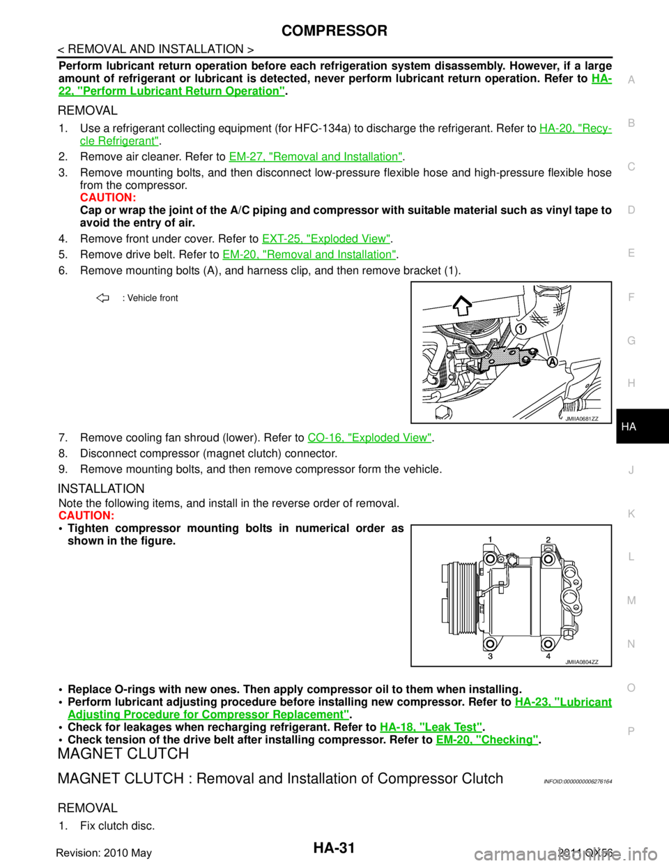
6. Remove mounting bolts (A), and harness clip, and then remove bracket (1).
7. Remove cooling fan shroud (lower). Refer to CO-16, "
Exploded View".
8. Disconnect compressor (magnet clutch) connector.
9. Remove mounting bolts, and then remove compressor form the vehicle.
INSTALLATION
Note the following items, and install in the reverse order of removal.
CAUTION:
Tighten compressor mounting bolts in numerical order as shown in the figure.
Replace O-rings with new ones. Then apply compressor oil to them when installing.
Perform lubricant adjusting procedure befo re installing new compressor. Refer to HA-23, "
Lubricant
Adjusting Procedure for Compressor Replacement".
Check for leakages when recharging refrigerant. Refer to HA-18, "
Leak Test".
Check tension of the drive belt afte r installing compressor. Refer to EM-20, "
Checking".
MAGNET CLUTCH
MAGNET CLUTCH : Removal and Inst allation of Compressor ClutchINFOID:0000000006276164
REMOVAL
1. Fix clutch disc.
: Vehicle front
JMIIA0681ZZ
JMIIA0804ZZ
Revision: 2010 May2011 QX56