2011 INFINITI QX56 check engine light
[x] Cancel search: check engine lightPage 2357 of 5598
![INFINITI QX56 2011 Factory Service Manual
P0451 EVAP CONTROL SYSTEM PRESSURE SENSOREC-333
< DTC/CIRCUIT DIAGNOSIS > [VK56VD]
C
D
E
F
G H
I
J
K L
M A
EC
NP
O
P0451 EVAP CONTROL SYSTEM
PRESSURE SENSOR
DTC LogicINFOID:0000000006288316
DTC DETE INFINITI QX56 2011 Factory Service Manual
P0451 EVAP CONTROL SYSTEM PRESSURE SENSOREC-333
< DTC/CIRCUIT DIAGNOSIS > [VK56VD]
C
D
E
F
G H
I
J
K L
M A
EC
NP
O
P0451 EVAP CONTROL SYSTEM
PRESSURE SENSOR
DTC LogicINFOID:0000000006288316
DTC DETE](/manual-img/42/57033/w960_57033-2356.png)
P0451 EVAP CONTROL SYSTEM PRESSURE SENSOREC-333
< DTC/CIRCUIT DIAGNOSIS > [VK56VD]
C
D
E
F
G H
I
J
K L
M A
EC
NP
O
P0451 EVAP CONTROL SYSTEM
PRESSURE SENSOR
DTC LogicINFOID:0000000006288316
DTC DETECTION LOGIC
DTC CONFIRMATION PROCEDURE
1.PRECONDITIONING
1. Turn ignition switch OFF and wait at least 10 seconds.
2. Turn ignition switch ON.
3. Turn ignition switch OFF and wait at least 10 seconds.
>> GO TO 2.
2.PERFORM DTC CONFIRMATION PROCEDURE
1. Start engine and wait at least 40 seconds. NOTE:
Do not depress accelerator pedal even slightly.
2. Check 1st trip DTC.
Is 1st trip DTC detected?
YES >> Proceed to EC-333, "Diagnosis Procedure".
NO >> INSPECTION END
Diagnosis ProcedureINFOID:0000000006288317
1.CHECK EVAP CONTRO L SYSTEM PRESSURE SENSOR CONNECTOR
1. Disconnect EVAP control system pressure sensor harness connector.
2. Check that water is not inside connectors.
Is the inspection result normal?
YES >> GO TO 2.
NO >> Repair or replace harness connector.
2.CHECK EVAP CONTROL SYS TEM PRESSURE SENSOR POWER SUPPLY CIRCUIT
1. Turn ignition switch ON.
2. Check the voltage between EVAP control system pressure sensor harness connector and ground.
DTC No. Trouble diagnosis name
(Trouble diagnosis con- tent) DTC detecting condition Possible cause
P0451 EVAP SYS PRES SEN
(EVAP control system
pressure sensor perfor-
mance) ECM detects a sloshing signal
from the EVAP control system
pressure sensor (EVAP control system pressure sensor circuit is shorted.)
Harness or connectors
(Battery current sensor circuit is open or shorted.)
(Accelerator pedal position sensor 2 circuit is shorted.)
[Camshaft position sensor (bank 1) circuit is shorted.]
(Crankshaft position sensor circuit is shorted.)
(Refrigerant pressure sensor circuit is shorted.)
EVAP control system pressure sensor
Battery current sensor
Accelerator pedal position sensor
Camshaft position sensor (bank 1)
Crankshaft position sensor
Refrigerant pressure sensor
EVAP control system
pressure sensor Ground Voltage (V)
Connector Terminal
C17 3 Ground Approx. 5 V
Revision: 2010 May2011 QX56
Page 2567 of 5598

PRECAUTIONSEM-5
< PRECAUTION >
C
DE
F
G H
I
J
K L
M A
EM
NP
O
Avoid damaging sliding or mating surfaces. Completely re
move foreign materials such as cloth lint or dust.
Before assembly, oil sliding surfaces well.
Release air within route when refilling after draining engine coolant.
After repairing, start engine and increase engine speed to check engine coolant, fuel, engine oil, and
exhaust gases for leakage.
Parts Requiring Angle TighteningINFOID:0000000006289515
Use angle wrench [SST: KV10112100 (BT8653-A)] for the final tightening of the following engine parts:
- Cylinder head bolts
- Main bearing cap bolts
- Main bearing cap sub bolts
- Connecting rod cap bolts
- Crankshaft pulley bolt (No angle wrench is required as the bolt flange is provided with notches for angletightening)
Ensure thread and seat surfaces are clean and coated with engine oil.
Precaution for Liquid GasketINFOID:0000000006289516
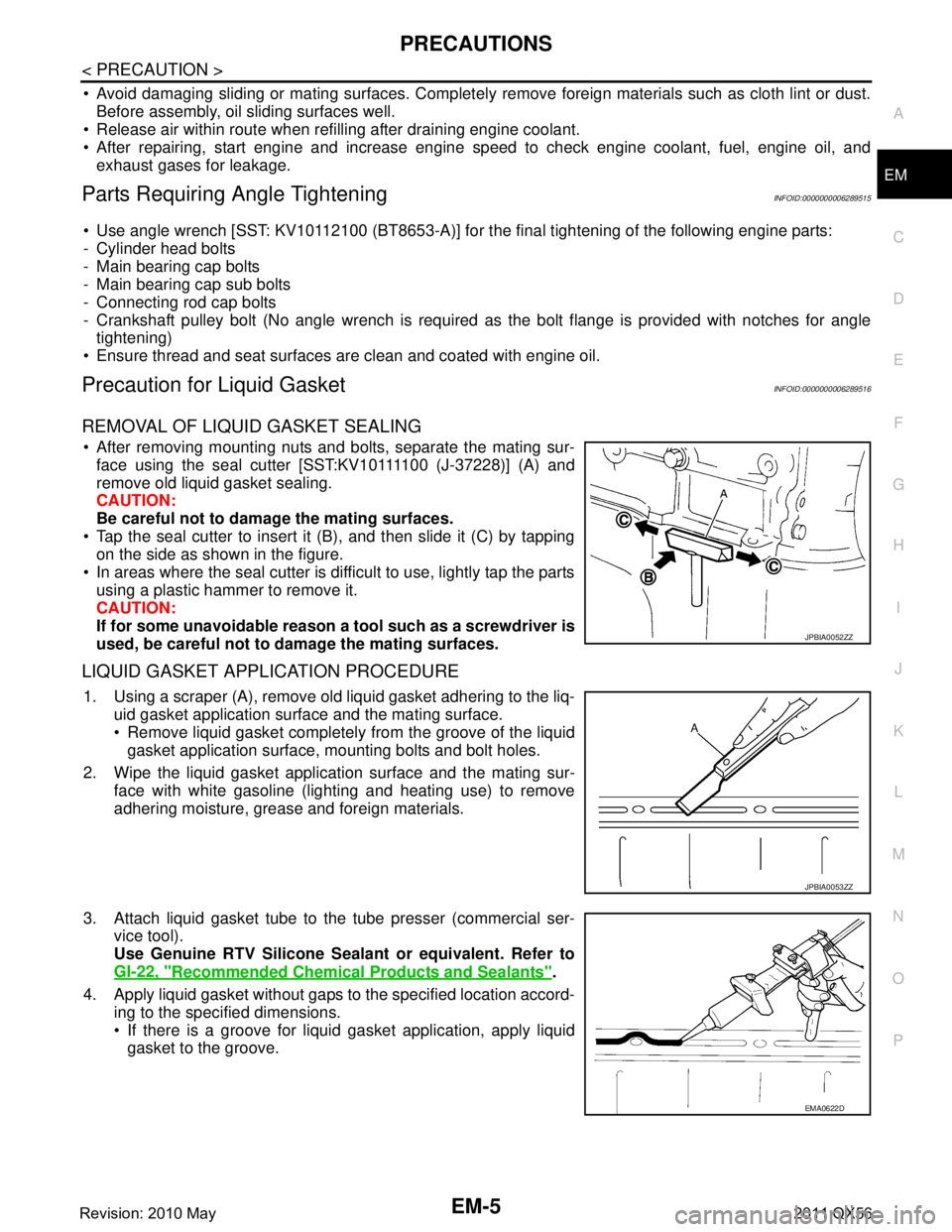
REMOVAL OF LIQUID GASKET SEALING
After removing mounting nuts and bolts, separate the mating sur- face using the seal cutter [SST:KV10111100 (J-37228)] (A) and
remove old liquid gasket sealing.
CAUTION:
Be careful not to damage the mating surfaces.
Tap the seal cutter to insert it (B), and then slide it (C) by tapping on the side as shown in the figure.
In areas where the seal cutter is difficult to use, lightly tap the parts using a plastic hammer to remove it.
CAUTION:
If for some unavoidable reason a tool such as a screwdriver is
used, be careful not to damage the mating surfaces.
LIQUID GASKET APPLICATION PROCEDURE
1. Using a scraper (A), remove old liquid gasket adhering to the liq- uid gasket application surface and the mating surface.
Remove liquid gasket completely from the groove of the liquidgasket application surface, mounting bolts and bolt holes.
2. Wipe the liquid gasket application surface and the mating sur- face with white gasoline (lighting and heating use) to remove
adhering moisture, grease and foreign materials.
3. Attach liquid gasket tube to the tube presser (commercial ser- vice tool).
Use Genuine RTV Silicone Seal ant or equivalent. Refer to
GI-22, "
Recommended Chemical Products and Sealants".
4. Apply liquid gasket without gaps to the specified location accord- ing to the specified dimensions.
If there is a groove for liquid gasket application, apply liquidgasket to the groove.
JPBIA0052ZZ
JPBIA0053ZZ
EMA0622D
Revision: 2010 May2011 QX56
Page 2608 of 5598

EM-46
< REMOVAL AND INSTALLATION >
HIGH PRESSURE FUEL PUMP AND FUEL HOSE
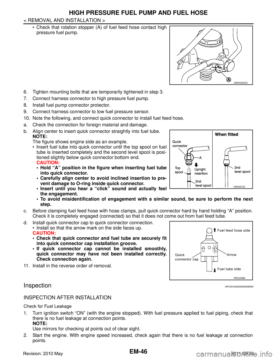
Check that rotation stopper (A) of fuel feed hose contact highpressure fuel pump.
6. Tighten mounting bolts that are temporarily tightened in step 3.
7. Connect harness connector to high pressure fuel pump.
8. Install fuel pump connector protector.
9. Connect harness connector to low fuel pressure sensor.
10. Note the following, and connect quick connector to install fuel feed hose.
a. Check the connection for foreign material and damage.
b. Align center to insert quick connector straightly into fuel tube. NOTE:
The figure shows engine side as an example.
Insert fuel tube into quick connector until the top spool on fueltube is inserted completely and the second level spool is posi-
tioned slightly below quick connector bottom end.
CAUTION:
Hold “A” position in the figure when inserting fuel tube
into quick connector.
Carefully align center to avoid inclined insertion to pre-
vent damage to O-ring inside quick connector.
Insert until you hear a “c lick” sound and actually feel
the engagement.
To avoid misidentification of engagement with a similar sound , be sure to perform the next
step.
c. Before clamping fuel feed hose with hose clamps, pull quick connector hard by hand holding “A” position.
Check it is completely engaged (connected) so that it does not come out from fuel feed tube.
d. Install quick connector cap to quick connector connection. Install so that the arrow mark on the side faces up.
CAUTION:
Check that quick connector and fuel tube are securely fitinto quick connector cap installation groove.
If quick connector cap canno t be installed smoothly,
quick connector may have not been installed correctly.
Check connection again.
11. Install in the reverse order of removal.
InspectionINFOID:0000000006289555
INSPECTION AFTER INSTALLATION
Check for Fuel Leakage
1. Turn ignition switch “ON” (with the engine stopped). With fuel pressure applied to fuel piping, check that
there is no fuel leakage at connection points.
NOTE:
Use mirrors for checking at points out of clear sight.
2. Start the engine. With engine speed increased, check again that there is no fuel leakage at connection
points.
JSBIA0364ZZ
KBIA0272E
PBIC2348E
Revision: 2010 May2011 QX56
Page 2634 of 5598

EM-72
< REMOVAL AND INSTALLATION >
TIMING CHAIN
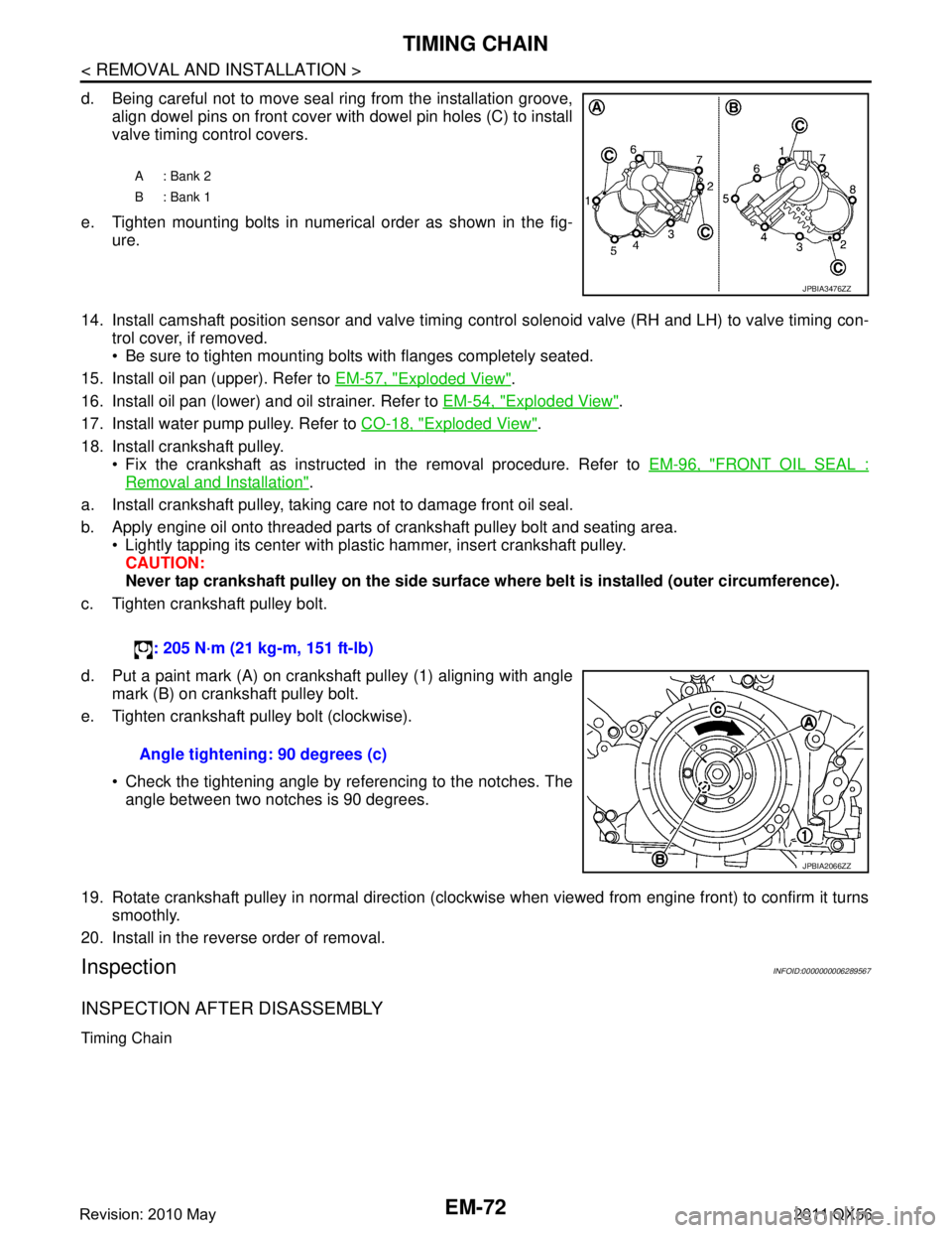
d. Being careful not to move seal ring from the installation groove,align dowel pins on front cover with dowel pin holes (C) to install
valve timing control covers.
e. Tighten mounting bolts in numerical order as shown in the fig- ure.
14. Install camshaft position sensor and valve timing c ontrol solenoid valve (RH and LH) to valve timing con-
trol cover, if removed.
Be sure to tighten mounting bolts with flanges completely seated.
15. Install oil pan (upper). Refer to EM-57, "
Exploded View".
16. Install oil pan (lower) and oil strainer. Refer to EM-54, "
Exploded View".
17. Install water pump pulley. Refer to CO-18, "
Exploded View".
18. Install crankshaft pulley. Fix the crankshaft as instructed in the removal procedure. Refer to EM-96, "
FRONT OIL SEAL :
Removal and Installation".
a. Install crankshaft pulley, taking care not to damage front oil seal.
b. Apply engine oil onto threaded parts of crankshaft pulley bolt and seating area. Lightly tapping its center with plastic hammer, insert crankshaft pulley.
CAUTION:
Never tap crankshaft pulley on the side surface wh ere belt is installed (outer circumference).
c. Tighten crankshaft pulley bolt.
d. Put a paint mark (A) on crankshaft pulley (1) aligning with angle mark (B) on crankshaft pulley bolt.
e. Tighten crankshaft pulley bolt (clockwise).
Check the tightening angle by referencing to the notches. Theangle between two notches is 90 degrees.
19. Rotate crankshaft pulley in normal direction (clockwise when viewed from engine front) to confirm it turns smoothly.
20. Install in the reverse order of removal.
InspectionINFOID:0000000006289567
INSPECTION AFTER DISASSEMBLY
Timing Chain
A: Bank 2
B: Bank 1
JPBIA3476ZZ
: 205 N·m (21 kg-m, 151 ft-lb)
Angle tightening: 90 degrees (c)
JPBIA2066ZZ
Revision: 2010 May2011 QX56
Page 2654 of 5598
![INFINITI QX56 2011 Factory Service Manual
EM-92
< REMOVAL AND INSTALLATION >
CYLINDER HEAD
a. Apply new engine oil on new valve oil seal joint and seal lip.
b. Using the valve oil seal drift [SST: KV10115600 (J-38958)] (A),press fit valve se INFINITI QX56 2011 Factory Service Manual
EM-92
< REMOVAL AND INSTALLATION >
CYLINDER HEAD
a. Apply new engine oil on new valve oil seal joint and seal lip.
b. Using the valve oil seal drift [SST: KV10115600 (J-38958)] (A),press fit valve se](/manual-img/42/57033/w960_57033-2653.png)
EM-92
< REMOVAL AND INSTALLATION >
CYLINDER HEAD
a. Apply new engine oil on new valve oil seal joint and seal lip.
b. Using the valve oil seal drift [SST: KV10115600 (J-38958)] (A),press fit valve seal to height (b) shown in figure.
4. Install valve. NOTE:
Larger diameter valves are for intake side.
5. Install valve spring (with valve spring seat). Install narrow pitch (B) end [paint mark (C)] to cylinder headside (valve spring seat side).
6. Install valve spring retainer.
7. Install valve collet. Compress valve spring with the valve spring compressor [SST:
KV10116200 (J26336-A)] (A), the attachment [SST:
KV10115900 (J26336-20)] (C) and the adapter [SST:
KV10109220 ( — )] (B). Install valve collet with a magnet
hand.
CAUTION:
When working, take care not to damage valve lifter holes.
Tap valve stem edge lightly with plastic hammer after installa- tion to check its installed condition.
InspectionINFOID:0000000006289573
INSPECTION AFTER DISASSEMBLY
Cylinder Head Bolt s Outer Diameter
Cylinder head bolts are tightened by plastic zone tightening
method. Whenever the size difference between (B) and (A)
exceeds the limit, replace them with new one.
If reduction of outer diameter appears in a position other than (A),
use it as (A) point. Height (b)
Intake, Exhaust : 14.3 - 14.9 mm (0.563 - 0.587 in)
JPBIA1367ZZ
A : Wide pitch
: Cylinder head side
Paint mark color
Intake : Light green
Exhaust : Light blue
JPBIA0179ZZ
JPBIA1365ZZ
Limit [(B) - (A)] : 0.18 mm (0.0071 in)
c : 55 mm (2.17 in)
d : 12 mm (0.47 in)
JPBIA2144ZZ
Revision: 2010 May2011 QX56
Page 2673 of 5598

CYLINDER BLOCKEM-111
< UNIT DISASSEMBLY AND ASSEMBLY >
C
DE
F
G H
I
J
K L
M A
EM
NP
O
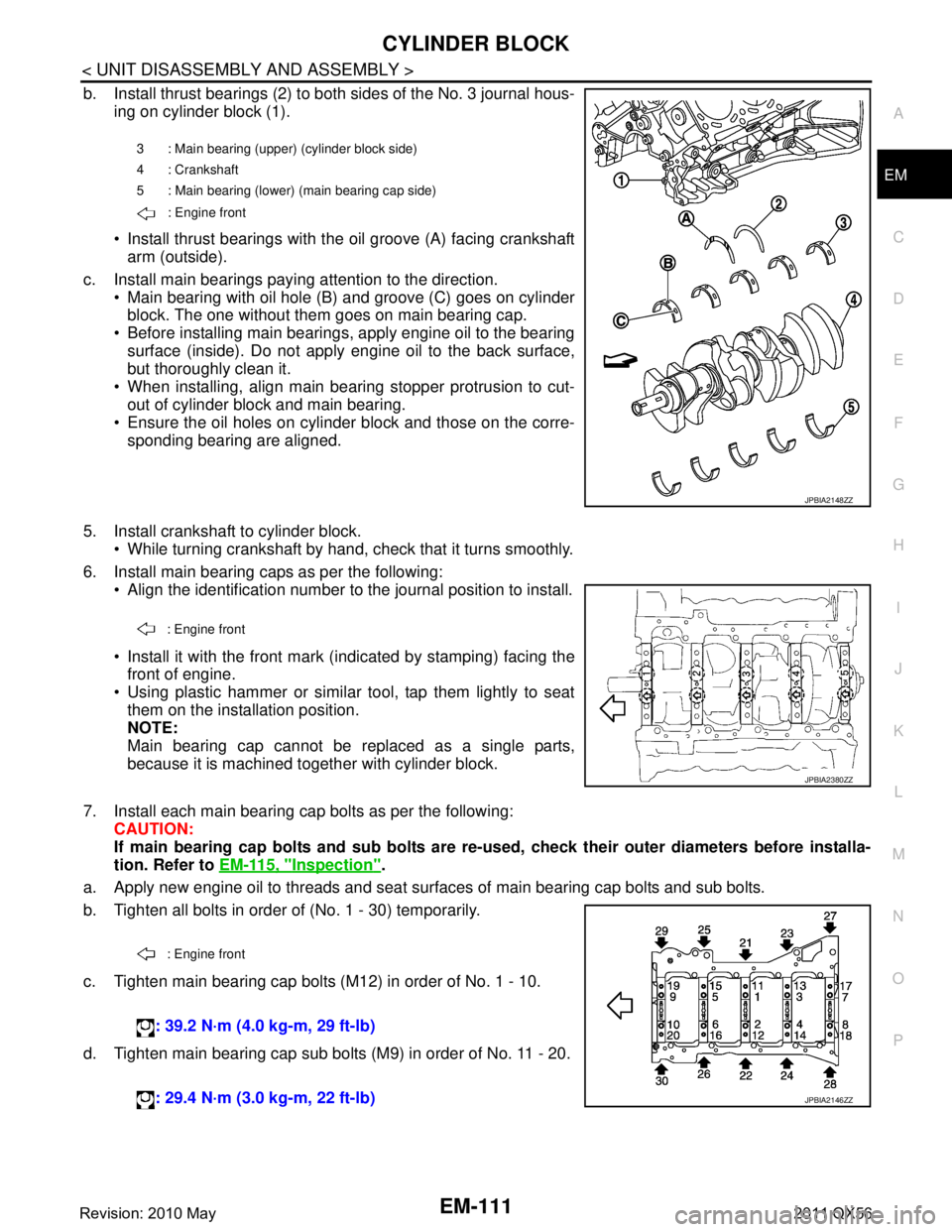
b. Install thrust bearings (2) to both sides of the No. 3 journal hous-
ing on cylinder block (1).
Install thrust bearings with the oil groove (A) facing crankshaftarm (outside).
c. Install main bearings paying attention to the direction. Main bearing with oil hole (B) and groove (C) goes on cylinderblock. The one without them goes on main bearing cap.
Before installing main bearings, apply engine oil to the bearing surface (inside). Do not apply engine oil to the back surface,
but thoroughly clean it.
When installing, align main bearing stopper protrusion to cut-
out of cylinder block and main bearing.
Ensure the oil holes on cylinder block and those on the corre-
sponding bearing are aligned.
5. Install crankshaft to cylinder block. While turning crankshaft by hand, check that it turns smoothly.
6. Install main bearing caps as per the following: Align the identification number to the journal position to install.
Install it with the front mark (indicated by stamping) facing thefront of engine.
Using plastic hammer or similar tool, tap them lightly to seat them on the installation position.
NOTE:
Main bearing cap cannot be replaced as a single parts,
because it is machined together with cylinder block.
7. Install each main bearing cap bolts as per the following: CAUTION:
If main bearing cap bolts and sub bolts are re-u sed, check their outer diameters before installa-
tion. Refer to EM-115, "
Inspection".
a. Apply new engine oil to threads and seat surfaces of main bearing cap bolts and sub bolts.
b. Tighten all bolts in order of (No. 1 - 30) temporarily.
c. Tighten main bearing cap bolts (M12) in order of No. 1 - 10.
d. Tighten main bearing cap sub bolts (M9) in order of No. 11 - 20.
3 : Main bearing (uppe r) (cylinder block side)
4 : Crankshaft
5 : Main bearing (lower) (main bearing cap side)
: Engine front
JPBIA2148ZZ
: Engine front
JPBIA2380ZZ
: Engine front
: 39.2 N·m (4.0 kg-m, 29 ft-lb)
: 29.4 N·m (3.0 kg-m, 22 ft-lb)
JPBIA2146ZZ
Revision: 2010 May2011 QX56
Page 2726 of 5598
![INFINITI QX56 2011 Factory Service Manual
EXL-16
< SYSTEM DESCRIPTION >[XENON TYPE]
SYSTEM
- Swivels the headlamp to the vehicle-center side until it hits the stopper.
- Returns the swivel angle from the stopper. Completes t
he initializatio INFINITI QX56 2011 Factory Service Manual
EXL-16
< SYSTEM DESCRIPTION >[XENON TYPE]
SYSTEM
- Swivels the headlamp to the vehicle-center side until it hits the stopper.
- Returns the swivel angle from the stopper. Completes t
he initializatio](/manual-img/42/57033/w960_57033-2725.png)
EXL-16
< SYSTEM DESCRIPTION >[XENON TYPE]
SYSTEM
- Swivels the headlamp to the vehicle-center side until it hits the stopper.
- Returns the swivel angle from the stopper. Completes t
he initialization with regarding the returned position
as the swivel angle 0 ° (straight-forward position).
Swivel Operation
AFS control unit transmits the drive signal to the sw ivel actuator when activation conditions are satisfied.
And swivels the headlamp.
- The swivel starts after steering approximately 20 ° or more from straight-forward position.
NOTE:
The steering angle differs between right turn and left turn.
- The swivel angle becomes the maximum angle toward t he driving direction if the steering angle is approxi-
mately 90 ° or more depending on the vehicle speed. The swivel angle is maintained by shutting off the drive
signal.
- The swivel starts, and returns to the swivel angle 0 ° (straight-forward position) when the steering is returned
to the straight-forward position.
AFS control unit returns the swivel angle to the strai ght-forward position, and stops the swivel regardless of
the steering angle if the operation condition is not satisfied while the swivel angle is 0°.
AFS OFF Indicator Lamp
AFS control unit transmits AFS OFF indicator lamp signal to the combination meter via CAN communication.
Combination meter turns AFS OFF indicator lamp ON /OFF/blinking according to AFS OFF indicator lamp
signal.
- AFS OFF indicator lamp is turned ON for 1 second for the AFS OFF indicator lamp bulb check when the igni-
tion switch is turned ON. AFS OFF indicator lamp is turned OFF within 1 second when the engine starts.
- AFS OFF indicator lamp turns ON when AFS is switched to “OFF” by operating AFS switch.
- AFS OFF indicator lamp blinks (1 second each) if AFS control unit detects a specific DTC.
NOTE:
Combination meter blinks AFS OFF indicator lamp (approximately 1 second each) if AFS OFF indicator
lamp signal is not received from AFS control unit.
HEADLAMP AUTO AIMING
Headlamp Auto Aiming Control Description
AFS control unit controls the headl amp light axis height appropriately according to the vehicle height.
AFS control unit detects the vehicle condition necessa ry for headlamp auto aiming control with the following
signals.
- Height sensor signals (front and rear)
- Vehicle speed signal (received from combination meter via CAN communication)
- Low beam status signal (received from IPDM E/R via CAN communication)
- Engine speed signal (received from ECM via CAN communication)
When the operation conditions are satisfied, AFS cont rol unit transmits the aiming motor drive signal for
adjusting the headlamp axis height.
Headlamp auto aiming operation condition- Headlamp ON
- While the engine running
- Vehicle speed (Control mode is switched according to the driving condition.)
Headlamp Auto Aiming Operation
AFS control unit calculates the vehicle pitch angle fr om the front and rear height sensor signal. AFS control
unit judges the angle for adjusting the axis gap from the preset position.
AFS control unit controls the headlamp axis by c hanging the aiming motor drive signal output according to
the front and rear vehicle height when detecting the follo wing vehicle condition. Output is maintained if other
condition than following is detected.
- Engine starts.
- Headlamp is turned ON.
- Vehicle posture becomes stable after changing the v ehicle posture change is detected with the headlamp
ON and the vehicle stopped.
- Vehicle speed is maintained with the headlamp ON and the vehicle driven.
CAUTION:
Adjusted axis position may differ from the preset position although the headlamp auto aiming acti-
vates properly if the suspension is replaced or worn.
Revision: 2010 May2011 QX56
Page 2771 of 5598
![INFINITI QX56 2011 Factory Service Manual
INSPECTION AND ADJUSTMENTEXL-61
< BASIC INSPECTION > [XENON TYPE]
C
D
E
F
G H
I
J
K
M A
B
EXL
N
O P
INSPECTION AND ADJUSTMENT
ADDITIONAL SERVICE WHEN REPLAC ING CONTROL UNIT (AFS CONTROL
UNIT)
ADDITI INFINITI QX56 2011 Factory Service Manual
INSPECTION AND ADJUSTMENTEXL-61
< BASIC INSPECTION > [XENON TYPE]
C
D
E
F
G H
I
J
K
M A
B
EXL
N
O P
INSPECTION AND ADJUSTMENT
ADDITIONAL SERVICE WHEN REPLAC ING CONTROL UNIT (AFS CONTROL
UNIT)
ADDITI](/manual-img/42/57033/w960_57033-2770.png)
INSPECTION AND ADJUSTMENTEXL-61
< BASIC INSPECTION > [XENON TYPE]
C
D
E
F
G H
I
J
K
M A
B
EXL
N
O P
INSPECTION AND ADJUSTMENT
ADDITIONAL SERVICE WHEN REPLAC ING CONTROL UNIT (AFS CONTROL
UNIT)
ADDITIONAL SERVICE WHEN REPLAC ING CONTROL UNIT (AFS CONTROL
UNIT) : Description
INFOID:0000000006213923
Perform “LEVELIZER ADJUSTMENT” with CONSUL T-III when replacing the AFS control unit.
ADDITIONAL SERVICE WHEN REPLACING CONTROL UNIT (AFS CONTROL
UNIT) : Special Repair Requirement
INFOID:0000000006213924
1.LEVELIZER ADJUSTMENT
Perform “LEVELIZER ADJUSTMENT”.
>> Refer to EXL-61, "
LEVELIZER ADJUSTMENT : Special Repair Requirement".
ADDITIONAL SERVICE WHEN REPLACING CONTROL UNIT (HEIGHT SEN-
SOR)
ADDITIONAL SERVICE WHEN REPLACING CONTROL UNIT (HEIGHT SENSOR) :
Description
INFOID:0000000006213925
Perform “LEVELIZER ADJUSTMENT” with CONS ULT-III when replacing the height sensor.
ADDITIONAL SERVICE WHEN REPLACING CONTROL UNIT (HEIGHT SENSOR) :
Special Repair Requirement
INFOID:0000000006213926
1.LEVELIZER ADJUSTMENT
Perform “LEVELIZER ADJUSTMENT”.
>> Refer to EXL-61, "
LEVELIZER ADJUSTMENT : Special Repair Requirement".
LEVELIZER ADJUSTMENT
LEVELIZER ADJUSTMENT : DescriptionINFOID:0000000006213927
Perform “LEVELIZER ADJUSTME NT” when installing, removing, and replacing the height sensor and the sus-
pension components.
LEVELIZER ADJUSTMENT : S pecial Repair RequirementINFOID:0000000006213928
CAUTION:
If perform aiming adjustment after the levelizer initia lization, be sure to start the engine running after
turning ignition switch OFF.
1.CHECK VEHICLE CONDITION
1. Park the vehicle in the straight-forward position.
2. Unload the vehicle (no passenger aboard).
>> GO TO 2.
2.LEVELIZER ADJUSTMENT
CONSULT-III WORK SUPPORT
1. Select “LEVELIZER ADJUSTMENT” of ADAPTIVE LIGHT work support item.
2. Select “START”.
3. When “ADJUSTMENT IS CO MPLETED”, select “END”.
CAUTION:
Revision: 2010 May2011 QX56