2011 INFINITI QX56 fuel cap
[x] Cancel search: fuel capPage 2552 of 5598
![INFINITI QX56 2011 Factory Service Manual
E C -528
< SYMPTOM DIAGNOSIS >[VK56VD]
ENGINE CONTROL SYSTEM SYMPTOMS
1 - 6: The numbers refer to the order of inspection.Lubrica-
tion
Oil pan/Oil strainer/Oil pump/Oil
filter/Oil gallery/Oil coole INFINITI QX56 2011 Factory Service Manual
E C -528
< SYMPTOM DIAGNOSIS >[VK56VD]
ENGINE CONTROL SYSTEM SYMPTOMS
1 - 6: The numbers refer to the order of inspection.Lubrica-
tion
Oil pan/Oil strainer/Oil pump/Oil
filter/Oil gallery/Oil coole](/manual-img/42/57033/w960_57033-2551.png)
E C -528
< SYMPTOM DIAGNOSIS >[VK56VD]
ENGINE CONTROL SYSTEM SYMPTOMS
1 - 6: The numbers refer to the order of inspection.Lubrica-
tion
Oil pan/Oil strainer/Oil pump/Oil
filter/Oil gallery/Oil cooler 55555 55 5 EM-56
EM-60
LU-9
LU-12
LU-14
Oil level (Low)/Filthy oil
LU-7
Cooling
Radiator/Hose/Radiator filler cap
55555 55 45 CO-11
CO-11
Thermostat 5
CO-21
Water pumpCO-19
Water galleryEM-115
Cooling fan
5CO-17
Coolant level (Low)/Contaminat-
ed coolant
CO-8
IVIS (INFINITI Vehicle Immobilizer System —
NATS)11
SEC-48
SYMPTOM
Reference
page
HARD/NO START/RESTART (EXCP. HA)
ENGINE STALL
HESITATION/SURGING/FLAT SPOT
SPARK KNOCK/DETONATION
LACK OF POWER/POOR ACCELERATION
HIGH IDLE/LOW IDLE
ROUGH IDLE/HUNTING
IDLING VIBRATION
SLOW/NO RETURN TO IDLE
OVERHEATS/WATER TEMPERATURE HIGH
EXCESSIVE FUEL CONSUMPTION
EXCESSIVE OIL CONSUMPTION
BATTERY DEAD (UNDER CHARGE)
Warranty symptom code AA AB AC AD AE AF AG AH AJ AK AL AM HA
Revision: 2010 May2011 QX56
Page 2567 of 5598
PRECAUTIONSEM-5
< PRECAUTION >
C
DE
F
G H
I
J
K L
M A
EM
NP
O
Avoid damaging sliding or mating surfaces. Completely re
move foreign materials such as cloth lint or dust.
Before assembly, oil sliding surfaces well.
Release air within route when refilling after draining engine coolant.
After repairing, start engine and increase engine speed to check engine coolant, fuel, engine oil, and
exhaust gases for leakage.
Parts Requiring Angle TighteningINFOID:0000000006289515
Use angle wrench [SST: KV10112100 (BT8653-A)] for the final tightening of the following engine parts:
- Cylinder head bolts
- Main bearing cap bolts
- Main bearing cap sub bolts
- Connecting rod cap bolts
- Crankshaft pulley bolt (No angle wrench is required as the bolt flange is provided with notches for angletightening)
Ensure thread and seat surfaces are clean and coated with engine oil.
Precaution for Liquid GasketINFOID:0000000006289516
REMOVAL OF LIQUID GASKET SEALING
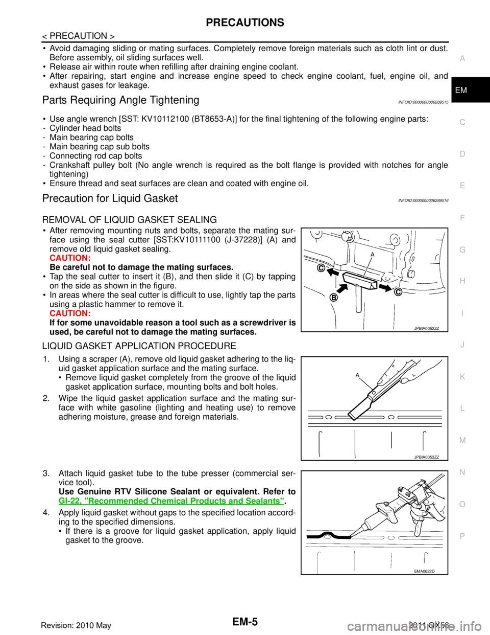
After removing mounting nuts and bolts, separate the mating sur- face using the seal cutter [SST:KV10111100 (J-37228)] (A) and
remove old liquid gasket sealing.
CAUTION:
Be careful not to damage the mating surfaces.
Tap the seal cutter to insert it (B), and then slide it (C) by tapping on the side as shown in the figure.
In areas where the seal cutter is difficult to use, lightly tap the parts using a plastic hammer to remove it.
CAUTION:
If for some unavoidable reason a tool such as a screwdriver is
used, be careful not to damage the mating surfaces.
LIQUID GASKET APPLICATION PROCEDURE
1. Using a scraper (A), remove old liquid gasket adhering to the liq- uid gasket application surface and the mating surface.
Remove liquid gasket completely from the groove of the liquidgasket application surface, mounting bolts and bolt holes.
2. Wipe the liquid gasket application surface and the mating sur- face with white gasoline (lighting and heating use) to remove
adhering moisture, grease and foreign materials.
3. Attach liquid gasket tube to the tube presser (commercial ser- vice tool).
Use Genuine RTV Silicone Seal ant or equivalent. Refer to
GI-22, "
Recommended Chemical Products and Sealants".
4. Apply liquid gasket without gaps to the specified location accord- ing to the specified dimensions.
If there is a groove for liquid gasket application, apply liquidgasket to the groove.
JPBIA0052ZZ
JPBIA0053ZZ
EMA0622D
Revision: 2010 May2011 QX56
Page 2595 of 5598
ROCKER COVEREM-33
< REMOVAL AND INSTALLATION >
C
DE
F
G H
I
J
K L
M A
EM
NP
O
ROCKER COVER
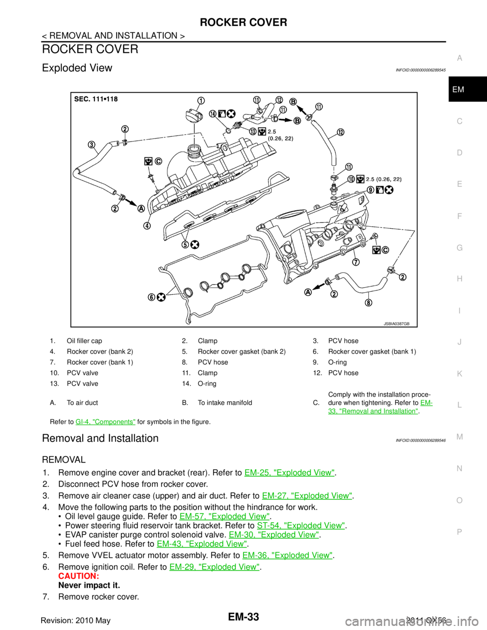
Exploded ViewINFOID:0000000006289545
Removal and InstallationINFOID:0000000006289546
REMOVAL
1. Remove engine cover and bracket (rear). Refer to
EM-25, "Exploded View".
2. Disconnect PCV hose from rocker cover.
3. Remove air cleaner case (upper) and air duct. Refer to EM-27, "
Exploded View".
4. Move the following parts to the position without the hindrance for work. Oil level gauge guide. Refer to EM-57, "
Exploded View".
Power steering fluid reservoir tank bracket. Refer to ST-54, "
Exploded View".
EVAP canister purge control solenoid valve. EM-30, "
Exploded View".
Fuel feed hose. Refer to EM-43, "
Exploded View".
5. Remove VVEL actuator motor assembly. Refer to EM-36, "
Exploded View".
6. Remove ignition coil. Refer to EM-29, "
Exploded View".
CAUTION:
Never impact it.
7. Remove rocker cover.
1. Oil filler cap 2. Clamp 3. PCV hose
4. Rocker cover (bank 2) 5. Rocker cover gasket (bank 2) 6. Rocker cover gasket (bank 1)
7. Rocker cover (bank 1) 8. PCV hose 9. O-ring
10. PCV valve 11. Clamp 12. PCV hose
13. PCV valve 14. O-ring
A. To air duct B. To intake manifold C. Comply with the installation proce-
dure when tightening. Refer to
EM-
33, "Removal and Installation".
Refer to GI-4, "
Components" for symbols in the figure.
JSBIA0387GB
Revision: 2010 May2011 QX56
Page 2606 of 5598
EM-44
< REMOVAL AND INSTALLATION >
HIGH PRESSURE FUEL PUMP AND FUEL HOSE
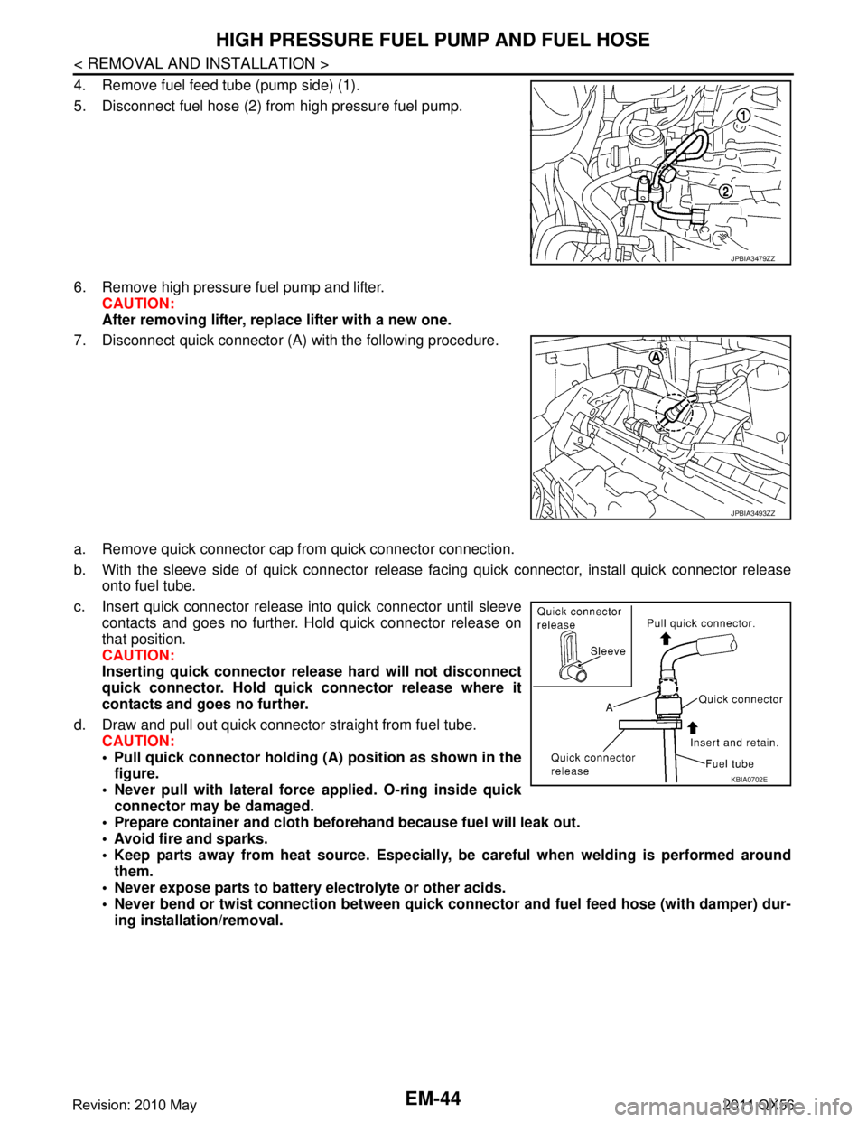
4. Remove fuel feed tube (pump side) (1).
5. Disconnect fuel hose (2) from high pressure fuel pump.
6. Remove high pressure fuel pump and lifter.CAUTION:
After removing lifter, replace lifter with a new one.
7. Disconnect quick connector (A) with the following procedure.
a. Remove quick connector cap from quick connector connection.
b. With the sleeve side of quick connector release facing quick connector, install quick connector release
onto fuel tube.
c. Insert quick connector release into quick connector until sleeve contacts and goes no further. Hold quick connector release on
that position.
CAUTION:
Inserting quick connector re lease hard will not disconnect
quick connector. Hold qui ck connector release where it
contacts and goes no further.
d. Draw and pull out quick connector straight from fuel tube. CAUTION:
Pull quick connector holding (A) position as shown in thefigure.
Never pull with lateral force applied. O-ring inside quick
connector may be damaged.
Prepare container and cloth befo rehand because fuel will leak out.
Avoid fire and sparks.
Keep parts away from heat source. Especially, be careful when welding is performed around
them.
Never expose parts to battery electrolyte or other acids.
Never bend or twist connection between quick c onnector and fuel feed hose (with damper) dur-
ing installation/removal.
JPBIA3479ZZ
JPBIA3493ZZ
KBIA0702E
Revision: 2010 May2011 QX56
Page 2608 of 5598
EM-46
< REMOVAL AND INSTALLATION >
HIGH PRESSURE FUEL PUMP AND FUEL HOSE
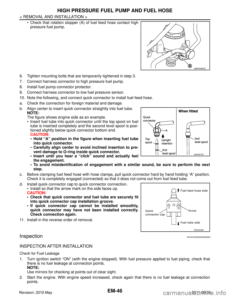
Check that rotation stopper (A) of fuel feed hose contact highpressure fuel pump.
6. Tighten mounting bolts that are temporarily tightened in step 3.
7. Connect harness connector to high pressure fuel pump.
8. Install fuel pump connector protector.
9. Connect harness connector to low fuel pressure sensor.
10. Note the following, and connect quick connector to install fuel feed hose.
a. Check the connection for foreign material and damage.
b. Align center to insert quick connector straightly into fuel tube. NOTE:
The figure shows engine side as an example.
Insert fuel tube into quick connector until the top spool on fueltube is inserted completely and the second level spool is posi-
tioned slightly below quick connector bottom end.
CAUTION:
Hold “A” position in the figure when inserting fuel tube
into quick connector.
Carefully align center to avoid inclined insertion to pre-
vent damage to O-ring inside quick connector.
Insert until you hear a “c lick” sound and actually feel
the engagement.
To avoid misidentification of engagement with a similar sound , be sure to perform the next
step.
c. Before clamping fuel feed hose with hose clamps, pull quick connector hard by hand holding “A” position.
Check it is completely engaged (connected) so that it does not come out from fuel feed tube.
d. Install quick connector cap to quick connector connection. Install so that the arrow mark on the side faces up.
CAUTION:
Check that quick connector and fuel tube are securely fitinto quick connector cap installation groove.
If quick connector cap canno t be installed smoothly,
quick connector may have not been installed correctly.
Check connection again.
11. Install in the reverse order of removal.
InspectionINFOID:0000000006289555
INSPECTION AFTER INSTALLATION
Check for Fuel Leakage
1. Turn ignition switch “ON” (with the engine stopped). With fuel pressure applied to fuel piping, check that
there is no fuel leakage at connection points.
NOTE:
Use mirrors for checking at points out of clear sight.
2. Start the engine. With engine speed increased, check again that there is no fuel leakage at connection
points.
JSBIA0364ZZ
KBIA0272E
PBIC2348E
Revision: 2010 May2011 QX56
Page 2665 of 5598

ENGINE STAND SETTINGEM-103
< UNIT DISASSEMBLY AND ASSEMBLY >
C
DE
F
G H
I
J
K L
M A
EM
NP
O
UNIT DISASSEMBLY AND ASSEMBLY
ENGINE STAND SETTING
SettingINFOID:0000000006289579
NOTE:
Explained here is how to disassemble with engine stand s
upporting transmission surface. When using a differ-
ent type of engine stand, note the difference in the steps, etc.
1. Remove the engine assembly from the vehicle. Refer to EM-98, "
Exploded View".
2. Remove crankshaft pulley. Refer to EM-96, "
FRONT OIL SEAL : Removal and Installation".
NOTE:
The drive plate is fixed with a ring gear stopper [SST: KV10119200 (J-49277)]. Loosen the crankshaft pul-
ley mounting bolts before installing the engine stand.
3. Remove the parts that may restrict installation of engine to a widely used engine stand. Fix crankshaft with a ring gear stopper [SST: KV10119200 (J-49277)]. Loosen drive plate mounting bolt
with power tool.
Check for deformation or damage of drive plate. Refer to EM-115, "
Inspection".
NOTE:
The procedure is described assuming that you us e a widely used engine stand holding the surface, to
which transmission is installed.
4. Remove pilot converter using the pilot bushing puller (commercial service tool), if necessary.
5. Lift the engine with hoist to inst all it onto the widely used engine stand.
CAUTION:
Use an engine stand that has a load capacity [240 kg (529 lb) or more] large enough for supporting
the engine weight.
If the load capacity of the stand is not adequate, remove the following parts beforehand to reduce the potential risk of overturning the stand.
- Remove intake manifold. Refer to EM-30, "
Exploded View".
- Remove fuel injector and fuel tube assembly. Refer to EM-48, "
Exploded View".
- Remove ignition coil. Refer to EM-29, "
Exploded View".
- Remove rocker cover. Refer to EM-33, "
Exploded View".
- Remove exhaust manifold. Refer to EM-40, "
Exploded View".
- Other removable brackets. NOTE:
The figure shows an example of widely used engine stand (A)
that can hold mating surface of transmission with drive plate
removed.
CAUTION:
Before removing the hang ing chains, check the engine
stand is stable and there is no risk of overturning.
6. Drain engine oil. Refer to LU-8, "
Draining".
JPBIA0190ZZ
Revision: 2010 May2011 QX56
Page 2931 of 5598
FL-2
< PRECAUTION >
PRECAUTIONS
PRECAUTION
PRECAUTIONS
General PrecautionsINFOID:0000000006289679
WARNING:
When replacing fuel line parts, be sure to observe the following.
• Put a “CAUTION: FLAMMABLE” sign in the workshop.
Be sure to work in a well ventilate d area and furnish workshop with a CO
2 fire extinguisher.
Never smoke while servicing fuel system. Keep open flames and sparks away from the work area.
CAUTION:
Use gasoline required by the regulations for octane number. Refer to GI-31, "
Fuel".
Before removing fuel line parts, perform out the following procedures:
- Put drained fuel in an explosi on-proof container and put the lid on securely. Keep the container in
safe area.
- Release fuel pressure from the fuel lines. Refer to EC-153, "
Work Procedure".
- Disconnect the battery cable from the negative terminal.
Always replace O-rings with new ones.
Never kink or twist tubes when they are being installed.
Never tighten hose clamps excessi vely to avoid damaging hoses.
After installing tubes, check there is no fuel leakage at connections in the following steps.
- Apply fuel pressure to fuel lin es with turning ignition switch “O N” (with engine stopped). Then check
for fuel leakage at connections.
- Start engine and rev it up and check for fuel leakage at connections.
Use only a genuine NISSAN fuel filler cap as a replacemen t. If an incorrect fuel filler cap is used, the
“MIL” may come on.
For servicing “Evaporative Emission System” parts.
Refer to EC-16, "
Component Parts Location".
Revision: 2010 May2011 QX56
Page 2933 of 5598
FL-4
< PERIODIC MAINTENANCE >
FUEL SYSTEM
PERIODIC MAINTENANCE
FUEL SYSTEM
InspectionINFOID:0000000006289682
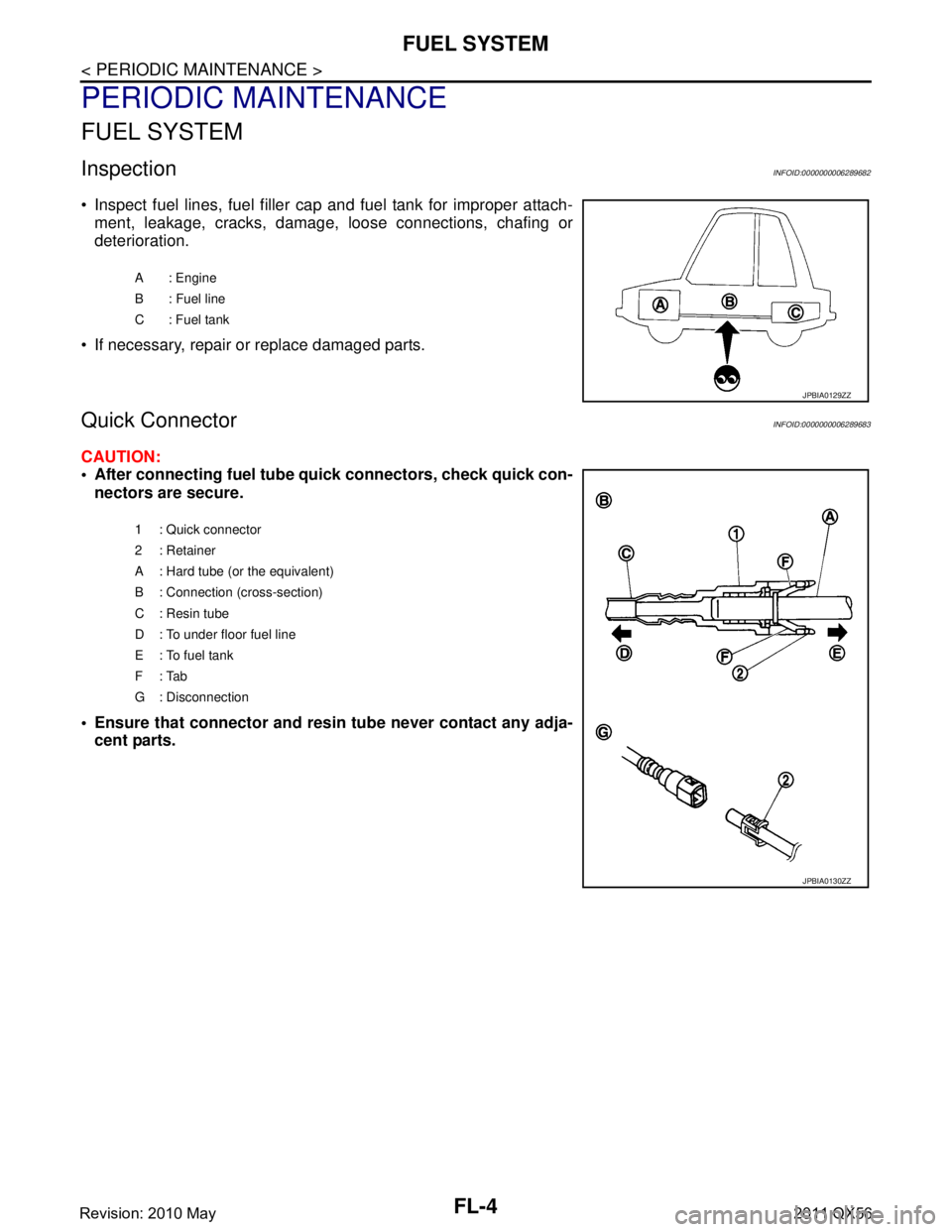
• Inspect fuel lines, fuel filler cap and fuel tank for improper attach-ment, leakage, cracks, damage, loose connections, chafing or
deterioration.
If necessary, repair or replace damaged parts.
Quick ConnectorINFOID:0000000006289683
CAUTION:
After connecting fuel tube quick connectors, check quick con-
nectors are secure.
Ensure that connector and resi n tube never contact any adja-
cent parts.
A : Engine
B : Fuel line
C: Fuel tank
JPBIA0129ZZ
1 : Quick connector
2: Retainer
A : Hard tube (or the equivalent)
B : Connection (cross-section)
C : Resin tube
D : To under floor fuel line
E : To fuel tank
F: Tab
G : Disconnection
JPBIA0130ZZ
Revision: 2010 May2011 QX56