Page 3687 of 5598

ENGINE MAINTENANCEMA-17
< PERIODIC MAINTENANCE >
C
DE
F
G H
I
J
K L
M B
MA
N
O A
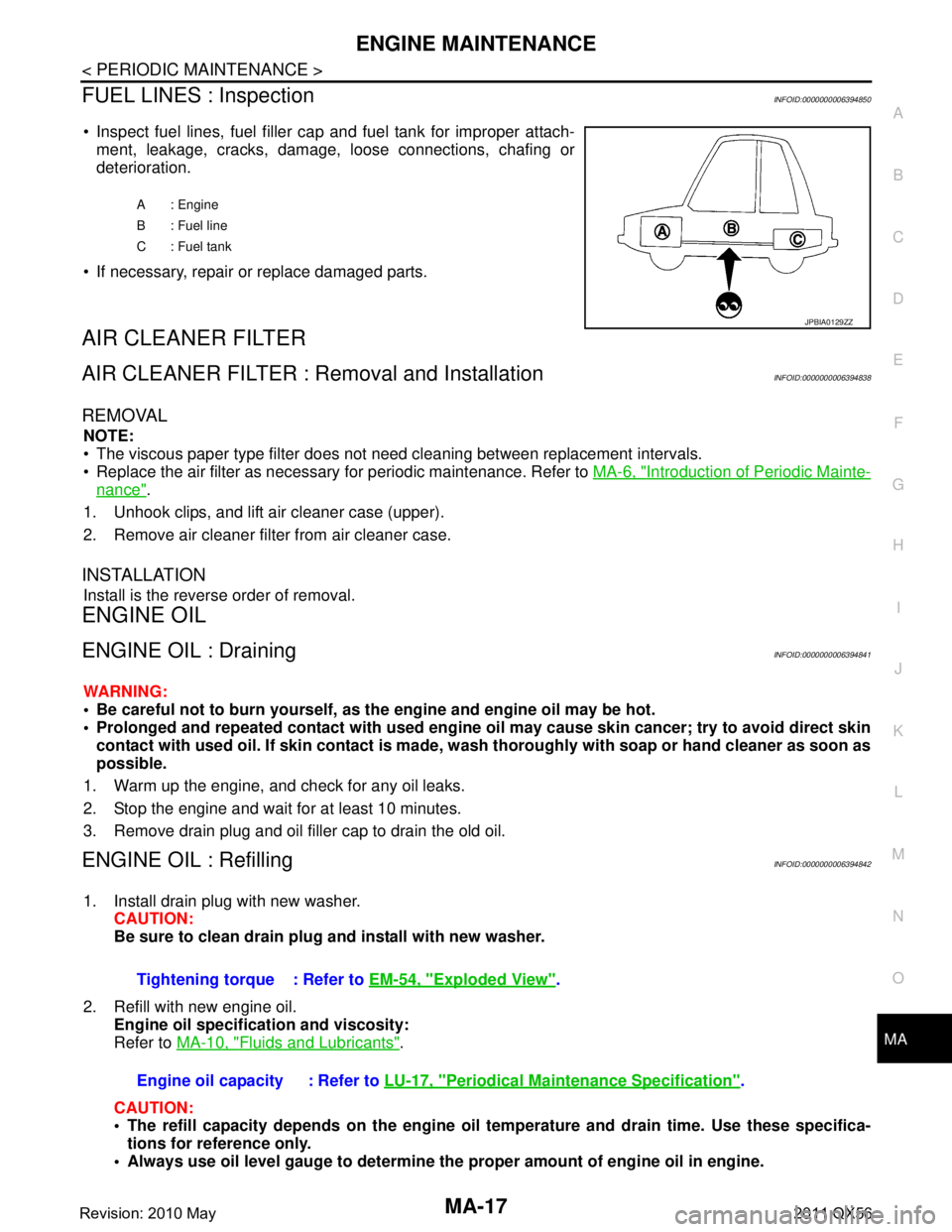
FUEL LINES : InspectionINFOID:0000000006394850
Inspect fuel lines, fuel filler cap and fuel tank for improper attach-
ment, leakage, cracks, damage, loose connections, chafing or
deterioration.
If necessary, repair or replace damaged parts.
AIR CLEANER FILTER
AIR CLEANER FILTER : Removal and InstallationINFOID:0000000006394838
REMOVAL
NOTE:
The viscous paper type filter does not need cleaning between replacement intervals.
Replace the air filter as necessary for periodic maintenance. Refer to MA-6, "
Introduction of Periodic Mainte-
nance".
1. Unhook clips, and lift air cleaner case (upper).
2. Remove air cleaner filter from air cleaner case.
INSTALLATION
Install is the reverse order of removal.
ENGINE OIL
ENGINE OIL : DrainingINFOID:0000000006394841
WARNING:
Be careful not to burn yourself, as th e engine and engine oil may be hot.
Prolonged and repeated contact with used engine oil may cau se skin cancer; try to avoid direct skin
contact with used oil. If skin contact is made, w ash thoroughly with soap or hand cleaner as soon as
possible.
1. Warm up the engine, and check for any oil leaks.
2. Stop the engine and wait for at least 10 minutes.
3. Remove drain plug and oil filler cap to drain the old oil.
ENGINE OIL : RefillingINFOID:0000000006394842
1. Install drain plug with new washer. CAUTION:
Be sure to clean drain plug and install with new washer.
2. Refill with new engine oil. Engine oil specificat ion and viscosity:
Refer to MA-10, "
Fluids and Lubricants".
CAUTION:
The refill capacity depends on the engine oi l temperature and drain time. Use these specifica-
tions for reference only.
Always use oil level gauge to determine the proper amount of engine oil in engine.
A : Engine
B : Fuel line
C : Fuel tank
JPBIA0129ZZ
Tightening torque : Refer to EM-54, "Exploded View".
Engine oil capacity : Refer to LU-17, "
Periodical Maintenance Specification".
Revision: 2010 May2011 QX56
Page 3690 of 5598
MA-20
< PERIODIC MAINTENANCE >
ENGINE MAINTENANCE
Spark plug gap adjustment is not required between replace-ment intervals.
EVAP VAPOR LINES
EVAP VAPOR LINES : InspectionINFOID:0000000006220923
1. Visually inspect EVAP vapor lines for improper attachment and for cracks, damage, loose connections,
chafing and deterioration.
2. Inspect fuel tank filler cap vacuum relief valve for clogging, sticking, etc.
Refer to EC-532, "
Inspection".
JPBIA0031ZZ
Revision: 2010 May2011 QX56
Page 4261 of 5598

RSU-6
< PERIODIC MAINTENANCE >
WHEEL ALIGNMENT
WHEEL ALIGNMENT
InspectionINFOID:0000000006225661
DESCRIPTION
Measure wheel alignment under unladen conditions.
NOTE:
“Unladen conditions” means that fuel, engine coolant, and lubricant are full. Spare tire, jack, hand tools and
mats are in designated positions.
PRELIMINARY CHECK
Check the following:
Tires for improper air pressure and wear
Road wheels for runout. Refer to WT-64, "
Inspection".
Wheel bearing axial end play. Refer to RAX-5, "
Inspection".
Ball joint axial end play of suspension arm and front lower link. Refer to RSU-20, "
Ball Joint".
Shock absorber operation
Each mounting point of axle and suspension for looseness and deformation
Each of front lower link, rear lower link, rear suspension member, suspension arm and shock absorber for
cracks, deformation, and other damage
Vehicle height (posture)
GENERAL INFORMATION AND RECOMMENDATIONS
A four-wheel thrust alignment should be performed.
- This type of alignment is recomm ended for any NISSAN/INFINITI vehicle.
- The four-wheel “thrust” process helps ensure that t he vehicle is properly aligned and the steering wheel is
centered.
- The alignment rack itself should be capable of accepting any NISSAN/INFINITI vehicle.
- The rack should be checked to ensure that it is level.
Make sure the machine is properly calibrated.
- Your alignment equipment should be regularly calib rated in order to give correct information.
- Check with the manufacturer of your specific equi pment for their recommended Service/Calibration Sched-
ule.
ALIGNMENT PROCESS
IMPORTANT:
Use only the alignment specifications listed in this Service Manual.
When displaying the alignment settings, many alignment machines use “indicators”: (Green/red, plus or
minus, Go/No Go). Never use these indicators.
- The alignment specifications programmed into your machine that operate these indicators may not be cor-
rect.
- This may result in an ERROR.
Some newer alignment machines are equipped with an optional “Rolling Compensation” method to “com- pensate” the sensors (alignment targets or head units). Never use this “Rolling Compensation” method.
- Use the “Jacking Compensation Method”. After installi ng the alignment targets or head units, raise the vehi-
cle and rotate the wheels 1/2 turn both ways.
- See Instructions in the alignment machine you're using for more information on this.
AdjustmentINFOID:0000000006225662
CAMBER
Revision: 2010 May2011 QX56