2011 INFINITI QX56 battery location
[x] Cancel search: battery locationPage 2468 of 5598
![INFINITI QX56 2011 Factory Service Manual
EC-444
< DTC/CIRCUIT DIAGNOSIS >[VK56VD]
P1572 ICC BRAKE SWITCH
Always drive vehicle at a safe speed.
NOTE:
This procedure may be conducted with the drive wheel
s lifted in the shop or by driving the INFINITI QX56 2011 Factory Service Manual
EC-444
< DTC/CIRCUIT DIAGNOSIS >[VK56VD]
P1572 ICC BRAKE SWITCH
Always drive vehicle at a safe speed.
NOTE:
This procedure may be conducted with the drive wheel
s lifted in the shop or by driving the](/manual-img/42/57033/w960_57033-2467.png)
EC-444
< DTC/CIRCUIT DIAGNOSIS >[VK56VD]
P1572 ICC BRAKE SWITCH
Always drive vehicle at a safe speed.
NOTE:
This procedure may be conducted with the drive wheel
s lifted in the shop or by driving the vehicle.
If a road test is expected to be easier , it is unnecessary to lift the vehicle.
2. Check 1st trip DTC.
Is 1st trip DTC detected?
YES >> Go to EC-444, "Diagnosis Procedure".
NO >> INSPECTION END
Diagnosis ProcedureINFOID:0000000006217948
1.CHECK DTC WITH ADAS CONTROL UNIT
Refer to DAS-21, "
CONSULT-III Function (ICC/ADAS)" and DAS-38, "DTC Index".
Are any DTCs detected?
YES >> Perform the Diagnosis Procedure corresponding to the detected DTC.
NO >> GO TO 2.
2.CHECK OVERALL FUNCTION-I
WITH CONSULT-III
1. Turn ignition switch ON.
2. Select “BRAKE SW1” in “DAT A MONITOR” mode with CONSULT-III.
3. Check “BRAKE SW1” indication under the following conditions.
WITHOUT CONSULT-III
1. Turn ignition switch ON.
2. Check the voltage between ECM harness connector terminals under the following conditions.
Is the inspection result normal?
YES >> GO TO 8.
NO >> GO TO 3.
3.CHECK ICC BRAKE SWITCH POWER SUPPLY CIRCUIT-I
1. Turn ignition switch OFF.
2. Disconnect ICC brake switch harness connector.
3. Turn ignition switch ON.
4. Check the voltage between ICC brake switch harness connector and ground.
Vehicle speed More than 30 km/h (19 mph)
Selector lever Suitable position
Driving location Depress the brake pedal for more than 5 seconds so as
not to come off from the above-mentioned vehicle speed.
Monitor item Condition Indication
BRAKE SW1
(ICC brake switch) Brake pedalSlightly depressed OFF
Fully released ON
ECM Condition Voltage (V)
Connector +–
Te r m i n a l Te r m i n a l
E80 147
(ICC brake switch signal) 175 Brake pedalSlightly depressed Approx. 0
Fully released Battery voltage
ICC brake switch
Ground Voltage
Connector Terminal
E68 1 Ground Battery voltage
Revision: 2010 May2011 QX56
Page 2711 of 5598

EXL-1
DRIVER CONTROLS
C
DE
F
G H
I
J
K
M
SECTION EXL
A
B
EXL
N
O P
CONTENTS
EXTERIOR LIGHTING SYSTEM
XENON TYPE
PRECAUTION ................ ...............................
5
PRECAUTIONS .............................................. .....5
Precaution for Supplemental Restraint System
(SRS) "AIR BAG" and "SEAT BELT PRE-TEN-
SIONER" ............................................................. ......
5
SYSTEM DESCRIPTION ..............................6
COMPONENT PARTS ................................... .....6
EXTERIOR LIGHTING SYSTEM .................................6
EXTERIOR LIGHTING SYSTEM : Component
Parts Location ..................................................... ......
6
EXTERIOR LIGHTING SYSTEM :
Component Description ............................................
7
FRONT COMBINATION LAMP ............................. ......8
FRONT COMBINATION LAMP : Xenon Head-
lamp ..........................................................................
8
FRONT COMBINATION LAMP : HID control unit ......9
FRONT COMBINATION LAMP : High Beam Sole-
noid ...........................................................................
9
FRONT COMBINATION LAMP : Aiming Motor ........9
FRONT COMBINATION LAMP : Swivel Actuator ......9
SYSTEM .............................................................10
HEADLAMP SYSTEM ...............................................10
HEADLAMP SYSTEM : Syst em Diagram ...............10
HEADLAMP SYSTEM : System Description ....... ....10
HEADLAMP SYSTEM : Fail-safe ............................10
AUTO LIGHT SYSTEM ..... ........................................11
AUTO LIGHT SYSTEM : System Diagram ......... ....11
AUTO LIGHT SYSTEM : System Description (For
CANADA) ................................................................
11
AUTO LIGHT SYSTEM : System Description (Ex-
cept for CANADA) ...................................................
12
DAYTIME RUNNING LIGHT SYSTEM ......................14
DAYTIME RUNNING LIGH T SYSTEM : System
Diagram ............................................................... ....
14
DAYTIME RUNNING LIGHT SYSTEM : System
Description ........................................................... ....
14
ACTIVE ADAPTIVE FRONT-LIGHTING SYSTEM ....14
ACTIVE ADAPTIVE FRONT-LIGHTING SYSTEM
: System Diagram ................................................ ....
15
ACTIVE ADAPTIVE FRONT-LIGHTING SYSTEM
: System Description ................................................
15
ACTIVE ADAPTIVE FRONT-LIGHTING SYSTEM
: Fail-Safe ................................................................
17
HEADLAMP AIMING CONTROL (MANUAL) ...........17
HEADLAMP AIMING CO NTROL (MANUAL) :
System Description .............................................. ....
18
TURN SIGNAL AND HAZARD WARNING LAMP
SYSTEM .....................................................................
18
TURN SIGNAL AND HAZARD WARNING LAMP
SYSTEM : System Diagram ................................ ....
18
TURN SIGNAL AND HAZARD WARNING LAMP
SYSTEM : System Description ................................
18
PARKING, LICENSE PLATE, SIDE MARKER AND
TAIL LAMP SYSTEM ............................................. ....
18
PARKING, LICENSE PLATE, SIDE MARKER
AND TAIL LAMP SYSTEM : System Diagram ........
18
PARKING, LICENSE PLATE, SIDE MARKER
AND TAIL LAMP SYSTEM : System Description ....
19
PARKING, LICENSE PLATE, SIDE MARKER
AND TAIL LAMP SYSTEM : Fail-safe .....................
19
FRONT FOG LAMP SYSTEM ............................... ....19
FRONT FOG LAMP SYSTEM : System Diagram ....20
FRONT FOG LAMP SYSTEM : System Descrip-
tion ....................................................................... ....
20
FRONT FOG LAMP SYSTEM : Fail-Safe ...............20
EXTERIOR LAMP BATTERY SAVER SYSTEM ... ....20
EXTERIOR LAMP BATTERY SAVER SYSTEM :
System Diagram ......................................................
20
Revision: 2010 May2011 QX56
Page 2817 of 5598
![INFINITI QX56 2011 Factory Service Manual
AFS SWITCHEXL-107
< DTC/CIRCUIT DIAGNOSIS > [XENON TYPE]
C
D
E
F
G H
I
J
K
M A
B
EXL
N
O P
AFS SWITCH
Component Function CheckINFOID:0000000006213973
1.CHECK AFS SWITCH SIGNAL BY CONSULT-III
CONSULT- INFINITI QX56 2011 Factory Service Manual
AFS SWITCHEXL-107
< DTC/CIRCUIT DIAGNOSIS > [XENON TYPE]
C
D
E
F
G H
I
J
K
M A
B
EXL
N
O P
AFS SWITCH
Component Function CheckINFOID:0000000006213973
1.CHECK AFS SWITCH SIGNAL BY CONSULT-III
CONSULT-](/manual-img/42/57033/w960_57033-2816.png)
AFS SWITCHEXL-107
< DTC/CIRCUIT DIAGNOSIS > [XENON TYPE]
C
D
E
F
G H
I
J
K
M A
B
EXL
N
O P
AFS SWITCH
Component Function CheckINFOID:0000000006213973
1.CHECK AFS SWITCH SIGNAL BY CONSULT-III
CONSULT-III DATA MONITOR
1. Turn ignition switch ON.
2. Select “AFS SW” of ADAPTIVE LIGHT data monitor item.
3. With operating the AFS switch , check the monitor status.
Is the inspection result normal?
YES >> AFS switch circuit is normal.
NO >> Refer to EXL-107, "
Diagnosis Procedure".
Diagnosis ProcedureINFOID:0000000006213974
1.CHECK AFS SWITCH FUSE
1. Turn ignition switch OFF.
2. Check that the following fuses is not fusing.
Is the inspection result normal?
YES >> GO TO 2.
NO >> Repair the applicable. And then replace the fuse.
2.CHECK POWER SUPPLY CIRCUIT
1. Disconnect triple switch connector.
2. Check voltage between triple switch harness connector and ground.
Is the inspection result normal?
YES >> GO TO 3.
NO >> Repair or replace harness.
3.CHECK AFS SWITCH CIRCUIT
1. Disconnect AFS control unit connector.
2. Check continuity between AFS control unit har ness connector and triple switch harness connector.
3. Check continuity between AFS control unit harness connector and ground.
Monitor item Condition Monitor status
AFS SW AFS switch ON On
OFF Off
Location Fuse No. Capacity
Fuse block (J/B) #3 10 A
(+) (–)Voltage (V)
(Approx.)
Triple switch
Connector Terminal M126 3 Ground Battery voltage
AFS control unit Triple switch Continuity
Connector Terminal Connector Terminal
M1353M1264Existed
AFS control unit GroundContinuity
Connector Terminal
M135 3 Not existed
Revision: 2010 May2011 QX56
Page 2819 of 5598
![INFINITI QX56 2011 Factory Service Manual
TAIL LAMP CIRCUITEXL-109
< DTC/CIRCUIT DIAGNOSIS > [XENON TYPE]
C
D
E
F
G H
I
J
K
M A
B
EXL
N
O P
TAIL LAMP CIRCUIT
BODY SIDE
BODY SIDE : Component Function CheckINFOID:0000000006213976
1.CHECK TAIL INFINITI QX56 2011 Factory Service Manual
TAIL LAMP CIRCUITEXL-109
< DTC/CIRCUIT DIAGNOSIS > [XENON TYPE]
C
D
E
F
G H
I
J
K
M A
B
EXL
N
O P
TAIL LAMP CIRCUIT
BODY SIDE
BODY SIDE : Component Function CheckINFOID:0000000006213976
1.CHECK TAIL](/manual-img/42/57033/w960_57033-2818.png)
TAIL LAMP CIRCUITEXL-109
< DTC/CIRCUIT DIAGNOSIS > [XENON TYPE]
C
D
E
F
G H
I
J
K
M A
B
EXL
N
O P
TAIL LAMP CIRCUIT
BODY SIDE
BODY SIDE : Component Function CheckINFOID:0000000006213976
1.CHECK TAIL LAMP OPERATION
CONSULT-III ACTIVE TEST
1. Select “EXTERNAL LAMPS” of IPDM E/R active test item.
2. With operating the test items, chec k that the tail lamp is turned ON.
Is the inspection result normal?
YES >> Tail lamp circuit is normal.
NO >> Refer to EXL-109, "
BODY SIDE : Diagnosis Procedure".
BODY SIDE : Diagnosis ProcedureINFOID:0000000006213977
1.CHECK TAIL LAMP FUSE
1. Turn ignition switch OFF.
2. Check that the following fuses are not fusing.
Is the inspection result normal?
YES >> GO TO 2.
NO >> Repair the malfunctioning part before replacing the fuse.
2.CHECK TAIL LAMP OUTPUT VOLTAGE
CONSULT-III ACTIVE TEST
1. Disconnect rear combination lamp connector.
2. Turn ignition switch ON.
3. Select “EXTERNAL LAMPS” of IPDM E/R active test item.
4. With operating the test items, check vo ltage between IPDM E/R harness connector and ground.
Is the inspection result normal?
YES >> GO TO 3.
NO >> GO TO 4.
3.CHECK TAIL LAMP OPEN CIRCUIT
1. Turn ignition switch OFF.
2. Disconnect the following connectors.
- IPDM E/R
- Front combination lamp
- Rear combination lamp TAIL : Tail Lamp ON
Off : Tail lamp OFF
Unit Location Fuse No. Capacity
Tail lamp IPDM E/R #46
10 A
#47
(+)
(− )Test item Vo l ta g e
(Approx.)
IPDM E/R
Connector Terminal
E14 38
GroundEXTERNAL
LAMPS TAIL Battery voltage
Off 0 V
44 TAIL Battery voltage
Off 0 V
Revision: 2010 May2011 QX56
Page 2912 of 5598
![INFINITI QX56 2011 Factory Service Manual
FAX-12
< PRECAUTION >[4WD]
PRECAUTIONS
5. When the repair work is completed, re-connect bot
h battery cables. With the brake pedal released, turn
the push-button ignition switch from ACC position to INFINITI QX56 2011 Factory Service Manual
FAX-12
< PRECAUTION >[4WD]
PRECAUTIONS
5. When the repair work is completed, re-connect bot
h battery cables. With the brake pedal released, turn
the push-button ignition switch from ACC position to](/manual-img/42/57033/w960_57033-2911.png)
FAX-12
< PRECAUTION >[4WD]
PRECAUTIONS
5. When the repair work is completed, re-connect bot
h battery cables. With the brake pedal released, turn
the push-button ignition switch from ACC position to ON position, then to LOCK position. (The steering
wheel will lock when the push-button igniti on switch is turned to LOCK position.)
6. Perform self-diagnosis check of all control units using CONSULT-III.
Precautions for Drive ShaftINFOID:0000000006225390
Observe the following precautions when disassembling and assembling drive shaft.
- Never disassemble joint sub-assembly because it is non-overhaul parts.
- Perform work in a location which is as dust-free as possible.
- Clean the parts, before disassembling and assembling.
- Prevent the entry of foreign objects dur ing disassembly of the service location.
- Reassemble disassembled parts carefully in the correct order. If work is interrupted, a clean cover must be placed over parts.
- Use paper waste. Fabric shop cloths must not be used because of the danger of lint adhering to parts.
- Clean disassembled parts (except for rubber parts) with kerosene which shall be removed by blowing with
air or wiping with paper waste.
Revision: 2010 May2011 QX56
Page 2931 of 5598

FL-2
< PRECAUTION >
PRECAUTIONS
PRECAUTION
PRECAUTIONS
General PrecautionsINFOID:0000000006289679
WARNING:
When replacing fuel line parts, be sure to observe the following.
• Put a “CAUTION: FLAMMABLE” sign in the workshop.
Be sure to work in a well ventilate d area and furnish workshop with a CO
2 fire extinguisher.
Never smoke while servicing fuel system. Keep open flames and sparks away from the work area.
CAUTION:
Use gasoline required by the regulations for octane number. Refer to GI-31, "
Fuel".
Before removing fuel line parts, perform out the following procedures:
- Put drained fuel in an explosi on-proof container and put the lid on securely. Keep the container in
safe area.
- Release fuel pressure from the fuel lines. Refer to EC-153, "
Work Procedure".
- Disconnect the battery cable from the negative terminal.
Always replace O-rings with new ones.
Never kink or twist tubes when they are being installed.
Never tighten hose clamps excessi vely to avoid damaging hoses.
After installing tubes, check there is no fuel leakage at connections in the following steps.
- Apply fuel pressure to fuel lin es with turning ignition switch “O N” (with engine stopped). Then check
for fuel leakage at connections.
- Start engine and rev it up and check for fuel leakage at connections.
Use only a genuine NISSAN fuel filler cap as a replacemen t. If an incorrect fuel filler cap is used, the
“MIL” may come on.
For servicing “Evaporative Emission System” parts.
Refer to EC-16, "
Component Parts Location".
Revision: 2010 May2011 QX56
Page 2970 of 5598

GI-6
< HOW TO USE THIS MANUAL >
HOW TO FOLLOW TROUBLE DIAGNOSES
HOW TO FOLLOW TROUBLE DIAGNOSES
DescriptionINFOID:0000000006280841
NOTICE:
Trouble diagnoses indicate work procedures required to diagnose problems effectively. Observe the following
instructions before diagnosing.
Before performing trouble diagnoses, read the “Work Flow” in each section.
After repairs, re-check that the problem has been completely eliminated.
Refer to Component Parts and Harness Connector Location for the Systems described in each section for
identification/location of components and harness connectors.
When checking circuit continuity, ignition switch should be OFF.
Refer to the Circuit Diagram for quick pinpoint check.
If you need to check circuit continuity between harness connectors in more detail, such as when a sub-har-
ness is used, refer to Wiring Diagram in each individual section and Harness Layout in PG section for identi-
fication of harness connectors.
Before checking voltage at connectors, check battery voltage.
After accomplishing the Diagnosis Procedures and Elec trical Components Inspection, check that all harness
connectors are reconnected as they were.
How to Follow Test Grou ps in Trouble DiagnosisINFOID:0000000006280842
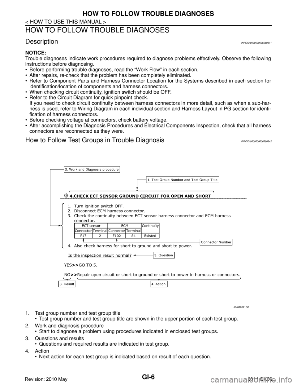
1. Test group number and test group title
Test group number and test group title are s hown in the upper portion of each test group.
2. Work and diagnosis procedure Start to diagnose a problem using procedur es indicated in enclosed test groups.
3. Questions and results Questions and required results are indicated in test group.
4. Action Next action for each test group is indicated based on result of each question.
JPAIA0021GB
Revision: 2010 May2011 QX56
Page 2992 of 5598

GI-28
< PRECAUTION >
PRECAUTIONS
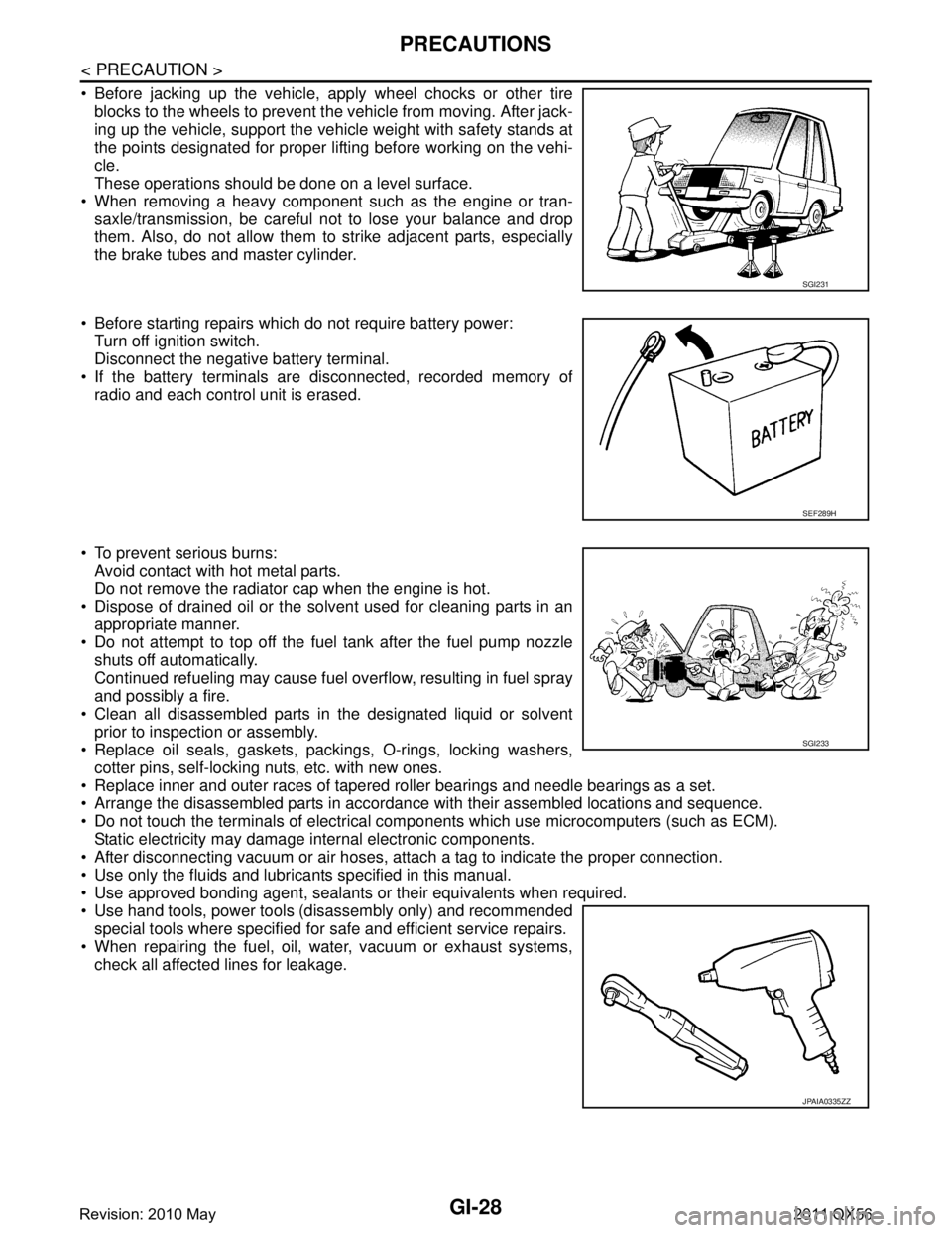
Before jacking up the vehicle, apply wheel chocks or other tireblocks to the wheels to prevent t he vehicle from moving. After jack-
ing up the vehicle, support the vehicle weight with safety stands at
the points designated for proper lifting before working on the vehi-
cle.
These operations should be done on a level surface.
When removing a heavy component such as the engine or tran- saxle/transmission, be careful not to lose your balance and drop
them. Also, do not allow them to strike adjacent parts, especially
the brake tubes and master cylinder.
Before starting repairs which do not require battery power: Turn off ignition switch.
Disconnect the negative battery terminal.
If the battery terminals are disconnected, recorded memory of
radio and each control unit is erased.
To prevent serious burns: Avoid contact with hot metal parts.
Do not remove the radiator cap when the engine is hot.
Dispose of drained oil or the solvent used for cleaning parts in an appropriate manner.
Do not attempt to top off the fuel tank after the fuel pump nozzle
shuts off automatically.
Continued refueling may cause fuel overflow, resulting in fuel spray
and possibly a fire.
Clean all disassembled parts in the designated liquid or solvent prior to inspection or assembly.
Replace oil seals, gaskets, packings, O-rings, locking washers,
cotter pins, self-locking nuts, etc. with new ones.
Replace inner and outer races of tapered roller bearings and needle bearings as a set.
Arrange the disassembled parts in accordance with their assembled locations and sequence.
Do not touch the terminals of electrical com ponents which use microcomputers (such as ECM).
Static electricity may damage internal electronic components.
After disconnecting vacuum or air hoses, atta ch a tag to indicate the proper connection.
Use only the fluids and lubricants specified in this manual.
Use approved bonding agent, sealants or their equivalents when required.
Use hand tools, power tools (disassembly only) and recommended special tools where specified for safe and efficient service repairs.
When repairing the fuel, oil, water, vacuum or exhaust systems, check all affected lines for leakage.
SGI231
SEF289H
SGI233
JPAIA0335ZZ
Revision: 2010 May2011 QX56