2011 INFINITI QX56 battery location
[x] Cancel search: battery locationPage 4468 of 5598
COMPONENT PARTSSE-9
< SYSTEM DESCRIPTION >
C
DE
F
G H
I
K L
M A
B
SE
N
O P
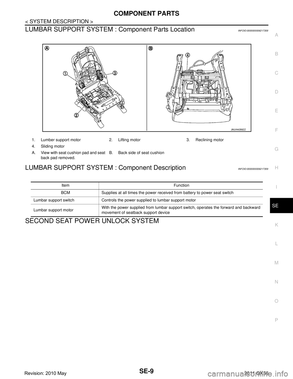
LUMBAR SUPPORT SYSTEM : Component Parts LocationINFOID:0000000006217358
LUMBAR SUPPORT SYSTEM : Component DescriptionINFOID:0000000006217359
SECOND SEAT POWER UNLOCK SYSTEM
1. Lumber support motor 2. Lifting motor 3. Reclining motor
4. Sliding motor
A. View with seat cushion pad and seat
back pad removed. B. Back side of seat cushion
JMJIA4288ZZ
Item Function
BCM Supplies at all times the power received from battery to power seat switch
Lumbar support switch Controls the power supplied to lumbar support motor
Lumbar support motor With the power supplied from lumbar support switch, operates the forward and backward
movement of seatback support device
Revision: 2010 May2011 QX56
Page 4469 of 5598

SE-10
< SYSTEM DESCRIPTION >
COMPONENT PARTS
SECOND SEAT POWER UNLOCK SYST EM : Component Parts Location
INFOID:0000000006217360
SECOND SEAT POWER UNLOCK SYSTEM : Component DescriptionINFOID:0000000006217361
THIRD SEAT SEATBACK POWER FOLDING SYSTEM
1. Power unlock motor RH 2. Power unlock relay RH 3. Second seat power unlock switch RH
4. Second seat power unlock switch LH 5. Power unlock motor LH 6. Power unlock relay LH
A. View with seat cushion pad and seat
back pad removed. B. View with seat cushion pad and seat
back pad removed.
JMJIA4221ZZ
Item Function
Second seat unlock switch supplies power supply to power unlock relay and operates power unlock system. Power unlock relay Supplies battery power supply to motor when receiving power supply from power unlock switch.
Power unlock motor Releases lock when receiving battery power supply from power unlock relay.
Revision: 2010 May2011 QX56
Page 4471 of 5598
SE-12
< SYSTEM DESCRIPTION >
COMPONENT PARTS
FRONT HEATED SEAT SYSTEM
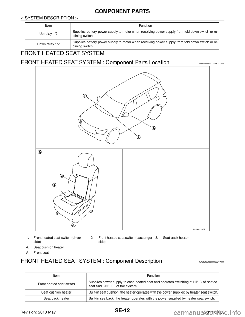
FRONT HEATED SEAT SYSTEM : Component Parts LocationINFOID:0000000006217364
FRONT HEATED SEAT SYSTEM : Component DescriptionINFOID:0000000006217365
Up relay 1/2Supplies battery power supply to motor when receiving power supply from fold down switch or re-
clining switch.
Down relay 1/2 Supplies battery power supply to motor when receiving power supply from fold down switch or re-
clining switch.
Item Function
JMJIA4223ZZ
1. Front heated seat switch (driver
side) 2. Front heated seat switch (passenger
side) 3. Seat back heater
4. Seat cushion heater
A. Front seat
Item Function
Front heated seat switch Supplies power supply to each heated seat and operates switching of HI/LO of heated
seat and ON/OFF of the system.
Seat cushion heater Built-in seat cushion, the heater operates with the power supplied by heater seat switch. Seat back heater Built-in seatback, the heater operates with the power supplied by heater seat switch.
Revision: 2010 May2011 QX56
Page 4608 of 5598

SEC-1
BODY EXTERIOR, DOORS, ROOF & VEHICLE SECURITY
C
D
E
F
G H
I
J
L
M
SECTION SEC
A
B
SEC
N
O P
CONTENTS
SECURITY CONTROL SYSTEM
WITH INTELLIGE NT KEY SYSTEM
PRECAUTION ................ ...............................
5
PRECAUTIONS .............................................. .....5
Precaution for Supplemental Restraint System
(SRS) "AIR BAG" and "SEAT BELT PRE-TEN-
SIONER" ............................................................. ......
5
Precaution Necessary for Steering Wheel Rota-
tion after Battery Disconnect .....................................
5
Precaution for Procedure without Cowl Top Cover ......6
SYSTEM DESCRIPTION ..............................7
COMPONENT PARTS ................................... .....7
Component Parts Location .................................. ......7
Component Description .............................................8
A/T Shift Selector (Detention Switch) ........................8
BCM ..........................................................................8
ECM ..........................................................................9
IPDM E/R ..................................................................9
NATS Antenna Amp. .................................................9
TCM ..........................................................................9
Combination Meter ....................................................9
Door Switch ...............................................................9
Hood Switch ..............................................................9
Inside Key Antenna ...................................................9
Intelligent Key ............................................................9
Push-button Ignition Switch .....................................10
Remote Keyless Entry Receiver .............................10
Security Indicator Lamp ..........................................10
Starter Control Relay ...............................................10
Starter Relay ...........................................................10
Steering Lock Relay ................................................10
Steering Lock Unit ...................................................10
Stop Lamp Switch ...................................................10
Transmission Range Switch ....................................10
Vehicle Information Display .....................................11
SYSTEM .............................................................12
INTELLIGENT KEY SYSTEM/ENGINE START
FUNCTION ............................................................. ....
12
INTELLIGENT KEY SYSTEM/ENGINE START
FUNCTION : System Diagram ................................
12
INTELLIGENT KEY SYSTEM/ENGINE START
FUNCTION : System Description ............................
12
INFINITI VEHICLE IMMOBILIZER SYSTEM-NATS ....14
INFINITI VEHICLE IMMOBILIZER SYSTEM-
NATS : System Diagram .........................................
15
INFINITI VEHICLE IMMOBILIZER SYSTEM-
NATS : System Description .....................................
15
VEHICLE SECURITY SYSTEM .................................17
VEHICLE SECURITY SYSTEM : System Dia-
gram .................................................................... ....
17
VEHICLE SECURITY SYSTEM : System Descrip-
tion ...........................................................................
18
DIAGNOSIS SYSTEM (BCM) ...........................21
COMMON ITEM ..................................................... ....21
COMMON ITEM : CONSULT-III Function (BCM -
COMMON ITEM) .....................................................
21
INTELLIGENT KEY ................................................ ....22
INTELLIGENT KEY : CONSULT-III Function
(BCM - INTELLIGENT KEY) ....................................
22
THEFT ALM ........................................................... ....26
THEFT ALM : CONSULT-III Function (BCM -
THEFT) ................................................................ ....
26
IMMU ...................................................................... ....27
IMMU : CONSULT-III Function (BCM - IMMU) ........27
DIAGNOSIS SYSTEM (IPDM E/R) ...................28
CONSULT-III Function (IPDM E/R) .........................28
ECU DIAGNOSIS INFORMATION ..............30
ECM, IPDM E/R, BCM .......................................30
List of ECU Reference ......................................... ....30
Revision: 2010 May2011 QX56
Page 4988 of 5598

ST-1
STEERING
C
DE
F
H I
J
K L
M
SECTION ST
A
B
ST
N
O P
CONTENTS
STEERING SYSTEM
PRECAUTION ................ ...............................3
PRECAUTIONS .............................................. .....3
Precaution for Supplemental Restraint System
(SRS) "AIR BAG" and "SEAT BELT PRE-TEN-
SIONER" ............................................................. ......
3
Precaution Necessary for Steering Wheel Rota-
tion after Battery Disconnect .....................................
3
Service Notice or Precautions for Steering System
......
4
PREPARATION ............................................5
PREPARATION .............................................. .....5
Special Service Tools .......................................... ......5
Commercial Service Tools ........................................6
SYSTEM DESCRIPTION ..............................7
COMPONENT PARTS ................................... .....7
Component Parts Location (Heated Steering
Wheel) ................................................................. ......
7
Component Description (Heated Steering Wheel) ......7
Heated Steering Wheel .............................................7
Heated Steering Wheel Switch .................................8
Heated Steering Wheel Relay ...................................8
SYSTEM ..............................................................9
System Description (Heated Steering Wheel) ..... ......9
WIRING DIAGRAM ......................................10
HEATED STEERING WHEEL ........................ ....10
Wiring Diagram ................................................... ....10
BASIC INSPECTION ...................................13
DIAGNOSIS AND REPAIR WORK FLOW .... ....13
WorkFlow (Heated Steering Wheel) .................... ....13
STEERING WHEEL ............................................14
Inspection ............................................................ ....14
DTC/CIRCUIT DIAGNOSIS .........................16
HEATED STEERING WHEEL SYSTEM ...........16
Component Function Check ................................ ....16
Diagnosis Procedure ...............................................16
Component Inspection (Heated Steering Wheel) ....18
Component Inspection (Heated Steering Wheel
Relay) ......................................................................
19
HEATED STEERING WHEEL SWITCH INDI-
CATOR LAMP ...................................................
20
Component Function Check ....................................20
Diagnosis Procedure ...............................................20
Component Inspection (Heated Steering Wheel
Relay) ......................................................................
22
SYMPTOM DIAGNOSIS ..............................23
HEATED STEERING WHEEL SYSTEM DOES
NOT ACTIVATE ................................................
23
Description ........................................................... ....23
Diagnosis Procedure ...............................................23
HEATED STEERING WHEEL SWITCH INDI-
CATOR LAMP DOES NOT TURN ON ..............
26
Description ...............................................................26
Diagnosis Procedure ...............................................26
NOISE, VIBRATION AND HARSHNESS
(NVH) TROUBLESHOOTING ...........................
29
NVH Troubleshooting Chart ....................................29
PERIODIC MAINTENANCE ........................30
POWER STEERING FLUID ..............................30
Inspection ............................................................ ....30
STEERING WHEEL ..........................................32
Inspection ................................................................32
REMOVAL AND INSTALLATION ...............33
Revision: 2010 May2011 QX56
Page 5003 of 5598
ST-16
< DTC/CIRCUIT DIAGNOSIS >
HEATED STEERING WHEEL SYSTEM
DTC/CIRCUIT DIAGNOSIS
HEATED STEERING WHEEL SYSTEM
Component Function CheckINFOID:0000000006225585
1.CHECK HEATED STEERING WHEEL SYSTEM
Check operate heated steering wheel system. Refer to ST-9, "
System Description (Heated Steering Wheel)".
Is the inspection result normal?
YES >> Go to ST-16, "Diagnosis Procedure".
NO >> INSPECTION END
Diagnosis ProcedureINFOID:0000000006225586
1.CHECK POWER SOURCE AND GROUND CIRCUIT
1. Turn ignition switch OFF.
2. Remove the heated steering wheel. Refer to ST-33, "
Removal and Installation".
3. Turn ignition switch ON.
CAUTION:
Never start the engine.
4. Turn heated steering wheel switch ON.
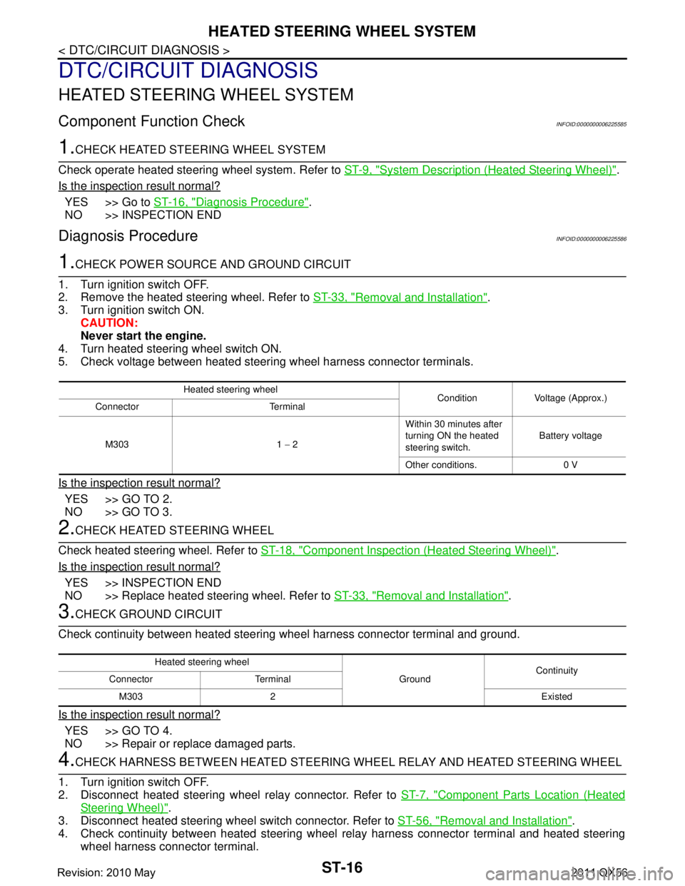
5. Check voltage between heated steering wheel harness connector terminals.
Is the inspection result normal?
YES >> GO TO 2.
NO >> GO TO 3.
2.CHECK HEATED STEERING WHEEL
Check heated steering wheel. Refer to ST-18, "
Component Inspection (Heated Steering Wheel)".
Is the inspection result normal?
YES >> INSPECTION END
NO >> Replace heated steering wheel. Refer to ST-33, "
Removal and Installation".
3.CHECK GROUND CIRCUIT
Check continuity between heated steering wheel harness connector terminal and ground.
Is the inspection result normal?
YES >> GO TO 4.
NO >> Repair or replace damaged parts.
4.CHECK HARNESS BETWEEN HEATED STEERING WHEEL RELAY AND HEATED STEERING WHEEL
1. Turn ignition switch OFF.
2. Disconnect heated steering wheel relay connector. Refer to ST-7, "
Component Parts Location (Heated
Steering Wheel)".
3. Disconnect heated steering wheel switch connector. Refer to ST-56, "
Removal and Installation".
4. Check continuity between heated steering wheel relay harness connector terminal and heated steering
wheel harness connector terminal.
Heated steering wheel Condition Voltage (Approx.)
Connector Terminal
M303 1 − 2 Within 30 minutes after
turning ON the heated
steering switch.
Battery voltage
Other conditions. 0 V
Heated steering wheel GroundContinuity
Connector Terminal
M303 2 Existed
Revision: 2010 May2011 QX56
Page 5004 of 5598
HEATED STEERING WHEEL SYSTEMST-17
< DTC/CIRCUIT DIAGNOSIS >
C
DE
F
H I
J
K L
M A
B
ST
N
O P
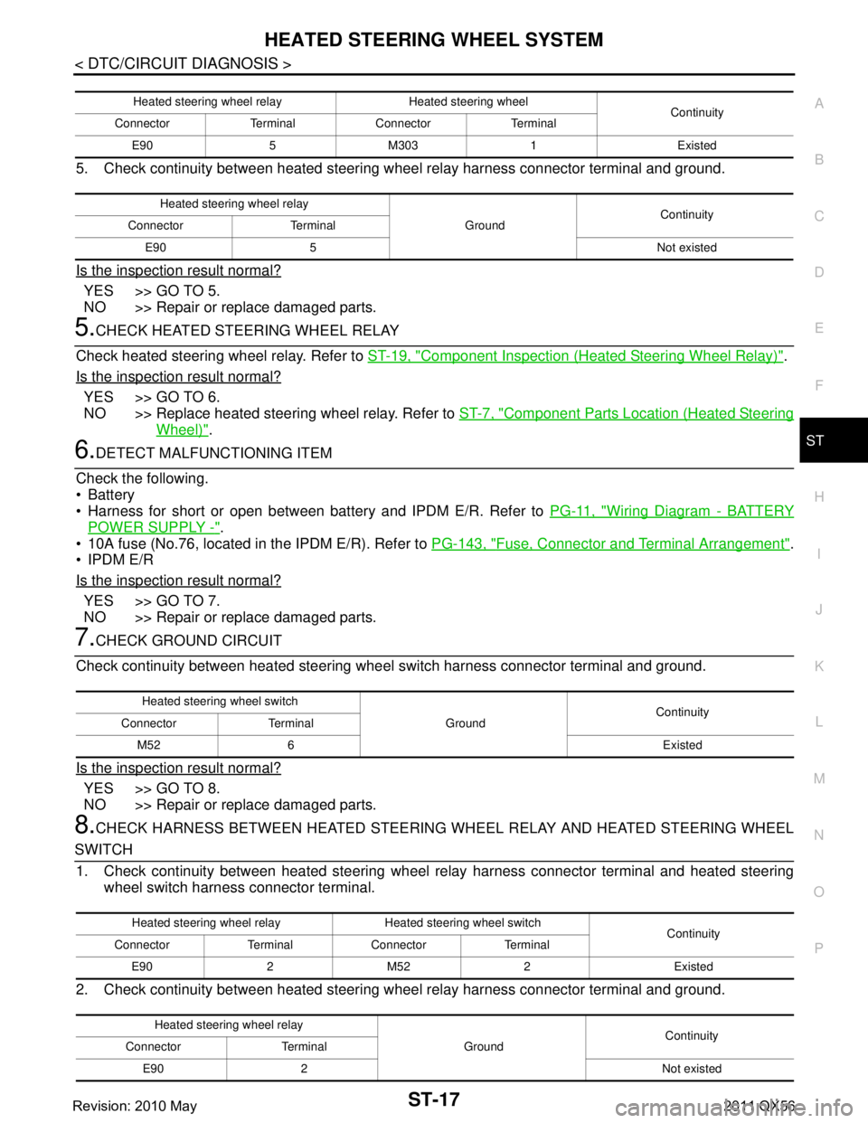
5. Check continuity between heated steering w heel relay harness connector terminal and ground.
Is the inspection result normal?
YES >> GO TO 5.
NO >> Repair or replace damaged parts.
5.CHECK HEATED STEERING WHEEL RELAY
Check heated steering wheel relay. Refer to ST-19, "
Component Inspection (Heated Steering Wheel Relay)".
Is the inspection result normal?
YES >> GO TO 6.
NO >> Replace heated steering wheel relay. Refer to ST-7, "
Component Parts Location (Heated Steering
Wheel)".
6.DETECT MALFUNCTIONING ITEM
Check the following.
Battery
Harness for short or open between bat tery and IPDM E/R. Refer to PG-11, "
Wiring Diagram - BATTERY
POWER SUPPLY -".
10A fuse (No.76, located in the IPDM E/R). Refer to PG-143, "
Fuse, Connector and Terminal Arrangement".
IPDM E/R
Is the inspection result normal?
YES >> GO TO 7.
NO >> Repair or replace damaged parts.
7.CHECK GROUND CIRCUIT
Check continuity between heated steering wheel switch harness connector terminal and ground.
Is the inspection result normal?
YES >> GO TO 8.
NO >> Repair or replace damaged parts.
8.CHECK HARNESS BETWEEN HEATED STEERING WHEEL RELAY AND HEATED STEERING WHEEL
SWITCH 1. Check continuity between heated steering wheel relay harness connector terminal and heated steering
wheel switch harness connector terminal.
2. Check continuity between heated steering w heel relay harness connector terminal and ground.
Heated steering wheel relay Heated steering wheel
Continuity
Connector Terminal Connector Terminal
E90 5 M303 1 Existed
Heated steering wheel relay GroundContinuity
Connector Terminal
E90 5 Not existed
Heated steering wheel switch GroundContinuity
Connector Terminal
M52 6 Existed
Heated steering wheel relay Heated steering wheel switch Continuity
Connector Terminal Connector Terminal
E90 2 M52 2 Existed
Heated steering wheel relay GroundContinuity
Connector Terminal
E90 2 Not existed
Revision: 2010 May2011 QX56
Page 5007 of 5598
ST-20
< DTC/CIRCUIT DIAGNOSIS >
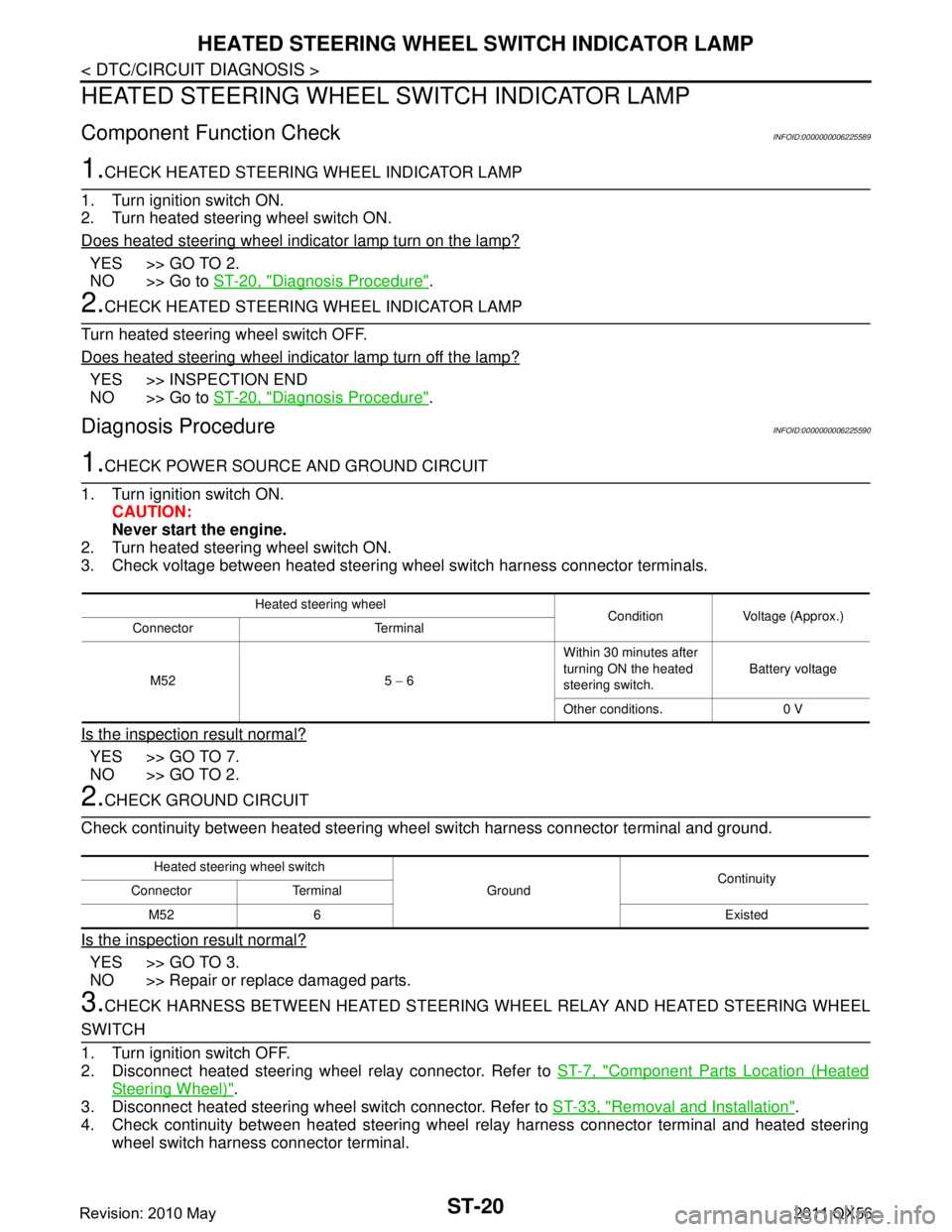
HEATED STEERING WHEEL SWITCH INDICATOR LAMP
HEATED STEERING WHEEL SWITCH INDICATOR LAMP
Component Function CheckINFOID:0000000006225589
1.CHECK HEATED STEERING WHEEL INDICATOR LAMP
1. Turn ignition switch ON.
2. Turn heated steering wheel switch ON.
Does heated steering wheel indicator lamp turn on the lamp?
YES >> GO TO 2.
NO >> Go to ST-20, "
Diagnosis Procedure".
2.CHECK HEATED STEERING WHEEL INDICATOR LAMP
Turn heated steering wheel switch OFF.
Does heated steering wheel indicator lamp turn off the lamp?
YES >> INSPECTION END
NO >> Go to ST-20, "
Diagnosis Procedure".
Diagnosis ProcedureINFOID:0000000006225590
1.CHECK POWER SOURCE AND GROUND CIRCUIT
1. Turn ignition switch ON. CAUTION:
Never start the engine.
2. Turn heated steering wheel switch ON.
3. Check voltage between heated steering wheel switch harness connector terminals.
Is the inspection result normal?
YES >> GO TO 7.
NO >> GO TO 2.
2.CHECK GROUND CIRCUIT
Check continuity between heated steering wheel switch harness connector terminal and ground.
Is the inspection result normal?
YES >> GO TO 3.
NO >> Repair or replace damaged parts.
3.CHECK HARNESS BETWEEN HEATED STEERING WHEEL RELAY AND HEATED STEERING WHEEL
SWITCH
1. Turn ignition switch OFF.
2. Disconnect heated steering wheel relay connector. Refer to ST-7, "
Component Parts Location (Heated
Steering Wheel)".
3. Disconnect heated steering wheel switch connector. Refer to ST-33, "
Removal and Installation".
4. Check continuity between heated steering wheel relay harness connector terminal and heated steering
wheel switch harness connector terminal.
Heated steering wheel Condition Voltage (Approx.)
Connector Terminal
M52 5 − 6 Within 30 minutes after
turning ON the heated
steering switch.
Battery voltage
Other conditions. 0 V
Heated steering wheel switch GroundContinuity
Connector Terminal
M52 6 Existed
Revision: 2010 May2011 QX56