2011 INFINITI QX56 battery location
[x] Cancel search: battery locationPage 5451 of 5598

WT-1
SUSPENSION
C
DF
G H
I
J
K L
M
SECTION WT
A
B
WT
N
O PCONTENTS
ROAD WHEELS & TIRES
PRECAUTION ................ ...............................3
PRECAUTIONS .............................................. .....3
Precaution for Supplemental Restraint System
(SRS) "AIR BAG" and "SEAT BELT PRE-TEN-
SIONER" ............................................................. ......
3
Precaution Necessary for Steering Wheel Rota-
tion after Battery Disconnect .....................................
3
Service Notice or Precautions for TPMS ...................4
Service Notice or Precautions for Road Wheel .........4
PREPARATION ............................................5
PREPARATION .............................................. .....5
Special Service Tools .......................................... ......5
Commercial Service Tools ........................................5
SYSTEM DESCRIPTION ..............................6
COMPONENT PARTS ................................... .....6
Component Parts Location .................................. ......6
Component Description .............................................7
Low Tire Pressure Warning Control Unit ...................7
Transmitter ................................................................7
Tire Pressure Receiver .............................................8
Low Tire Pressure Warning Lamp .............................8
SYSTEM ..............................................................9
System Description ............................................. ......9
Tire Inflation Indicator Function ...............................10
DIAGNOSIS SYSTEM (LOW TIRE PRES-
SURE WARNING CONTROL UNIT) ..................
12
CONSULT-III Function ........................................ ....12
ECU DIAGNOSIS INFORMATION ..............14
LOW TIRE PRESSURE WARNING CON-
TROL UNIT ..................................................... ....
14
Reference Value ................................................. ....14
DTC Inspection Priority Chart .................................17
DTC Index ...............................................................18
WIRING DIAGRAM ......................................19
TIRE PRESSURE MONITORING SYSTEM ......19
Wiring Diagram .................................................... ....19
BASIC INSPECTION ...................................25
DIAGNOSIS AND REPAIR WORK FLOW .......25
Work Flow ............................................................ ....25
ADDITIONAL SERVICE WHEN REPLACING
LOW TIRE PRESSURE WARNING CON-
TROL UNIT ........................................................
27
Description ...............................................................27
Work Procedure .......................................................27
TRANSMITTER WAKE UP OPERATION .........28
Description ...............................................................28
Work Procedure .......................................................28
ID REGISTRATION ...........................................29
Description ...............................................................29
Work Procedure .......................................................29
DTC/CIRCUIT DIAGNOSIS .........................31
C1704, C1705, C1706, C1707 LOW TIRE
PRESSURE .......................................................
31
DTC Logic ............................................................ ....31
Diagnosis Procedure ...............................................31
C1708, C1709, C1710, C1711 TRANSMITTER
(NO DATA) ........................................................
33
DTC Logic ............................................................ ....33
Diagnosis Procedure ...............................................33
C1716, C1717, C1718, C1719 TRANSMITTER
(PRESSURE DATA) ..........................................
37
DTC Logic ............................................................ ....37
Diagnosis Procedure ...............................................37
C1728 RECEIVER ID ........................................39
Revision: 2010 May2011 QX56
Page 5510 of 5598

WT-60
< SYMPTOM DIAGNOSIS >
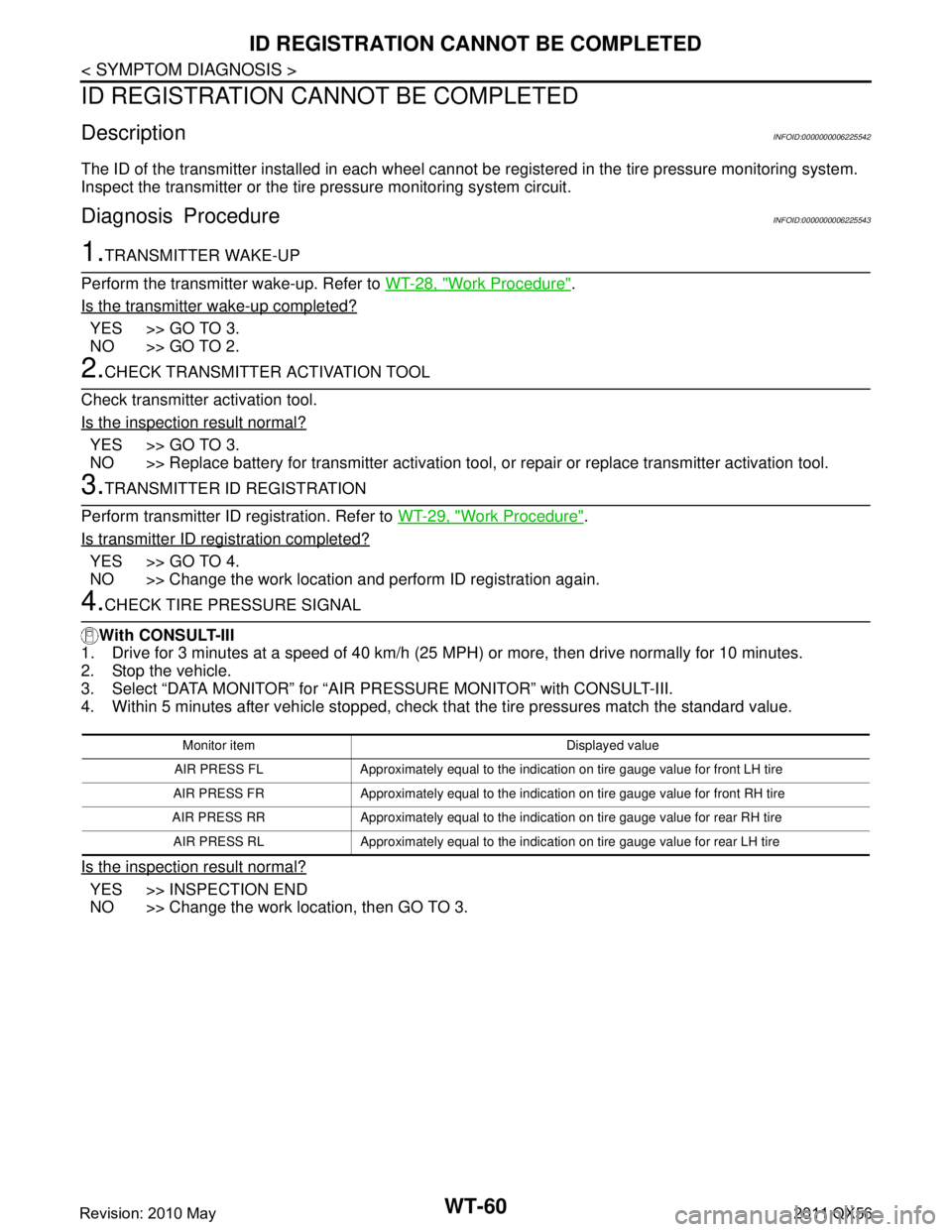
ID REGISTRATION CANNOT BE COMPLETED
ID REGISTRATION CANNOT BE COMPLETED
DescriptionINFOID:0000000006225542
The ID of the transmitter installed in each wheel cannot be registered in the tire pressure monitoring system.
Inspect the transmitter or the tire pressure monitoring system circuit.
Diagnosis ProcedureINFOID:0000000006225543
1.TRANSMITTER WAKE-UP
Perform the transmitter wake-up. Refer to WT-28, "
Work Procedure".
Is the transmitter wake-up completed?
YES >> GO TO 3.
NO >> GO TO 2.
2.CHECK TRANSMITTER ACTIVATION TOOL
Check transmitter activation tool.
Is the inspection result normal?
YES >> GO TO 3.
NO >> Replace battery for transmitter activation tool, or repair or replace transmitter activation tool.
3.TRANSMITTER ID REGISTRATION
Perform transmitter ID registration. Refer to WT-29, "
Work Procedure".
Is transmitter ID registration completed?
YES >> GO TO 4.
NO >> Change the work location and perform ID registration again.
4.CHECK TIRE PRESSURE SIGNAL
With CONSULT-III
1. Drive for 3 minutes at a speed of 40 km/h (25 MPH) or more, then drive normally for 10 minutes.
2. Stop the vehicle.
3. Select “DATA MONITOR” for “AIR PR ESSURE MONITOR” with CONSULT-III.
4. Within 5 minutes after vehicle stopped, check t hat the tire pressures match the standard value.
Is the inspection result normal?
YES >> INSPECTION END
NO >> Change the work location, then GO TO 3.
Monitor item Displayed value
AIR PRESS FL Approximately equal to the indication on tire gauge value for front LH tire
AIR PRESS FR Approximately equal to the indica tion on tire gauge value for front RH tire
AIR PRESS RR Approximately equal to the indica tion on tire gauge value for rear RH tire
AIR PRESS RL Approximately equal to the indicati on on tire gauge value for rear LH tire
Revision: 2010 May2011 QX56
Page 5520 of 5598

WW-1
DRIVER CONTROLS
C
DE
F
G H
I
J
K
M
SECTION WW
A
B
WW
N
O P
CONTENTS
WIPER & WASHER
PRECAUTION ................ ...............................3
PRECAUTIONS .............................................. .....3
Precaution for Supplemental Restraint System
(SRS) "AIR BAG" and "SEAT BELT PRE-TEN-
SIONER" ............................................................. ......
3
Precaution Necessary for Steering Wheel Rota-
tion after Battery Disconnect .....................................
3
Precaution for Procedure without Cowl Top Cover ......4
SYSTEM DESCRIPTION ..............................5
COMPONENT PARTS ................................... .....5
Component Parts Location .................................. ......5
Component Description ............................................6
Washer Switch ..........................................................6
SYSTEM ..............................................................7
FRONT WIPER AND WASHER SYSTEM ............. ......7
FRONT WIPER AND WASHER SYSTEM : Sys-
tem Diagram ..............................................................
7
FRONT WIPER AND WASHER SYSTEM : Sys-
tem Description .........................................................
7
FRONT WIPER AND WASHER SYSTEM : Fail-
safe ...........................................................................
9
REAR WIPER AND WASHER SYSTEM ............... ....10
REAR WIPER AND WASHER SYSTEM : System
Diagram ...................................................................
10
REAR WIPER AND WASHER SYSTEM : System
Description ..............................................................
10
REAR WIPER AND WASHER SYSTEM :
Fail Safe .................................................................
12
HEADLAMP WASHER SYSTEM .......................... ....12
HEADLAMP WASHER SYSTEM : System Dia-
gram ........................................................................
13
HEADLAMP WASHER SYSTEM : System De-
scription ...................................................................
13
DIAGNOSIS SYSTEM (BCM) ............................14
COMMON ITEM ..................................................... ....14
COMMON ITEM : CONSULT-III Function (BCM -
COMMON ITEM) .....................................................
14
WIPER .................................................................... ....15
WIPER : CONSULT-III Function (BCM - WIPER) ....15
DIAGNOSIS SYSTEM (IPDM E/R) ...................18
Diagnosis Description ..............................................18
CONSULT-III Function (IPDM E/R) .........................20
ECU DIAGNOSIS INFORMATION ..............23
BCM, IPDM E/R .................................................23
List of ECU Reference ......................................... ....23
WIRING DIAGRAM ......................................24
WIPER AND WASHER SYSTEM .....................24
Wiring Diagram .................................................... ....24
BASIC INSPECTION ...................................33
DIAGNOSIS AND REPAIR WORKFLOW ........33
Work Flow ............................................................ ....33
DTC/CIRCUIT DIAGNOSIS .........................35
WIPER AND WASHER FUSE ...........................35
Diagnosis Procedure ........................................... ....35
FRONT WIPER MOTOR LO CIRCUIT ..............36
Component Function Check ....................................36
Diagnosis Procedure ...............................................36
FRONT WIPER MOTOR HI CIRCUIT ...............37
Component Function Check ....................................37
Diagnosis Procedure ...............................................37
FRONT WIPER AUTO STOP SIGNAL CIR-
CUIT ..................................................................
38
Component Function Check ....................................38
Diagnosis Procedure ...............................................38
Revision: 2010 May2011 QX56