2011 INFINITI QX56 battery location
[x] Cancel search: battery locationPage 5009 of 5598
ST-22
< DTC/CIRCUIT DIAGNOSIS >
HEATED STEERING WHEEL SWITCH INDICATOR LAMP
7.DETECT MALFUNCTIONING ITEM
Check the following.
Ignition switch
Harness for short or open between ignition switch and fuse block (J/B). Refer to PG-11, "
Wiring Diagram -
BATTERY POWER SUPPLY -".
10A fuse [No.3, located in the fuse block (J/B)]. Refer to PG-143, "
Fuse, Connector and Terminal Arrange-
ment".
Fuse block (J/B)
Is the inspection result normal?
YES >> Replace heated steering wheel switch. Refer to ST-56, "Removal and Installation".
NO >> Repair or replace damaged parts.
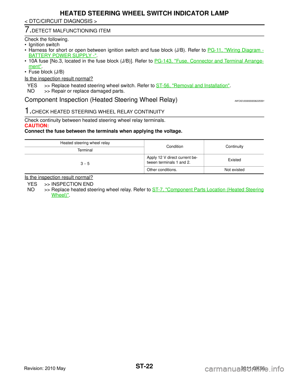
Component Inspection (H eated Steering Wheel Relay)INFOID:0000000006225591
1.CHECK HEATED STEERING WHEEL RELAY CONTINUITY
Check continuity between heated steering wheel relay terminals.
CAUTION:
Connect the fuse between the termi nals when applying the voltage.
Is the inspection result normal?
YES >> INSPECTION END
NO >> Replace heated steering wheel relay. Refer to ST-7, "
Component Parts Location (Heated Steering
Wheel)".
Heated steering wheel relay
Condition Continuity
Terminal
3 − 5 Apply 12 V direct current be-
tween terminals 1 and 2.
Existed
Other conditions. Not existed
Revision: 2010 May2011 QX56
Page 5010 of 5598
HEATED STEERING WHEEL SYSTEM DOES NOT ACTIVATE
ST-23
< SYMPTOM DIAGNOSIS >
C
D E
F
H I
J
K L
M A
B
ST
N
O P
SYMPTOM DIAGNOSIS
HEATED STEERING WHEEL SYSTEM DOES NOT ACTIVATE
Description INFOID:0000000006225592
The heated steering wheel does not warm up.
The heated steering wheel system cannot be turned OFF.
Diagnosis ProcedureINFOID:0000000006225593
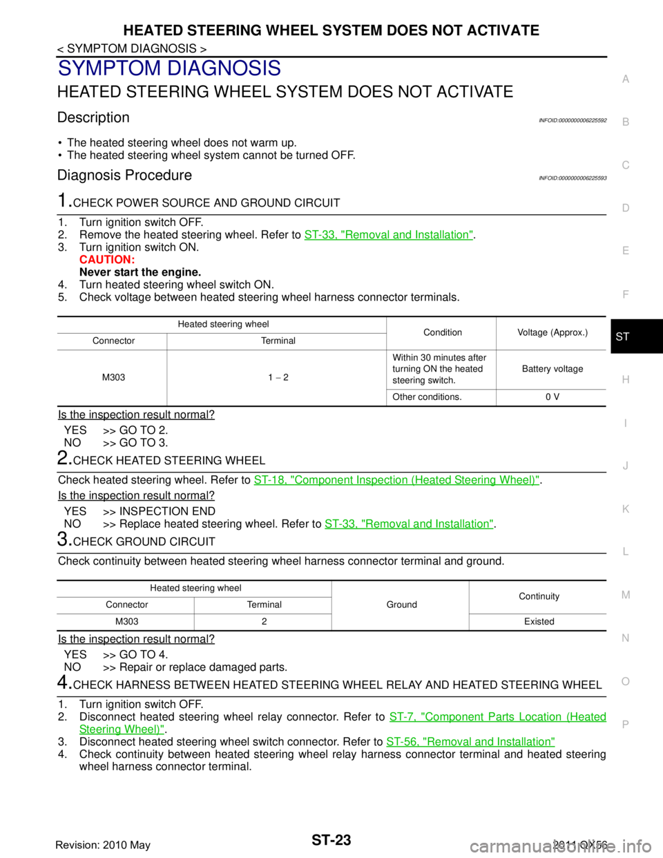
1.CHECK POWER SOURCE AND GROUND CIRCUIT
1. Turn ignition switch OFF.
2. Remove the heated steering wheel. Refer to ST-33, "
Removal and Installation".
3. Turn ignition switch ON.
CAUTION:
Never start the engine.
4. Turn heated steering wheel switch ON.
5. Check voltage between heated steering wheel harness connector terminals.
Is the inspection result normal?
YES >> GO TO 2.
NO >> GO TO 3.
2.CHECK HEATED STEERING WHEEL
Check heated steering wheel. Refer to ST-18, "
Component Inspection (Heated Steering Wheel)".
Is the inspection result normal?
YES >> INSPECTION END
NO >> Replace heated steering wheel. Refer to ST-33, "
Removal and Installation".
3.CHECK GROUND CIRCUIT
Check continuity between heated steering wheel harness connector terminal and ground.
Is the inspection result normal?
YES >> GO TO 4.
NO >> Repair or replace damaged parts.
4.CHECK HARNESS BETWEEN HEATED STEERING WHEEL RELAY AND HEATED STEERING WHEEL
1. Turn ignition switch OFF.
2. Disconnect heated steering wheel relay connector. Refer to ST-7, "
Component Parts Location (Heated
Steering Wheel)".
3. Disconnect heated steering wheel switch connector. Refer to ST-56, "
Removal and Installation"
4. Check continuity between heated steering wheel relay harness connector terminal and heated steering
wheel harness connector terminal.
Heated steering wheel Condition Voltage (Approx.)
Connector Terminal
M303 1 − 2 Within 30 minutes after
turning ON the heated
steering switch.
Battery voltage
Other conditions. 0 V
Heated steering wheel GroundContinuity
Connector Terminal
M303 2 Existed
Revision: 2010 May2011 QX56
Page 5011 of 5598
ST-24
< SYMPTOM DIAGNOSIS >
HEATED STEERING WHEEL SYSTEM DOES NOT ACTIVATE
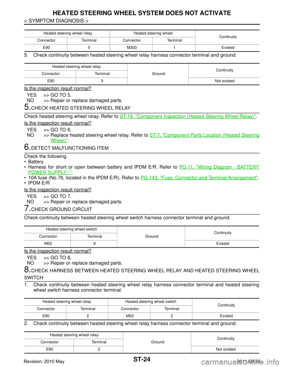
5. Check continuity between heated steering wheel relay harness connector terminal and ground.
Is the inspection result normal?
YES >> GO TO 5.
NO >> Repair or replace damaged parts.
5.CHECK HEATED STEERING WHEEL RELAY
Check heated steering wheel relay. Refer to ST-19, "
Component Inspection (Heated Steering Wheel Relay)".
Is the inspection result normal?
YES >> GO TO 6.
NO >> Replace heated steering wheel relay. Refer to ST-7, "
Component Parts Location (Heated Steering
Wheel)".
6.DETECT MALFUNCTIONING ITEM
Check the following.
Battery
Harness for short or open between bat tery and IPDM E/R. Refer to PG-11, "
Wiring Diagram - BATTERY
POWER SUPPLY -".
10A fuse (No.76, located in the IPDM E/R). Refer to PG-143, "
Fuse, Connector and Terminal Arrangement".
IPDM E/R
Is the inspection result normal?
YES >> GO TO 7.
NO >> Repair or replace damaged parts.
7.CHECK GROUND CIRCUIT
Check continuity between heated steering wheel switch harness connector terminal and ground.
Is the inspection result normal?
YES >> GO TO 8.
NO >> Repair or replace damaged parts.
8.CHECK HARNESS BETWEEN HEATED STEERING WHEEL RELAY AND HEATED STEERING WHEEL
SWITCH
1. Check continuity between heated steering wheel relay harness connector terminal and heated steering
wheel switch harness connector terminal.
2. Check continuity between heated steering w heel relay harness connector terminal and ground.
Heated steering wheel relay Heated steering wheel
Continuity
Connector Terminal Connector Terminal
E90 5 M303 1 Existed
Heated steering wheel relay GroundContinuity
Connector Terminal
E90 5 Not existed
Heated steering wheel switch GroundContinuity
Connector Terminal
M52 6 Existed
Heated steering wheel relay Heated steering wheel switch Continuity
Connector Terminal Connector Terminal
E90 2 M52 2 Existed
Heated steering wheel relay GroundContinuity
Connector Terminal
E90 2 Not existed
Revision: 2010 May2011 QX56
Page 5013 of 5598
ST-26
< SYMPTOM DIAGNOSIS >
HEATED STEERING WHEEL SWITCH INDICATOR LAMP DOES NOT TURN ON
HEATED STEERING WHEEL SWITCH INDICATOR LAMP DOES NOT
TURN ON
Description INFOID:0000000006225594
Heated steering wheel switch indicator lamp does not turn on the lamp.
Heated steering wheel switch indicator lamp does not turn off the lamp.
Diagnosis ProcedureINFOID:0000000006225595
1.CHECK POWER SOURCE AND GROUND CIRCUIT
1. Turn ignition switch ON. CAUTION:
Never start the engine.
2. Turn heated steering wheel switch ON.
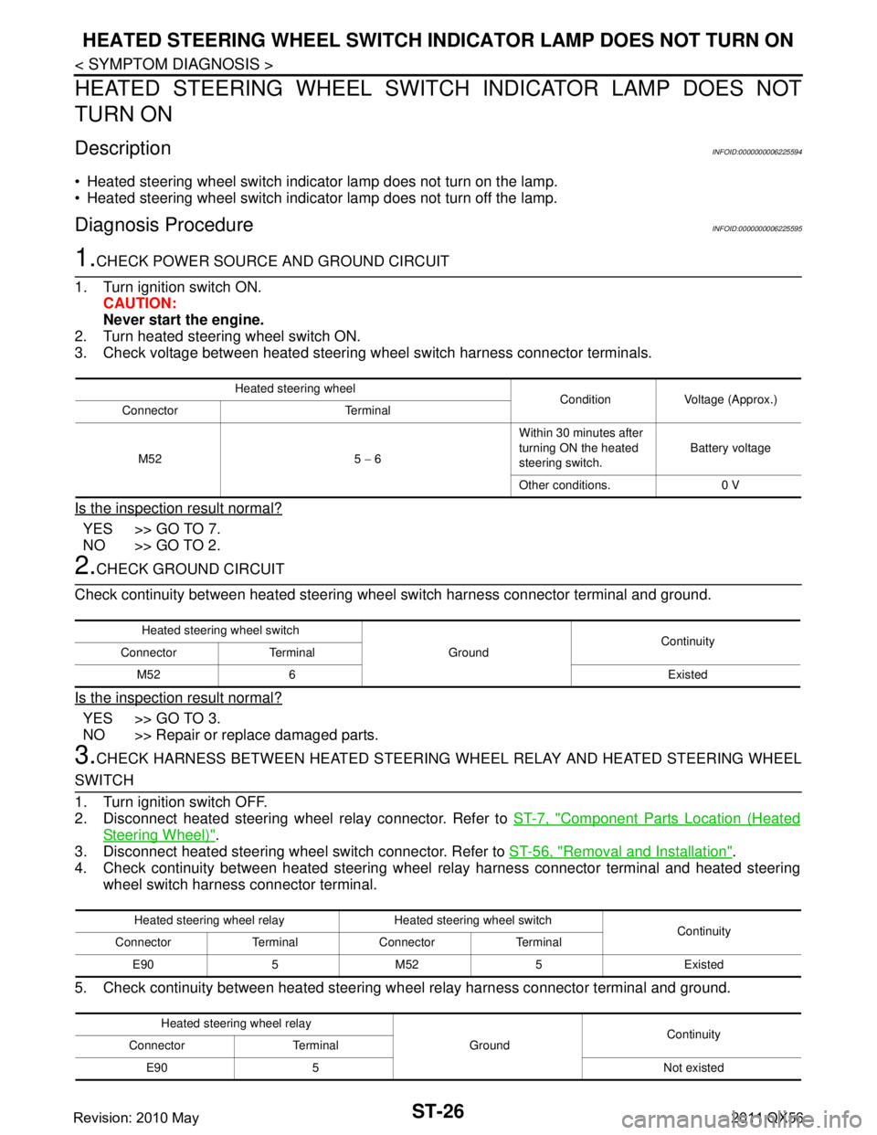
3. Check voltage between heated steering wheel switch harness connector terminals.
Is the inspection result normal?
YES >> GO TO 7.
NO >> GO TO 2.
2.CHECK GROUND CIRCUIT
Check continuity between heated steering wheel switch harness connector terminal and ground.
Is the inspection result normal?
YES >> GO TO 3.
NO >> Repair or replace damaged parts.
3.CHECK HARNESS BETWEEN HEATED STEERING WHEEL RELAY AND HEATED STEERING WHEEL
SWITCH
1. Turn ignition switch OFF.
2. Disconnect heated steering wheel relay connector. Refer to ST-7, "
Component Parts Location (Heated
Steering Wheel)".
3. Disconnect heated steering wheel switch connector. Refer to ST-56, "
Removal and Installation".
4. Check continuity between heated steering wheel relay harness connector terminal and heated steering
wheel switch harness connector terminal.
5. Check continuity between heated steering w heel relay harness connector terminal and ground.
Heated steering wheel
Condition Voltage (Approx.)
Connector Terminal
M52 5 − 6 Within 30 minutes after
turning ON the heated
steering switch.
Battery voltage
Other conditions. 0 V
Heated steering wheel switch GroundContinuity
Connector Terminal
M52 6 Existed
Heated steering wheel relay Heated steering wheel switch Continuity
Connector Terminal Connector Terminal
E90 5 M52 5 Existed
Heated steering wheel relay GroundContinuity
Connector Terminal
E90 5 Not existed
Revision: 2010 May2011 QX56
Page 5014 of 5598
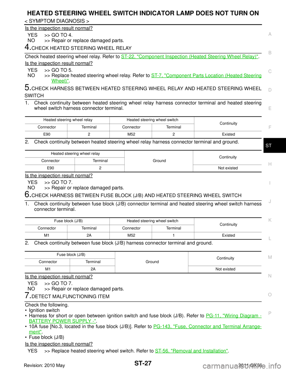
HEATED STEERING WHEEL SWITCH INDICATOR LAMP DOES NOT TURN ON
ST-27
< SYMPTOM DIAGNOSIS >
C
D E
F
H I
J
K L
M A
B
ST
N
O P
Is the inspection result normal?
YES >> GO TO 4.
NO >> Repair or replace damaged parts.
4.CHECK HEATED STEERING WHEEL RELAY
Check heated steering wheel relay. Refer to ST-22, "
Component Inspection (Heated Steering Wheel Relay)".
Is the inspection result normal?
YES >> GO TO 5.
NO >> Replace heated steering wheel relay. Refer to ST-7, "
Component Parts Location (Heated Steering
Wheel)".
5.CHECK HARNESS BETWEEN HEATED STEERING WHEEL RELAY AND HEATED STEERING WHEEL
SWITCH
1. Check continuity between heated steering wheel relay harness connector terminal and heated steering
wheel switch harness connector terminal.
2. Check continuity between heated steering w heel relay harness connector terminal and ground.
Is the inspection result normal?
YES >> GO TO 7.
NO >> Repair or replace damaged parts.
6.CHECK HARNESS BETWEEN FUSE BLOCK (J/B) AND HEATED STEERING WHEEL SWITCH
1. Check continuity between fuse block (J/B) connec tor terminal and heated steering wheel switch harness
connector terminal.
2. Check continuity between fuse block (J/B) harness connector terminal and ground.
Is the inspection result normal?
YES >> GO TO 7.
NO >> Repair or replace damaged parts.
7.DETECT MALFUNCTIONING ITEM
Check the following.
Ignition switch
Harness for short or open between ignition s witch and fuse block (J/B). Refer to PG-11, "
Wiring Diagram -
BATTERY POWER SUPPLY -".
10A fuse [No.3, located in the fuse block (J/B)]. Refer to PG-143, "
Fuse, Connector and Terminal Arrange-
ment".
Fuse block (J/B)
Is the inspection result normal?
YES >> Replace heated steering wheel switch. Refer to ST-56, "Removal and Installation".
Heated steering wheel relay Heated steering wheel switch
Continuity
Connector Terminal Connector Terminal
E90 2 M52 2 Existed
Heated steering wheel relay GroundContinuity
Connector Terminal
E90 2 Not existed
Fuse block (J/B) Heated steering wheel switch Continuity
Connector Terminal Connector Terminal
M1 2A M52 1 Existed
Fuse block (J/B) GroundContinuity
Connector Terminal
M1 2A Not existed
Revision: 2010 May2011 QX56
Page 5046 of 5598

STC-1
STEERING
C
DE
F
H I
J
K L
M
SECTION STC
A
B
STC
N
O P
CONTENTS
STEERING CONTROL SYSTEM
PRECAUTION ................ ...............................2
PRECAUTIONS .............................................. .....2
Precaution for Supplemental Restraint System
(SRS) "AIR BAG" and "SEAT BELT PRE-TEN-
SIONER" ............................................................. ......
2
Precaution Necessary for Steering Wheel Rota-
tion after Battery Disconnect .....................................
2
SYSTEM DESCRIPTION ..............................4
COMPONENT PARTS ................................... .....4
Component Parts Location .................................. ......4
Component Description .............................................4
Power Steering Control Unit ......................................4
Power Steering Solenoid Valve .................................4
SYSTEM ..............................................................5
EPS SYSTEM ........................................ ......................5
EPS SYSTEM : System De scription .........................5
EPS SYSTEM : Fail-Safe ..........................................6
ECU DIAGNOSIS INFO RMATION ...............8
POWER STEERING CONTROL UNIT ........... .....8
Reference Value ................................................. ......8
Fail-Safe ....................................................................9
WIRING DIAGRAM ......................................10
ELECTRONICALLY CONTROLLED POWER
STEERING SYSTEM ...................................... ....
10
Wiring Diagram ................................................... ....10
BASIC INSPECTION ...................................13
DIAGNOSIS AND REPAIR WORK FLOW .......13
Work Flow ............................................................ ....13
DTC/CIRCUIT DIAGNOSIS .........................14
POWER SUPPLY AND GROUND CIRCUIT ....14
Diagnosis Procedure ........................................... ....14
POWER STEERING SOLENOID VALVE .........16
Component Function Check ....................................16
Diagnosis Procedure ...............................................16
Component Inspection .............................................17
ENGINE SPEED SIGNAL CIRCUIT ..................18
Diagnosis Procedure ........................................... ....18
VEHICLE SPEED SIGNAL CIRCUIT ................20
Diagnosis Procedure ...............................................20
SYMPTOM DIAGNOSIS ..............................22
UNBALANCE STEERING WHEEL TURNING
FORCE (TORQUE VARIATION) .......................
22
Description ........................................................... ....22
Diagnosis Procedure ...............................................22
REMOVAL AND INSTALLATION ...............23
POWER STEERING CONTROL UNIT ..............23
Removal and Installation ..................................... ....23
Revision: 2010 May2011 QX56
Page 5069 of 5598

STR-1
ENGINE
C
DE
F
G H
I
J
K L
M
SECTION STR
A
STR
N
O P
CONTENTS
STARTING SYSTEM
PRECAUTION ................ ...............................2
PRECAUTIONS .............................................. .....2
Precaution for Supplemental Restraint System
(SRS) "AIR BAG" and "SEAT BELT PRE-TEN-
SIONER" ............................................................. ......
2
Precaution Necessary for Steering Wheel Rota-
tion after Battery Disconnect .....................................
2
PREPARATION ............................................4
PREPARATION .............................................. .....4
Special Service Tools .......................................... ......4
Commercial Service Tools ........................................4
SYSTEM DESCRIPTION ..............................5
COMPONENT PARTS ................................... .....5
Component Parts Location .................................. ......5
Component Description ............................................5
SYSTEM ..............................................................6
System Diagram .................................................. ......6
System Description ...................................................6
WIRING DIAGRAM .......................................7
STARTING SYSTEM ...................................... .....7
Wiring Diagram ................................................... ......7
BASIC INSPECTION ...................................11
DIAGNOSIS AND REPAIR WORKFLOW ........11
Work Flow ............................................................ ....11
DTC/CIRCUIT DIAGNOSIS .........................14
B TERMINAL CIRCUIT .....................................14
Diagnosis Procedure ........................................... ....14
S CONNECTOR CIRCUIT .................................15
Diagnosis Procedure ...............................................15
SYMPTOM DIAGNOSIS ..............................16
STARTING SYSTEM .........................................16
Symptom Table ................................................... ....16
REMOVAL AND INSTALLATION ...............17
STARTER MOTOR ...........................................17
Exploded View ..................................................... ....17
Removal and Installation .........................................18
Inspection ................................................................18
SERVICE DATA AND SPECIFICATIONS
(SDS) ............... .............................................
20
SERVICE DATA AND SPECIFICATIONS
(SDS) .................................................................
20
Starter Motor .......................................................
Revision: 2010 May2011 QX56
Page 5073 of 5598
COMPONENT PARTSSTR-5
< SYSTEM DESCRIPTION >
C
DE
F
G H
I
J
K L
M A
STR
NP
O
SYSTEM DESCRIPTION
COMPONENT PARTS
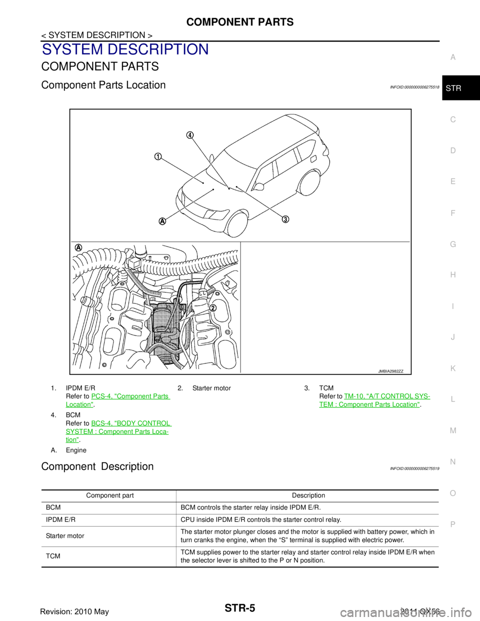
Component Parts LocationINFOID:0000000006275518
Component DescriptionINFOID:0000000006275519
1. IPDM E/R
Refer to PCS-4, "
Component Parts
Location". 2. Starter motor 3. TCM
Refer to TM-10, "
A/T CONTROL SYS-
TEM : Component Parts Location".
4. BCM Refer to BCS-4, "
BODY CONTROL
SYSTEM : Componen t Parts Loca-
tion".
A. Engine
JMBIA2982ZZ
Component part Description
BCM BCM controls the starter relay inside IPDM E/R.
IPDM E/R CPU inside IPDM E/R controls the starter control relay.
Starter motor The starter motor plunger closes and the motor is supplied with battery power, which in
turn cranks the engine, when the “S” terminal is supplied with electric power.
TCM TCM supplies power to the starter relay and starter control relay inside IPDM E/R when
the selector lever is shifted to the P or N position.
Revision: 2010 May2011 QX56