2011 INFINITI QX56 stop start
[x] Cancel search: stop startPage 3661 of 5598
![INFINITI QX56 2011 Factory Service Manual
LU-8
< PERIODIC MAINTENANCE >
ENGINE OIL
5. Install the oil pressure gauge [SST: ST25051001 (J25695-1)] (A)and hose [SST: ST25052000 (J25695-2)] (B).
6. Start the engine and warm it up to normal oper INFINITI QX56 2011 Factory Service Manual
LU-8
< PERIODIC MAINTENANCE >
ENGINE OIL
5. Install the oil pressure gauge [SST: ST25051001 (J25695-1)] (A)and hose [SST: ST25052000 (J25695-2)] (B).
6. Start the engine and warm it up to normal oper](/manual-img/42/57033/w960_57033-3660.png)
LU-8
< PERIODIC MAINTENANCE >
ENGINE OIL
5. Install the oil pressure gauge [SST: ST25051001 (J25695-1)] (A)and hose [SST: ST25052000 (J25695-2)] (B).
6. Start the engine and warm it up to normal operating temperature.
7. Check the engine oil pressure with engine running under no-load. Refer to LU-17, "
EngineOilPressure".
CAUTION:
If the difference is extreme, check the oil passages and oil pump for leaks and blockages.
8. After the inspections, install oil pressure switch as follows:
a. Remove old liquid gasket adhering to oil pressure switch and engine.
b. Apply liquid gasket and tighten oil pressure switch to the specification. Use Genuine RTV Silicone Seal ant or equivalent. Refer to GI-22, "
Recommended Chemical Prod-
ucts and Sealants".
c. After warming up engine, make sure there is no leakage of engine oil with engine running.
DrainingINFOID:0000000006289617
WARNING:
Be careful not to burn yourself, as th e engine and engine oil may be hot.
Prolonged and repeated contact with used engine oil may cause skin cancer; try to avoid direct skin
contact with used oil. If skin contact is made, wash thoroughly with soap or hand cleaner as soon as
possible.
1. Warm up the engine, and check for any oil leaks.
2. Stop the engine and wait for at least 10 minutes.
3. Remove drain plug and oil filler cap to drain the old oil.
RefillingINFOID:0000000006289618
1. Install drain plug with new washer. CAUTION:
Be sure to clean drain plug and install with new washer.
2. Refill with new engine oil. Engine oil specification and viscosity:
Refer to MA-10, "
Fluids and Lubricants".
CAUTION:
The refill capacity depends on the engine oi l temperature and drain time. Use these specifica-
tions for reference only.
Always use oil level gauge to determine the proper amount of engine oil in engine.
3. Warm up the engine and check area around drain plug and oil filter for engine oil leakage.
4. Stop the engine and wait for 10 minutes.
5. Check the engine oil level. Refer to LU-7, "
Inspection".
JPBIA0074ZZ
Oil pressure switch torque : Refer to EM-57, "Exploded View".
Tightening torque : Refer to EM-54, "
Exploded View".
Engine oil capacity : Refer to LU-17, "
Periodical Maintenance Specification".
Revision: 2010 May2011 QX56
Page 3662 of 5598
OIL FILTERLU-9
< PERIODIC MAINTENANCE >
C
DE
F
G H
I
J
K L
M A
LU
NP
O
OIL FILTER
Removal and InstallationINFOID:0000000006289619
REMOVAL
1. Remove front under cover.
2. Drain engine oil. Refer to
LU-8, "
Draining".
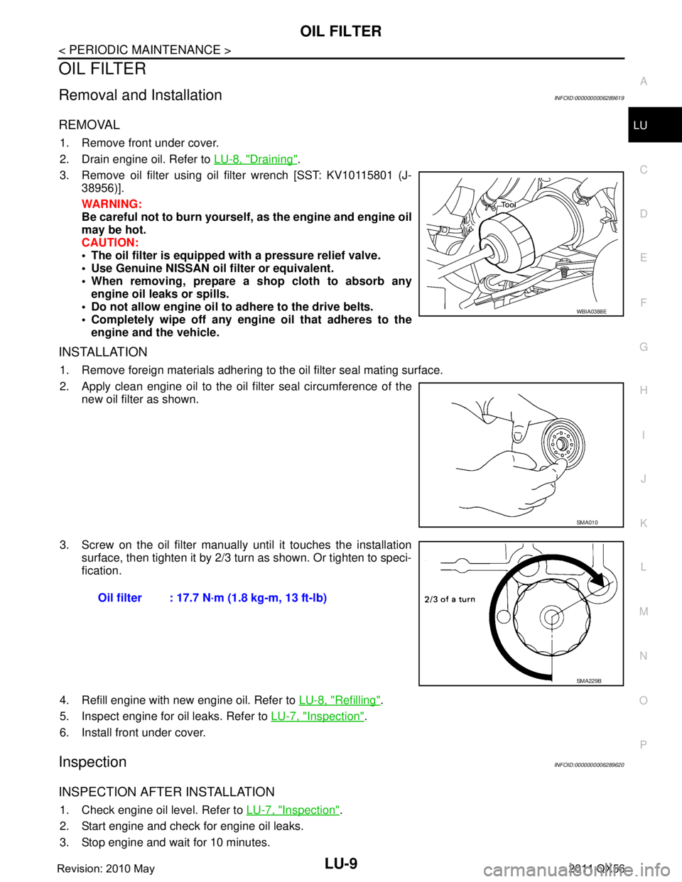
3. Remove oil filter using oil filter wrench [SST: KV10115801 (J- 38956)].
WARNING:
Be careful not to burn yourself, as the engine and engine oil
may be hot.
CAUTION:
The oil filter is equipped with a pressure relief valve.
Use Genuine NISSAN oil filter or equivalent.
When removing, prepare a s hop cloth to absorb any
engine oil leaks or spills.
Do not allow engine oil to adhere to the drive belts.
Completely wipe off any engine oil that adheres to the engine and the vehicle.
INSTALLATION
1. Remove foreign materials adhering to the oil filter seal mating surface.
2. Apply clean engine oil to the oil filter seal circumference of the
new oil filter as shown.
3. Screw on the oil filter manually until it touches the installation surface, then tighten it by 2/3 turn as shown. Or tighten to speci-
fication.
4. Refill engine with new engine oil. Refer to LU-8, "
Refilling".
5. Inspect engine for oil leaks. Refer to LU-7, "
Inspection".
6. Install front under cover.
InspectionINFOID:0000000006289620
INSPECTION AFTER INSTALLATION
1. Check engine oil level. Refer to LU-7, "Inspection".
2. Start engine and check for engine oil leaks.
3. Stop engine and wait for 10 minutes.
WBIA0388E
SMA010
Oil filter : 17.7 N·m (1.8 kg-m, 13 ft-lb)
SMA229B
Revision: 2010 May2011 QX56
Page 3665 of 5598
LU-12
< REMOVAL AND INSTALLATION >
OIL COOLER
CAUTION:
Perform this step when engine is cold.
4. Remove oil filter. Refer to LU-9, "
Removal and Installation".
5. Remove connector bolt, and remove oil cooler.
INSTALLATION
Installation is in the reverse order of removal, paying attention to the following:
Confirm that no foreign objects are adhering to the sealing surfaces of the oil cooler and oil pan.
InspectionINFOID:0000000006289623
INSPECTION AFTER REMOVAL
Oil Cooler
Check oil cooler for cracks. Check oil cooler for clogging by blowing compressed air through engine coolant
inlet. If necessary, replace oil cooler assembly.
Relief Valve
Inspect relief valve for movement, cracks and breaks by pushing the ball. If replacement is necessary, remove
the valve by prying it out using a suitable tool. Install a new valve in place by tapping it in.
INSPECTION AFTER INSTALLATION
1. Check engine oil and engine coolant levels and add engine oil and engine coolant. Refer to LU-7, "Inspec-
tion" and CO-8, "Inspection".
2. Start the engine, and check for l eaks of engine oil or engine coolant.
3. Stop the engine and wait for 10 minutes.
4. Check the engine oil level and engine coolant level again. Refer to LU-7, "
Inspection" and CO-8, "Inspec-
tion"
Revision: 2010 May2011 QX56
Page 3669 of 5598
LU-16
< REMOVAL AND INSTALLATION >
OIL PUMP
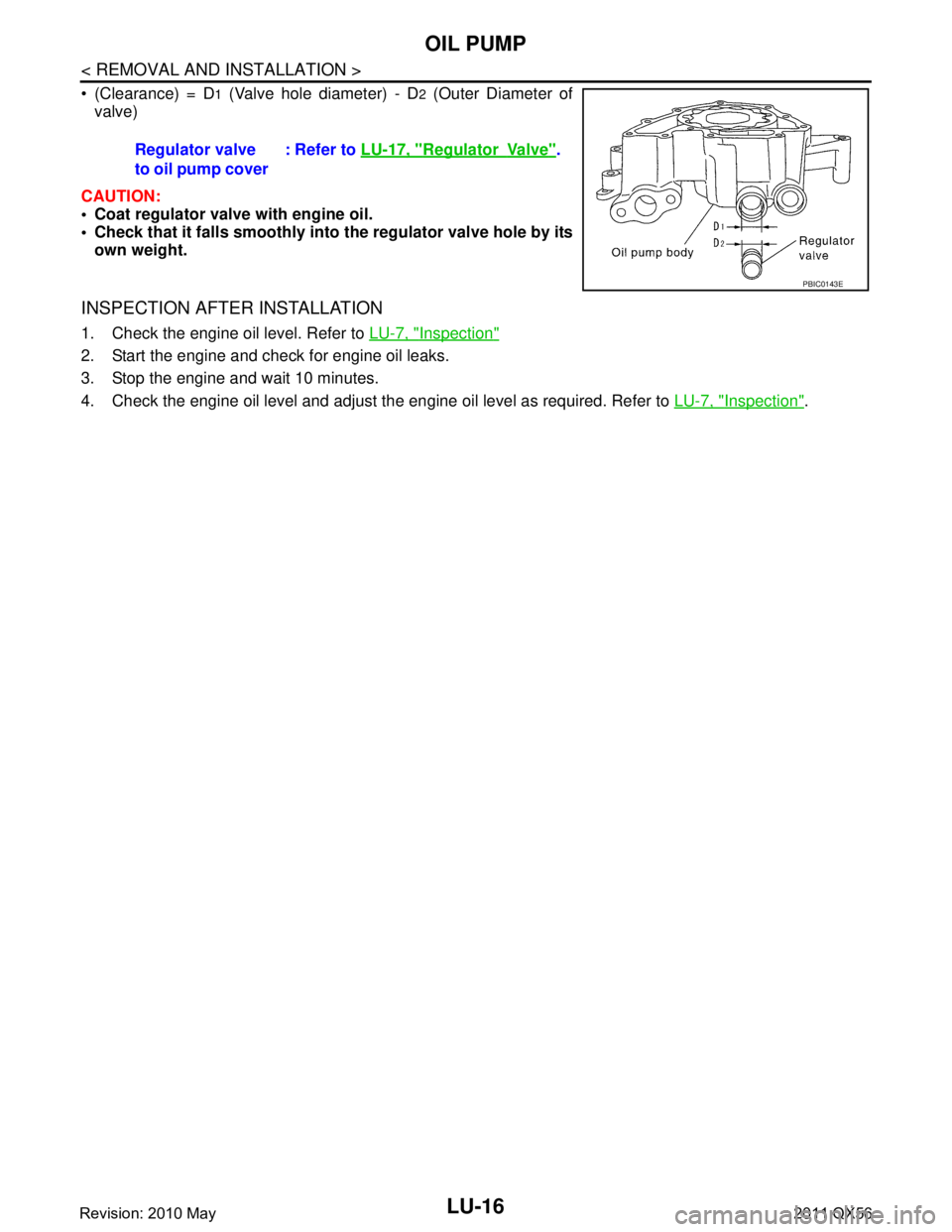
(Clearance) = D1 (Valve hole diameter) - D2 (Outer Diameter of
valve)
CAUTION:
Coat regulator valve with engine oil.
Check that it falls smoothly into the regulator valve hole by its
own weight.
INSPECTION AFTER INSTALLATION
1. Check the engine oil level. Refer to LU-7, "Inspection"
2. Start the engine and check for engine oil leaks.
3. Stop the engine and wait 10 minutes.
4. Check the engine oil level and adjust the engine oil level as required. Refer to LU-7, "
Inspection".
Regulator valve
to oil pump cover
: Refer to
LU-17, "
RegulatorVa l v e".
PBIC0143E
Revision: 2010 May2011 QX56
Page 3691 of 5598
CHASSIS MAINTENANCEMA-21
< PERIODIC MAINTENANCE >
C
DE
F
G H
I
J
K L
M B
MA
N
O A
CHASSIS MAINTENANCE
EXHAUST SYSTEM
EXHAUST SYSTEM : InspectionINFOID:0000000006220926
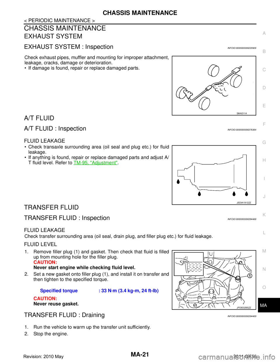
Check exhaust pipes, muffler and mounting for improper attachment,
leakage, cracks, damage or deterioration.
If damage is found, repair or replace damaged parts.
A/T FLUID
A/T FLUID : InspectionINFOID:0000000006376364
FLUID LEAKAGE
Check transaxle surrounding area (oil seal and plug etc.) for fluid
leakage.
If anything is found, repair or replace damaged parts and adjust A/ T fluid level. Refer to TM-95, "
Adjustment".
TRANSFER FLUID
TRANSFER FLUID : InspectionINFOID:0000000006394468
FLUID LEAKAGE
Check transfer surrounding area (oil seal, drain plug, and filler plug etc.) for fluid leakage.
FLUID LEVEL
1. Remove filler plug (1) and gasket. Then check that fluid is filled
up from mounting hole for the filler plug.
CAUTION:
Never start engine whil e checking fluid level.
2. Set a new gasket onto filler plug (1), and install it on transfer and then tighten to the specified torque.
CAUTION:
Never reuse gasket.
TRANSFER FLUID : DrainingINFOID:0000000006394469
1. Run the vehicle to warm up the transfer unit sufficiently.
2. Stop the engine.
SMA211A
JSDIA1912ZZ
Specified torque : 33 N·m (3.4 kg-m, 24 ft-lb)
JPDIE0295ZZ
Revision: 2010 May2011 QX56
Page 3694 of 5598
MA-24
< PERIODIC MAINTENANCE >
CHASSIS MAINTENANCE
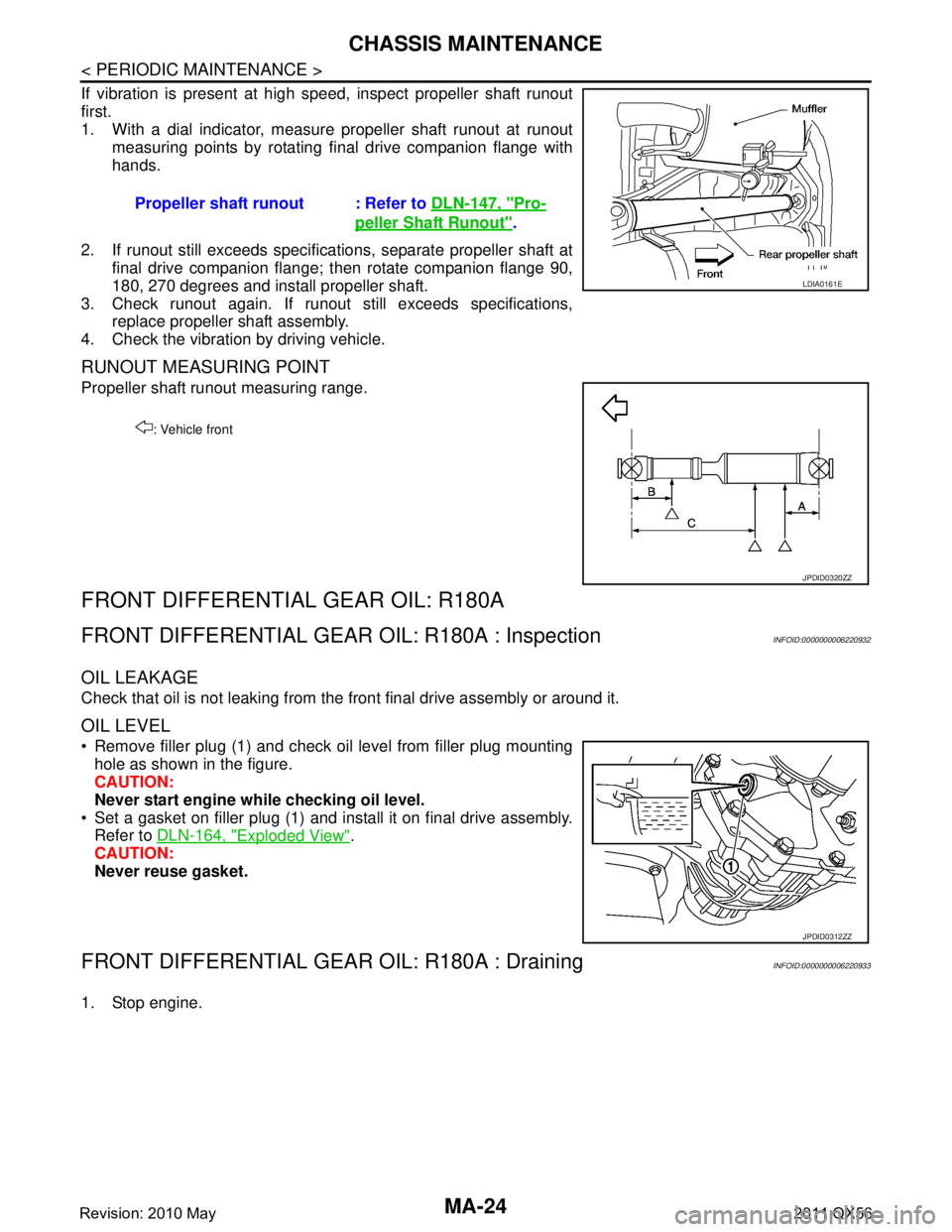
If vibration is present at high speed, inspect propeller shaft runout
first.
1. With a dial indicator, measure propeller shaft runout at runoutmeasuring points by rotating final drive companion flange with
hands.
2. If runout still exceeds specifications, separate propeller shaft at final drive companion flange; then rotate companion flange 90,
180, 270 degrees and install propeller shaft.
3. Check runout again. If runout still exceeds specifications, replace propeller shaft assembly.
4. Check the vibration by driving vehicle.
RUNOUT MEASURING POINT
Propeller shaft runout measuring range.
FRONT DIFFERENTIAL GEAR OIL: R180A
FRONT DIFFERENTIAL GEAR OIL: R180A : InspectionINFOID:0000000006220932
OIL LEAKAGE
Check that oil is not leaking from the front final drive assembly or around it.
OIL LEVEL
Remove filler plug (1) and check oil level from filler plug mounting
hole as shown in the figure.
CAUTION:
Never start engine while checking oil level.
Set a gasket on filler plug (1) and install it on final drive assembly. Refer to DLN-164, "
Exploded View".
CAUTION:
Never reuse gasket.
FRONT DIFFERENTIAL GEAR OIL: R180A : DrainingINFOID:0000000006220933
1. Stop engine.Propeller shaft runout : Refer to
DLN-147, "
Pro-
peller Shaft Runout".
LDIA0161E
: Vehicle front
JPDID0320ZZ
JPDID0312ZZ
Revision: 2010 May2011 QX56
Page 3695 of 5598
CHASSIS MAINTENANCEMA-25
< PERIODIC MAINTENANCE >
C
DE
F
G H
I
J
K L
M B
MA
N
O A
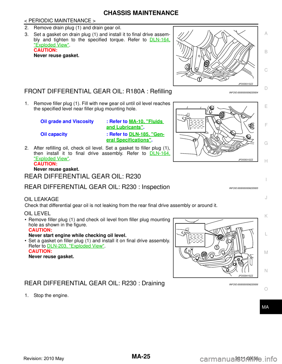
2. Remove drain plug (1) and drain gear oil.
3. Set a gasket on drain plug (1) and install it to final drive assem-
bly and tighten to the specified torque. Refer to DLN-164,
"Exploded View".
CAUTION:
Never reuse gasket.
FRONT DIFFERENTIAL GEAR OIL: R180A : RefillingINFOID:0000000006220934
1. Remove filler plug (1). Fill with new gear oil until oil level reaches
the specified level near filler plug mounting hole.
2. After refilling oil, check oil level. Set a gasket to filler plug (1), then install it to final drive assembly. Refer to DLN-164,
"Exploded View".
CAUTION:
Never reuse gasket.
REAR DIFFERENTIAL GEAR OIL: R230
REAR DIFFERENTIAL GEAR OIL: R230 : InspectionINFOID:0000000006220935
OIL LEAKAGE
Check that differential gear oil is not leaking fr om the rear final drive assembly or around it.
OIL LEVEL
Remove filler plug (1) and check oil level from filler plug mounting
hole as shown in the figure.
CAUTION:
Never start engine while checking oil level.
Set a gasket on filler plug (1) and install it on final drive assembly. Refer to DLN-203, "
Exploded View".
CAUTION:
Never reuse gasket.
REAR DIFFERENTIAL GEAR OIL: R230 : DrainingINFOID:0000000006220936
1. Stop the engine.
JPDID0313ZZ
Oil grade and Viscosity : Refer to MA-10, "Fluids
and Lubricants".
Oil capacity : Refer to DLN-185, "
Gen-
eral Specifications".
JPDID0312ZZ
JPDID0415ZZ
Revision: 2010 May2011 QX56
Page 3731 of 5598
MIR-26
< SYMPTOM DIAGNOSIS >
SQUEAK AND RATTLE TROUBLE DIAGNOSES
Insulates where slight movement is present. Ideal for instrument panel applications.
SILICONE GREASE
Used in place of UHMW tape that will be visible or not fit. Will only last a few months.
SILICONE SPRAY
Use when grease cannot be applied.
DUCT TAPE
Use to eliminate movement.
CONFIRM THE REPAIR
Confirm that the cause of a noise is repaired by test driving the vehicle. Operate the vehicle under the same
conditions as when the noise originally occurred. Refer to the notes on the Diagnostic Worksheet.
Inspection ProcedureINFOID:0000000006257248
Refer to Table of Contents for specific component removal and installationinformation.
INSTRUMENT PANEL
Most incidents are caused by contact and movement between:
1. The cluster lid A and instrument panel
2. Acrylic lens and combination meter housing
3. Instrument panel to front pillar garnish
4. Instrument panel to windshield
5. Instrument panel mounting pins
6. Wiring harnesses behind the combination meter
7. A/C defroster duct and duct joint
These incidents can usually be located by tapping or moving the components to duplicate the noise or by
pressing on the components while driving to stop the noise. Most of these incidents can be repaired by
applying felt cloth tape or silicon spray (in hard to reach areas). Urethane pads can be used to insulate
wiring harness.
CAUTION:
Do not use silicone spray to is olate a squeak or rattle. If you saturatethe area with silicone, you
will not be able to recheck the repair.
CENTER CONSOLE
Components to pay attention to include:
1. Shifter assembly cover to finisher
2. A/C control unit and cluster lid C
3. Wiring harnesses behind audio and A/C control unit
The instrument panel repair and isolation pr ocedures also apply to thecenter console.
DOORS
Pay attention to the:
1. Finisher and inner panel making a slapping noise
2. Inside handle escutcheon to door finisher
3. Wiring harnesses tapping
4. Door striker out of alignment causing a popping noise on startsand stops
Tapping or moving the components or pressing on them wh ile driving to duplicate the conditions can isolate
many of these incidents. You can usually insulate the areas with felt cloth tape or insulator foam blocks from
the Nissan Squeak and Rattle Kit (J-43980) to repair the noise.
TRUNK
Trunk noises are often caused by a loose jack or loose items put intothe trunk by the owner.
In addition look for:
1. Trunk lid dumpers out of adjustment
2. Trunk lid striker out of adjustment
3. The trunk lid torsion bars knocking together
4. A loose license plate or bracket
Revision: 2010 May2011 QX56