Page 1771 of 5598
BACK DOORDLK-235
< REMOVAL AND INSTALLATION >
C
DE
F
G H
I
J
L
M A
B
DLK
N
O P
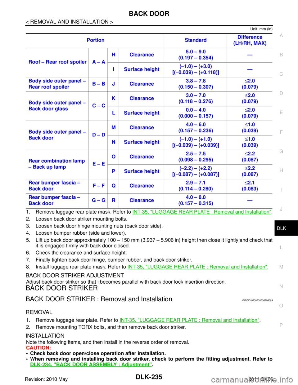
Unit: mm (in)
1. Remove luggage rear plate mask. Refer to INT-35, "LUGGAGE REAR PLATE : Removal and Installation".
2. Loosen back door striker mounting bolts.
3. Loosen back door hinge mounting nuts (back door side).
4. Loosen bumper rubber (side and lower).
5. Lift up back door approximately 100 – 150 mm (3.937 – 5.906 in) height then close it lightly and check that
it is engaged firmly with back door closed.
6. Check the clearance and surface height.
7. Finally tighten back door hinge, bumper rubber, and back door striker.
8. Install luggage rear plate mask. Refer to INT-35, "
LUGGAGE REAR PLATE : Removal and Installation".
BACK DOOR STRIKER ADJUSTMENT
Adjust back door striker so that i becomes parallel with back door lock insertion direction.
BACK DOOR STRIKER
BACK DOOR STRIKER : Removal and InstallationINFOID:0000000006226089
REMOVAL
1. Remove luggage rear plate. Refer to INT-35, "LUGGAGE REAR PLATE : Removal and Installation".
2. Remove mounting TORX bolts, and then remove back door striker.
INSTALLATION
Note the following items, and then install in the reverse order of removal.
CAUTION:
Check back door open/close ope ration after installation.
When removing and installing b ack door striker, check to perform th e fitting adjustment. Refer to
DLK-234, "
BACK DOOR ASSEMBLY : Adjustment".
Portion Standard
Difference
(LH/RH, MAX)
Roof – Rear roof spoiler A – A H Clearance
5.0 – 9.0
(0.197 – 0.354) —
I Surface height (
− 1.0) – (+3.0)
[( −0.039) – (+0.118)] —
Body side outer panel –
Rear roof spoiler B – B J Clearance 3.8 – 7.8
(0.150 – 0.307) ≤
2.0
(0.079)
Body side outer panel –
Back door glass C – CK Clearance
3.0 – 7.0
(0.118 – 0.276) ≤
2.0
(0.079)
L Surface height 0.0 – 4.0
(0.000 – 0.157) ≤
2.0
(0.079)
Body side outer panel –
Back door D – DM Clearance
4.0 – 6.0
(0.157 – 0.236) ≤
1.0
(0.039)
N Surface height (
− 1.0) – (+1.0)
[( −0.039) – (+0.039)] ≤
1.0
(0.039)
Rear combination lamp
– Back up lamp E – EO Clearance
2.5 – 7.5
(0.098 – 0.295) ≤
2.2
(0.087)
P Surface height (
− 2.2) – (+2.2)
[( −0.087) – (+0.087)] ≤
2.2
(0.087)
Rear bumper fascia –
Back door F – F Q Clearance 2.9 – 7.1
(0.114 – 0.280) ≤
2.1
(0.083)
Rear bumper fascia –
Back door G – G R Clearance 4.0 – 8.0
(0.157 – 0.315) —
Revision: 2010 May2011 QX56
Page 1772 of 5598
DLK-236
< REMOVAL AND INSTALLATION >
BACK DOOR
BACK DOOR HINGE
BACK DOOR HINGE : Removal and InstallationINFOID:0000000006226090
CAUTION:
Operate with two workers, because of its heavy weight.
Use protective tape or cloth to protect fr om damage during remove and installation.
REMOVAL
1. Remove back door assembly. Refer to DLK-232, "BACK DOOR ASSEMBLY : Removal and Installation".
2. Remove back door hinge mounting nuts (body side), and then remove back door hinge.
INSTALLATION
Note the following items, and then install in the reverse order of removal.
CAUTION:
Apply anticorrosive agent onto the mounting surface.
Check back door open/close op eration after installation.
Check back door hinge ro tating part for poor lubricatio n. If necessary, apply body grease.
When removing and installing back door assembly, perform the fitting adjustment. Refer to DLK-234,
"BACK DOOR ASSEMBLY : Adjustment".
After installation, apply touch-up paint (the body color) onto the head of back door hinge mounting
nuts.
BACK DOOR STAY
BACK DOOR STAY : Removal and InstallationINFOID:0000000006226091
REMOVAL
1. Support back door lock with the proper material to prevent it from falling.
WARNING:
Body injury may occur if no su pporting rod is holding the back door op en when removing the
back door stay.
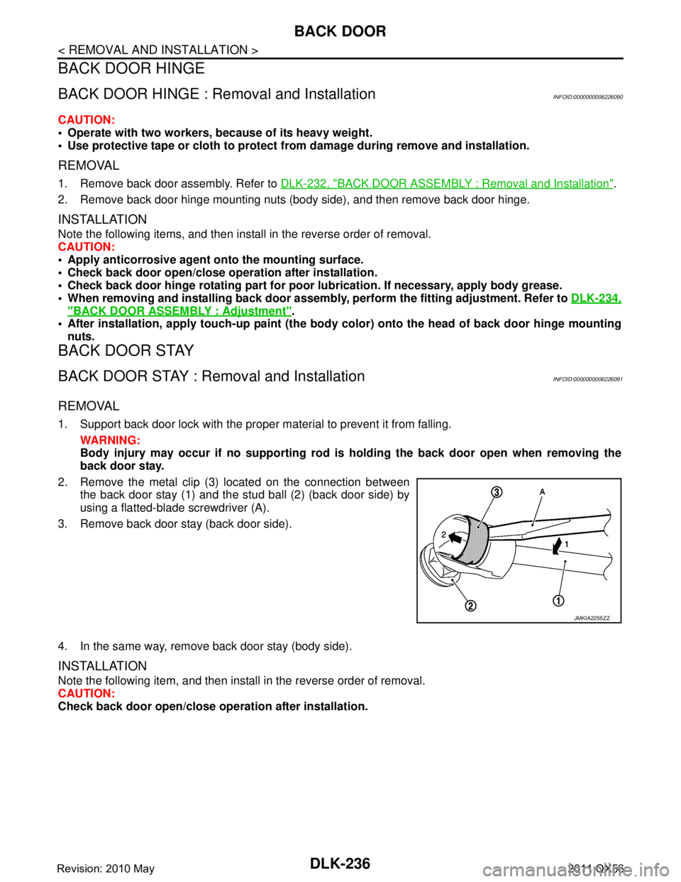
2. Remove the metal clip (3) located on the connection between the back door stay (1) and the stud ball (2) (back door side) by
using a flatted-blade screwdriver (A).
3. Remove back door stay (back door side).
4. In the same way, remove back door stay (body side).
INSTALLATION
Note the following item, and then install in the reverse order of removal.
CAUTION:
Check back door open/close ope ration after installation.
JMKIA2255ZZ
Revision: 2010 May2011 QX56
Page 1776 of 5598
DLK-240
< REMOVAL AND INSTALLATION >
FRONT DOOR LOCK
FRONT DOOR LOCK
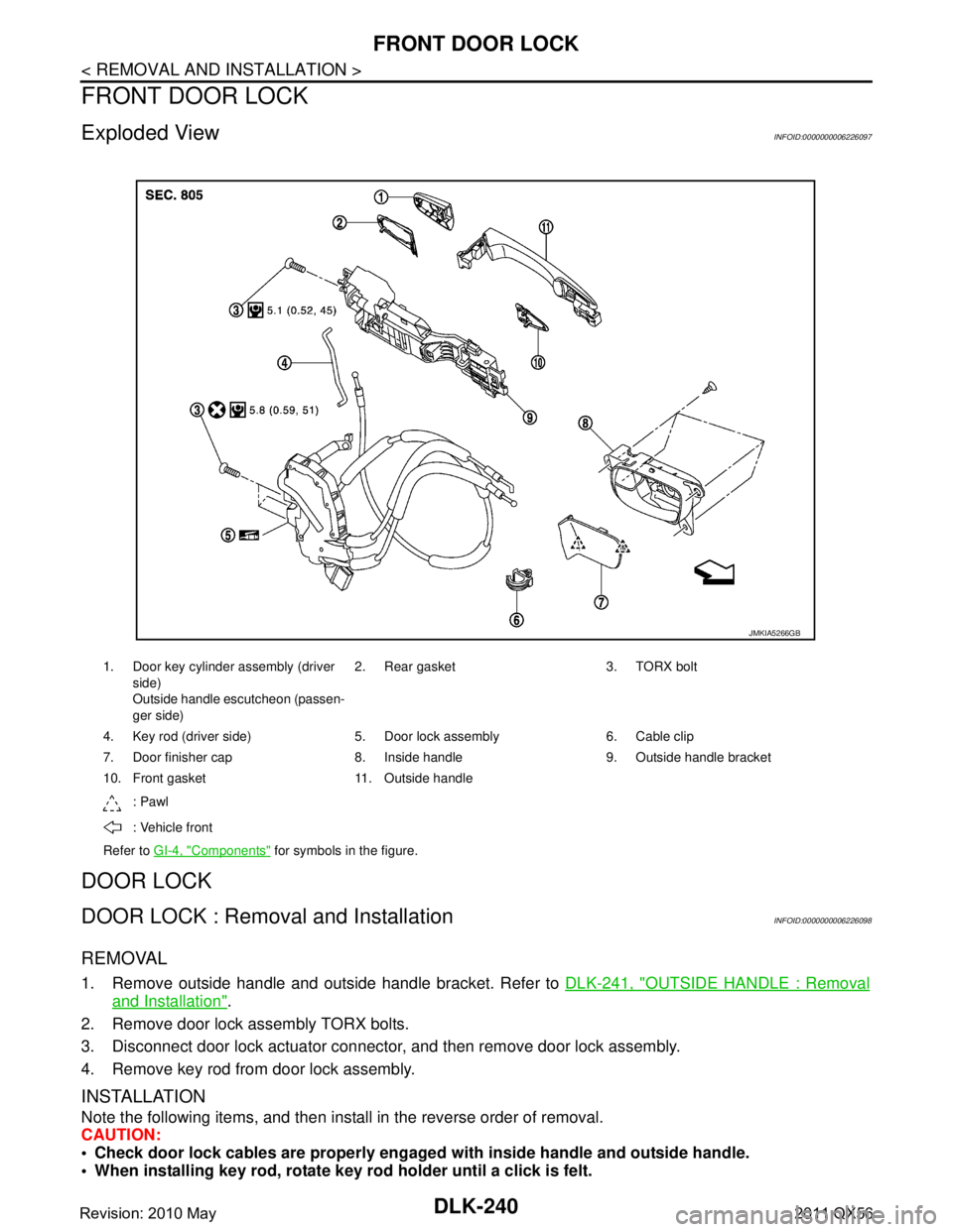
Exploded ViewINFOID:0000000006226097
DOOR LOCK
DOOR LOCK : Removal and InstallationINFOID:0000000006226098
REMOVAL
1. Remove outside handle and outside handle bracket. Refer to DLK-241, "OUTSIDE HANDLE : Removal
and Installation".
2. Remove door lock assembly TORX bolts.
3. Disconnect door lock actuator connector, and then remove door lock assembly.
4. Remove key rod from door lock assembly.
INSTALLATION
Note the following items, and then install in the reverse order of removal.
CAUTION:
Check door lock cables are properly engage d with inside handle and outside handle.
When installing key rod, rotate key rod holder until a click is felt.
1. Door key cylinder assembly (driver
side)
Outside handle escutcheon (passen-
ger side) 2. Rear gasket 3. TORX bolt
4. Key rod (driver si de) 5. Door lock assembly 6. Cable clip
7. Door finisher cap 8. Inside handle 9. Outside handle bracket
10. Front gasket 11. Outside handle
: Pawl
: Vehicle front
Refer to GI-4, "
Components" for symbols in the figure.
JMKIA5266GB
Revision: 2010 May2011 QX56
Page 1777 of 5598
FRONT DOOR LOCKDLK-241
< REMOVAL AND INSTALLATION >
C
DE
F
G H
I
J
L
M A
B
DLK
N
O P
After installation, check door open/close, lock/unlock operation.
INSIDE HANDLE
INSIDE HANDLE : Removal and InstallationINFOID:0000000006226099
REMOVAL
1. Remove front door finisher. Refer to INT-14, "Removal and Installation".
2. Remove inside handle escutcheon. Refer to INT-13, "
Exploded View".
3. Remove inside handle mounting screws, and then remove the inside handle.
INSTALLATION
Note the following items, and then install in the reverse order of removal.
CAUTION:
Check door lock cables are properly engaged with inside handle.
After installation, check door open/close, lock/unlock operation.
OUTSIDE HANDLE
OUTSIDE HANDLE : Removal and InstallationINFOID:0000000006226100
REMOVAL
1. Fully close front door glass.
2. Remove front door finisher. Refer to INT-14, "
Removal and Installation".
3. Remove sealing screen. NOTE:
Cat the buty-tape so that some parts of the buty-t ape do not remain on the sealing screen, if the sealing
screen is reused.
4. Disconnect door antenna and door request switch c onnector, and then remove harness clamp (models
with Intelligent Key system) on outside handle bracket.
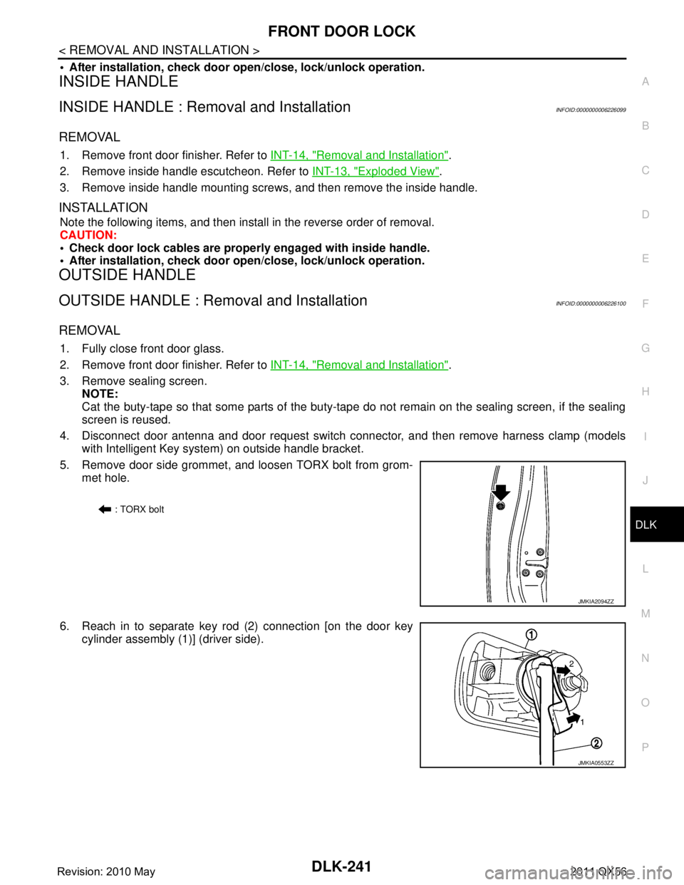
5. Remove door side grommet, and loosen TORX bolt from grom-
met hole.
6. Reach in to separate key rod (2) connection [on the door key cylinder assembly (1)] (driver side).
: TORX bolt
JMKIA2094ZZ
JMKIA0553ZZ
Revision: 2010 May2011 QX56
Page 1778 of 5598
DLK-242
< REMOVAL AND INSTALLATION >
FRONT DOOR LOCK
7. While pulling outside handle, remove door key cylinder assem-bly (driver side) or outside handle escutcheon (passenger side).
8. While pulling outside handle (1), slide toward rear of vehicle to remove outside handle.
9. Remove front gasket and rear gasket.
10. Slide toward rear of vehicle to remove outside handle bracket.
11. Disconnect door lock cable from outside handle bracket.
INSTALLATION
Note the following items, and then install in the reverse order of removal.
CAUTION:
When installing key rod, rotate key rod holder until a click is felt.
Check door lock cable is properly engaged with outside handle bracket.
After installation, check door op en/close, lock/unlock operation.
JMKIA0560ZZ
JMKIA0524ZZ
JMKIA2652ZZ
Revision: 2010 May2011 QX56
Page 1779 of 5598
REAR DOOR LOCKDLK-243
< REMOVAL AND INSTALLATION >
C
DE
F
G H
I
J
L
M A
B
DLK
N
O P
REAR DOOR LOCK
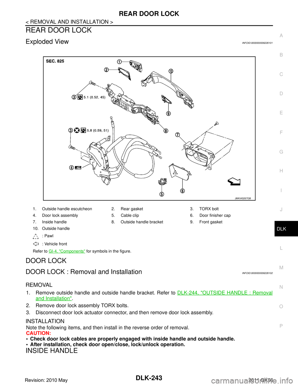
Exploded ViewINFOID:0000000006226101
DOOR LOCK
DOOR LOCK : Remova l and InstallationINFOID:0000000006226102
REMOVAL
1. Remove outside handle and outside handle bracket. Refer to DLK-244, "OUTSIDE HANDLE : Removal
and Installation".
2. Remove door lock assembly TORX bolts.
3. Disconnect door lock actuator connector, and then remove door lock assembly.
INSTALLATION
Note the following items, and then install in the reverse order of removal.
CAUTION:
Check door lock cables are properly engage d with inside handle and outside handle.
After installation, check door op en/close, lock/unlock operation.
INSIDE HANDLE
1. Outside handle escutcheon 2. Rear gasket 3. TORX bolt
4. Door lock assembly 5. Cable clip 6. Door finisher cap
7. Inside handle 8. Outside handle bracket 9. Front gasket
10. Outside handle
: Pawl
: Vehicle front
Refer to GI-4, "
Components" for symbols in the figure.
JMKIA5267GB
Revision: 2010 May2011 QX56
Page 1780 of 5598
DLK-244
< REMOVAL AND INSTALLATION >
REAR DOOR LOCK
INSIDE HANDLE : Removal and Installation
INFOID:0000000006226103
REMOVAL
1. Remove rear door finisher. Refer to INT-16, "Removal and Installation".
2. Remove inside handle escutcheon. Refer to INT-16, "
Exploded View"
3. Remove inside handle mounting screws, and then remove inside handle.
INSTALLATION
Note the following items, and then install in the reverse order of removal.
CAUTION:
Check door lock cables are properly engaged with inside handle.
After installation, check door open/close, lock/unlock operation.
OUTSIDE HANDLE
OUTSIDE HANDLE : Removal and InstallationINFOID:0000000006226104
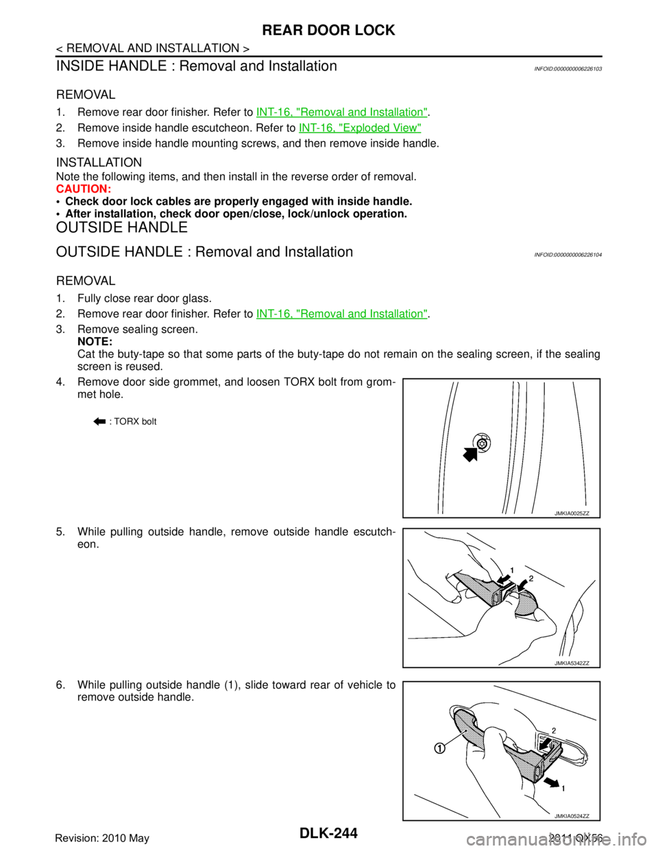
REMOVAL
1. Fully close rear door glass.
2. Remove rear door finisher. Refer to INT-16, "
Removal and Installation".
3. Remove sealing screen. NOTE:
Cat the buty-tape so that some parts of the buty-t ape do not remain on the sealing screen, if the sealing
screen is reused.
4. Remove door side grommet, and loosen TORX bolt from grom- met hole.
5. While pulling outside handle, remove outside handle escutch- eon.
6. While pulling outside handle (1), slide toward rear of vehicle to remove outside handle.
: TORX bolt
JMKIA0025ZZ
JMKIA5342ZZ
JMKIA0524ZZ
Revision: 2010 May2011 QX56
Page 1781 of 5598
REAR DOOR LOCKDLK-245
< REMOVAL AND INSTALLATION >
C
DE
F
G H
I
J
L
M A
B
DLK
N
O P
7. Remove front gasket and rear gasket.
8. Slide toward rear of vehicle to remove outside handle bracket.
9. Disconnect door lock cable from outside handle bracket.
INSTALLATION
Note the following items, and then install in the reverse order of removal.
CAUTION:
Check door lock cable is properly engaged with outside handle bracket.
After installation, check door op en/close, lock/unlock operation.
JMKIA2652ZZ
Revision: 2010 May2011 QX56