2011 INFINITI QX56 door lock
[x] Cancel search: door lockPage 1669 of 5598

DOOR KEY CYLINDER SWITCHDLK-133
< DTC/CIRCUIT DIAGNOSIS >
C
DE
F
G H
I
J
L
M A
B
DLK
N
O P
NO >> Repair or replace harness.
3.CHECK DOOR KEY CYLINDER SWITCH GROUND CIRCUIT
Check continuity between front door lock assembly (driver side) harness connector and ground.
Is the inspection result normal?
YES >> GO TO 4.
NO >> Repair or replace harness.
4.CHECK DOOR KEY CYLINDER SWITCH
Refer to DLK-133, "
Component Inspection".
Is the inspection result normal?
YES >> GO TO 5.
NO >> Replace front door lock assembly (driver side).
5.CHECK INTERMITTENT INCIDENT
Refer to GI-40, "
Intermittent Incident".
>> INSPECTION END
Component InspectionINFOID:0000000006225946
1.CHECK DOOR KEY CYLINDER SWITCH
1. Turn ignition switch OFF.
2. Disconnect front door lock assembly (driver side) connector.
3. Check continuity between front door lock assembly (driver side) terminals.
Is the inspection result normal?
YES >> INSPECTION END
NO >> Replace front door lock assembly (driver side).
Front door lock assembly (driver side)
GroundContinuity
Connector Terminal
D9 4 Existed
Front door lock assembly (driver side) Condition Continuity
Te r m i n a l
5 4 Driver side door key cylinder Unlock Existed
Neutral / Lock Not existed
6 Lock Existed
Neutral / Unlock Not existed
Revision: 2010 May2011 QX56
Page 1692 of 5598

DLK-156
< DTC/CIRCUIT DIAGNOSIS >
HALF LATCH SWITCH
HALF LATCH SWITCH
Component Function CheckINFOID:0000000006225980
1.CHECK FUNCTION
1. Select “AUTOMATIC BACK DOOR CONTROL UNIT” using CONSULT-III.
2. Select “HALF LATCH SW” in “DATA MONITOR” mode.
3. Check that the function operates normall y according to the following conditions.
Is the inspection result normal?
YES >> Half latch switch is OK.
NO >> Refer to DLK-156, "
Diagnosis Procedure".
Diagnosis ProcedureINFOID:0000000006225981
1.CHECK HALF LATCH SWITCH INPUT SIGNAL
1. Turn ignition switch OFF.
2. Disconnect back door lock assembly connector.
3. Check voltage between back door lock assembly harness connector and ground.
Is the inspection result normal?
YES >> GO TO 3.
NO >> GO TO 2.
2.CHECK HALF LATCH SWITCH CIRCUIT
1. Disconnect automatic back door control module connector.
2. Check continuity between automatic back door control module harness connector.
3. Check continuity between automatic back door control module harness connector and ground.
Is the inspection result normal?
YES >> Replace automatic back door control module. Refer to DLK-262, "Removal and Installation".
NO >> Repair or replace harness.
3.CHECK HALF LATCH SWITCH GROUND CIRCUIT
Check continuity between back door lock assembly harness connector and ground.
Monitor item Condition Status
HALF LATCH SW Back door Fully closed/Half latch OFF
Open ON
(–)
(–)Voltag e
(Approx.)
Back door lock assembly
Connector Terminal D157 6 Ground Battery voltage
Automatic back door control module Back door lock assembly Continuity
Connector Terminal Connector Terminal
B26 8 D157 6 Existed
Automatic back door control module GroundContinuity
Connector Terminal
B26 8 Not existed
Back door lock assembly GroundContinuity
Connector Terminal
D157 8 Existed
Revision: 2010 May2011 QX56
Page 1693 of 5598

HALF LATCH SWITCHDLK-157
< DTC/CIRCUIT DIAGNOSIS >
C
DE
F
G H
I
J
L
M A
B
DLK
N
O P
Is the inspection result normal?
YES >> GO TO 4.
NO >> Repair or replace harness.
4.CHECK HALF LATCH SWITCH
Refer to DLK-157, "
Component Inspection".
Is the inspection result normal?
YES >> GO TO 5.
NO >> Replace back door lock assembly.
5.CHECK INTERMITTENT INCIDENT
Refer to GI-40, "
Intermittent Incident".
>> INSPECTION END
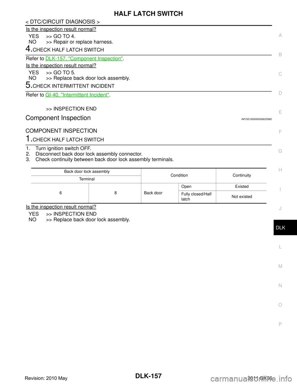
Component InspectionINFOID:0000000006225982
COMPONENT INSPECTION
1.CHECK HALF LATCH SWITCH
1. Turn ignition switch OFF.
2. Disconnect back door lock assembly connector.
3. Check continuity between back door lock assembly terminals.
Is the inspection result normal?
YES >> INSPECTION END
NO >> Replace back door lock assembly.
Back door lock assembly Condition Continuity
Te r m i n a l
6 8 Back door Open Existed
Fully closed/Half
latch
Not existed
Revision: 2010 May2011 QX56
Page 1698 of 5598

DLK-162
< DTC/CIRCUIT DIAGNOSIS >
BACK DOOR CLOSURE MOTOR
BACK DOOR CLOSURE MOTOR
Diagnosis ProcedureINFOID:0000000006225989
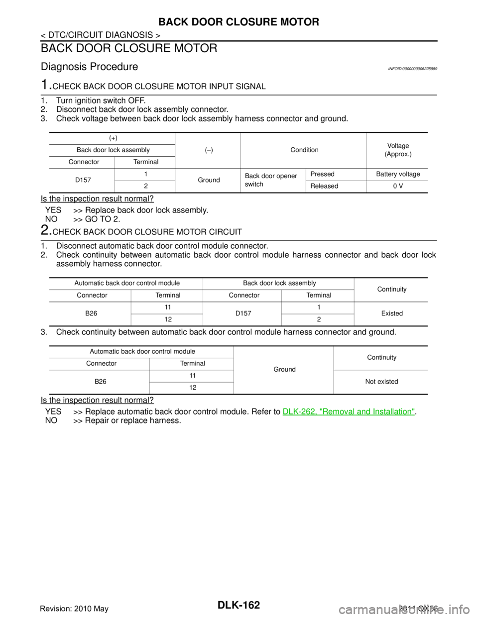
1.CHECK BACK DOOR CLOSURE MOTOR INPUT SIGNAL
1. Turn ignition switch OFF.
2. Disconnect back door lock assembly connector.
3. Check voltage between back door lock assembly harness connector and ground.
Is the inspection result normal?
YES >> Replace back door lock assembly.
NO >> GO TO 2.
2.CHECK BACK DOOR CLOSURE MOTOR CIRCUIT
1. Disconnect automatic back door control module connector.
2. Check continuity between automatic back door control module harness connector and back door lock
assembly harness connector.
3. Check continuity between automatic back door control module harness connector and ground.
Is the inspection result normal?
YES >> Replace automatic back door control module. Refer to DLK-262, "Removal and Installation".
NO >> Repair or replace harness.
(+)
(–) Condition Voltag e
(Approx.)
Back door lock assembly
Connector Terminal
D157 1
GroundBack door opener
switch Pressed Battery voltage
2Released0 V
Automatic back door control module Back door lock assembly Continuity
Connector Terminal Connector Terminal
B26 11
D157 1
Existed
12 2
Automatic back door control module GroundContinuity
Connector Terminal
B26 11
Not existed
12
Revision: 2010 May2011 QX56
Page 1699 of 5598

AUTOMATIC BACK DOOR WARNING BUZZERDLK-163
< DTC/CIRCUIT DIAGNOSIS >
C
DE
F
G H
I
J
L
M A
B
DLK
N
O P
AUTOMATIC BACK DOOR WARNING BUZZER
Diagnosis ProcedureINFOID:0000000006225990
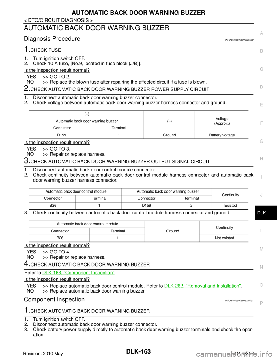
1.CHECK FUSE
1. Turn ignition switch OFF.
2. Check 10 A fuse, [No.9, located in fuse block (J/B)].
Is the inspection result normal?
YES >> GO TO 2.
NO >> Replace the blown fuse after repairing the affected circuit if a fuse is blown.
2.CHECK AUTOMATIC BACK DOOR WARNI NG BUZZER POWER SUPPLY CIRCUIT
1. Disconnect automatic back door warning buzzer connector.
2. Check voltage between automatic back door warning buzzer harness connector and ground.
Is the inspection result normal?
YES >> GO TO 3.
NO >> Repair or replace harness.
3.CHECK AUTOMATIC BACK DOOR WARNING BUZZER OUTPUT SIGNAL CIRCUIT
1. Disconnect automatic back door control module connector.
2. Check continuity between automatic back door control module harness connector and automatic back
door warning buzzer harness connector.
3. Check continuity between automatic back door control module harness connector and ground.
Is the inspection result normal?
YES >> GO TO 4.
NO >> Repair or replace harness.
4.CHECK AUTOMATIC BACK DOOR WARNING BUZZER
Refer to DLK-163, "
Component Inspection"
Is the inspection result normal?
YES >> Replace automatic back door control module. Refer to DLK-262, "Removal and Installation".
NO >> Replace automatic back door warning buzzer.
Component InspectionINFOID:0000000006225991
1.CHECK AUTOMATIC BACK DOOR WARNING BUZZER
1. Turn ignition switch OFF.
2. Disconnect automatic back door warning buzzer connector.
3. Check battery power supply directly to automatic back door warning buzzer terminals and check the oper-
ation.
(+)
(–)Voltag e
(Approx.)
Automatic back door warning buzzer
Connector Terminal D159 1 Ground Battery voltage
Automatic back door control module Automatic back door warning buzzer Continuity
Connector Terminal Connector Terminal
B26 1 D159 2 Existed
Automatic back door control module GroundContinuity
Connector Terminal
B26 1 Not existed
Revision: 2010 May2011 QX56
Page 1702 of 5598

DLK-166
< DTC/CIRCUIT DIAGNOSIS >
INTEGRATED HOMELINK TRANSMITTER
INTEGRATED HOMELINK TRANSMITTER
Component Function CheckINFOID:0000000006256149
1.CHECK FUNCTION
Check that system receiver (garage door opener, et c.) operates with original hand-held transmitter.
Is the inspection result normal?
YES >> GO TO 2.
NO >> Receiver or hand-held transmitter is malfunctioning.
2.CHECK ILLUMINATE
1. Turn ignition switch OFF.
2. Does red light of transmitter illuminat e when any transmitter button is pressed?
Is the inspection result normal?
YES >> GO TO 3.
NO >> Refer to DLK-166, "
Diagnosis Procedure".
3.CHECK TRANSMITTER
Check transmitter with Tool*.
*:For details, refer to Technical Service Bulletin.
Is the inspection result normal?
YES >> Receiver or hand-held transmitter malfunction, not vehicle related.
NO >> Replace auto anti-dazzling inside mirror (integrated homelink transmitter).
Diagnosis ProcedureINFOID:0000000006256150
1.CHECK POWER SUPPLY
1. Turn ignition switch OFF.
2. Disconnect auto anti-dazzling inside mirror (integrated homelink transmitter) connector.
3. Check voltage between auto anti-dazzling inside mirro r (integrated homelink transmitter) harness connec-
tor and ground.
Is the inspection result normal?
YES >> GO TO 2.
NO-1 >> Check 10 A fuse [No. 6 located in the fuse block (J/B)].
NO-2 >> Harness for open or short between fuse and aut o anti-dazzling inside mirror (integrated homelink
transmitter).
2.CHECK GROUND CIRCUIT
Check continuity between auto anti-dazzling inside mi rror (integrated homelink transmitter) harness connector
and ground.
Is the inspection result normal?
YES >> GO TO 3.
NO >> Repair or replace harness.
(+)
(–)Vo l ta g e
(Approx.)
Auto anti-dazzling inside mirror
(Integrated homelink transmitter)
Connector Terminal
R25 6
Ground Battery voltage
10
Auto anti-dazzling inside mirror
(Integrated homelink transmitter) GroundContinuity
Connector Terminal
R25 8 Existed
Revision: 2010 May2011 QX56
Page 1704 of 5598

DLK-168
< SYMPTOM DIAGNOSIS >
DOOR DOES NOT LOCK/UNLOCK WITH DOOR LOCK AND UNLOCK SWITCH
SYMPTOM DIAGNOSIS
DOOR DOES NOT LOCK/UNLOCK WITH DOOR LOCK AND UNLOCK
SWITCH
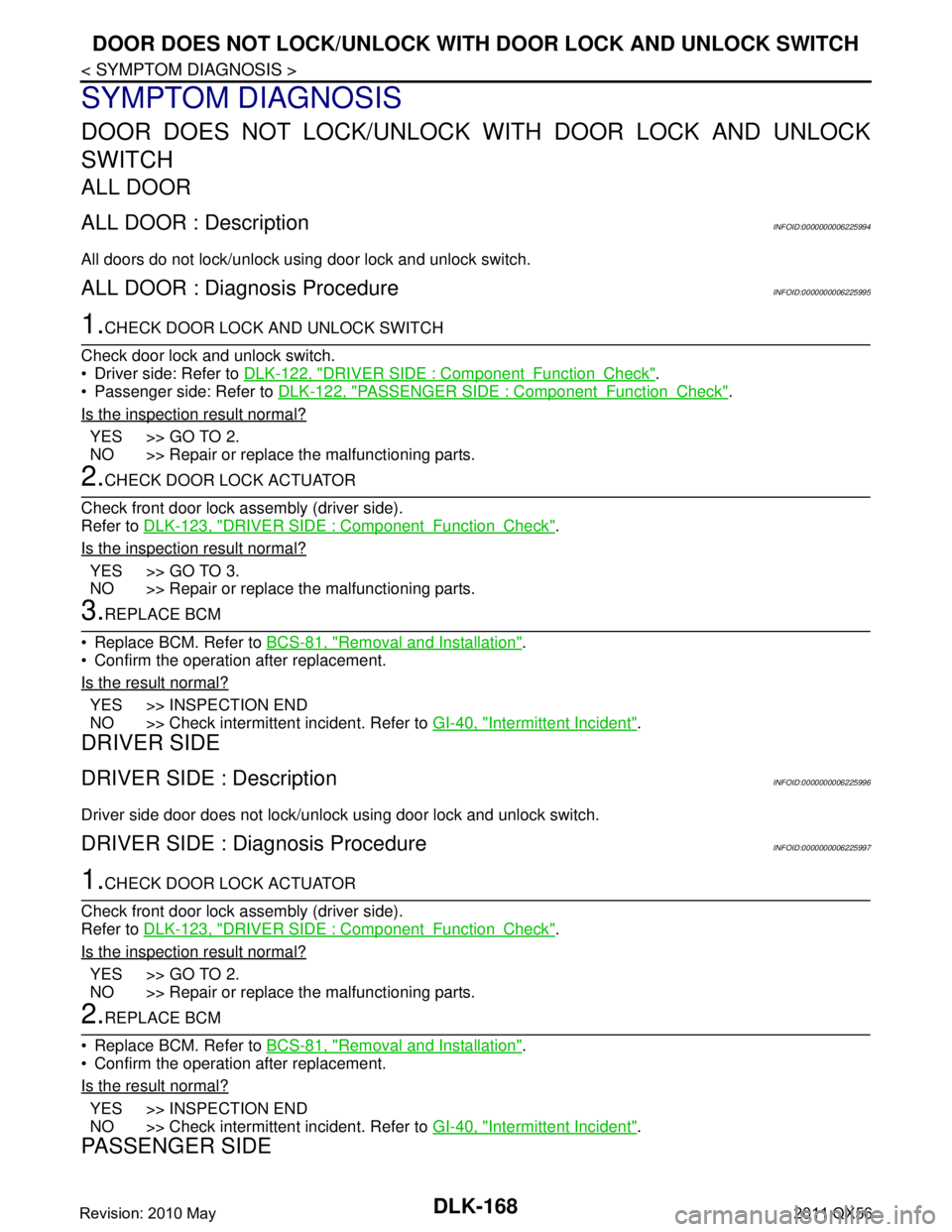
ALL DOOR
ALL DOOR : DescriptionINFOID:0000000006225994
All doors do not lock/unlock using door lock and unlock switch.
ALL DOOR : Diagnosis ProcedureINFOID:0000000006225995
1.CHECK DOOR LOCK AND UNLOCK SWITCH
Check door lock and unlock switch.
Driver side: Refer to DLK-122, "
DRIVER SIDE : ComponentFunctionCheck".
Passenger side: Refer to DLK-122, "
PASSENGER SIDE : ComponentFunctionCheck".
Is the inspection result normal?
YES >> GO TO 2.
NO >> Repair or replace the malfunctioning parts.
2.CHECK DOOR LOCK ACTUATOR
Check front door lock assembly (driver side).
Refer to DLK-123, "
DRIVER SIDE : ComponentFunctionCheck".
Is the inspection result normal?
YES >> GO TO 3.
NO >> Repair or replace the malfunctioning parts.
3.REPLACE BCM
Replace BCM. Refer to BCS-81, "
Removal and Installation".
Confirm the operation after replacement.
Is the result normal?
YES >> INSPECTION END
NO >> Check intermittent incident. Refer to GI-40, "
Intermittent Incident".
DRIVER SIDE
DRIVER SIDE : DescriptionINFOID:0000000006225996
Driver side door does not lock/unlock using door lock and unlock switch.
DRIVER SIDE : Diagnosis ProcedureINFOID:0000000006225997
1.CHECK DOOR LOCK ACTUATOR
Check front door lock assembly (driver side).
Refer to DLK-123, "
DRIVER SIDE : ComponentFunctionCheck".
Is the inspection result normal?
YES >> GO TO 2.
NO >> Repair or replace the malfunctioning parts.
2.REPLACE BCM
Replace BCM. Refer to BCS-81, "
Removal and Installation".
Confirm the operation after replacement.
Is the result normal?
YES >> INSPECTION END
NO >> Check intermittent incident. Refer to GI-40, "
Intermittent Incident".
PASSENGER SIDE
Revision: 2010 May2011 QX56
Page 1705 of 5598

DOOR DOES NOT LOCK/UNLOCK WITH DOOR LOCK AND UNLOCK SWITCH
DLK-169
< SYMPTOM DIAGNOSIS >
C
D E
F
G H
I
J
L
M A
B
DLK
N
O P
PASSENGER SIDE : DescriptionINFOID:0000000006225998
Passenger side door does not lock/unloc k using door lock and unlock switch.
PASSENGER SIDE : Diagnosis ProcedureINFOID:0000000006225999
1.CHECK DOOR LOCK ACTUATOR
Check front door lock assembly (passenger side).
Refer to DLK-124, "
PASSENGER SIDE : ComponentFunctionCheck".
Is the inspection result normal?
YES >> GO TO 2.
NO >> Repair or replace the malfunctioning parts.
2.REPLACE BCM
Replace BCM. Refer to BCS-81, "
Removal and Installation".
Confirm the operation after replacement.
Is the result normal?
YES >> INSPECTION END
NO >> Check intermittent incident. Refer to GI-40, "
Intermittent Incident".
REAR LH
REAR LH : DescriptionINFOID:0000000006226000
Rear LH side door does not lock/unlock using door lock and unlock switch.
REAR LH : Diagnosis ProcedureINFOID:0000000006226001
1.CHECK DOOR LOCK ACTUATOR
Check rear door lock assembly LH.
Refer to DLK-125, "
REAR LH : ComponentFunctionCheck".
Is the inspection result normal?
YES >> GO TO 2.
NO >> Repair or replace the malfunctioning parts.
2.REPLACE BCM
Replace BCM. Refer to BCS-81, "
Removal and Installation".
Confirm the operation after replacement.
Is the result normal?
YES >> INSPECTION END
NO >> Check intermittent incident. Refer to GI-40, "
Intermittent Incident".
REAR RH
REAR RH : DescriptionINFOID:0000000006226002
Rear RH side door does not lock/unlock using door lock and unlock switch.
REAR RH : Diagnosis ProcedureINFOID:0000000006226003
1.CHECK DOOR LOCK ACTUATOR
Check rear door lock assembly RH.
Refer to DLK-126, "
REAR RH : ComponentFunctionCheck".
Is the inspection result normal?
YES >> GO TO 2.
NO >> Repair or replace the malfunctioning parts.
2.REPLACE BCM
Replace BCM. Refer to BCS-81, "
Removal and Installation".
Revision: 2010 May2011 QX56