2011 INFINITI QX56 engine
[x] Cancel search: enginePage 4162 of 5598
![INFINITI QX56 2011 Factory Service Manual
PWO
PRECAUTIONSPWO-3
< PRECAUTION > [POWER SOCKET]
C
D
E
F
G H
I
J
K L
B A
O P
N
PRECAUTION
PRECAUTIONS
Precaution for Supplemental
Restraint System (SRS) "AIR BAG" and "SEAT BELT
PRE-TENSIONER"
IN INFINITI QX56 2011 Factory Service Manual
PWO
PRECAUTIONSPWO-3
< PRECAUTION > [POWER SOCKET]
C
D
E
F
G H
I
J
K L
B A
O P
N
PRECAUTION
PRECAUTIONS
Precaution for Supplemental
Restraint System (SRS) "AIR BAG" and "SEAT BELT
PRE-TENSIONER"
IN](/manual-img/42/57033/w960_57033-4161.png)
PWO
PRECAUTIONSPWO-3
< PRECAUTION > [POWER SOCKET]
C
D
E
F
G H
I
J
K L
B A
O P
N
PRECAUTION
PRECAUTIONS
Precaution for Supplemental
Restraint System (SRS) "AIR BAG" and "SEAT BELT
PRE-TENSIONER"
INFOID:0000000006222454
The Supplemental Restraint System such as “A IR BAG” and “SEAT BELT PRE-TENSIONER”, used along
with a front seat belt, helps to reduce the risk or severi ty of injury to the driver and front passenger for certain
types of collision. This system includes seat belt switch inputs and dual stage front air bag modules. The SRS
system uses the seat belt switches to determine the front air bag deployment, and may only deploy one front
air bag, depending on the severity of a collision and whether the front occupants are belted or unbelted.
Information necessary to service the system safely is included in the “SRS AIR BAG” and “SEAT BELT” of this
Service Manual.
WARNING:
• To avoid rendering the SRS inoper ative, which could increase the risk of personal injury or death in
the event of a collision that would result in air ba g inflation, all maintenance must be performed by
an authorized NISSAN/INFINITI dealer.
Improper maintenance, including in correct removal and installation of the SRS, can lead to personal
injury caused by unintentional act ivation of the system. For removal of Spiral Cable and Air Bag
Module, see the “SRS AIR BAG”.
Do not use electrical test equipm ent on any circuit related to the SRS unless instructed to in this
Service Manual. SRS wiring harnesses can be identi fied by yellow and/or orange harnesses or har-
ness connectors.
PRECAUTIONS WHEN USING POWER TOOLS (AIR OR ELECTRIC) AND HAMMERS
WARNING:
When working near the Air Bag Diagnosis Sensor Unit or other Air Bag System sensors with the
ignition ON or engine running, DO NOT use air or electric power tools or strike near the sensor(s)
with a hammer. Heavy vibration could activate the sensor(s) and deploy the air bag(s), possibly
causing serious injury.
When using air or electric power tools or hammers , always switch the ignition OFF, disconnect the
battery, and wait at least 3 minutes before performing any service.
Revision: 2010 May2011 QX56
Page 4172 of 5598
![INFINITI QX56 2011 Factory Service Manual
PWO
PRECAUTIONSPWO-13
< PRECAUTION > [AC 120 V OUTLET]
C
D
E
F
G H
I
J
K L
B A
O P
N
PRECAUTION
PRECAUTIONS
Precaution for Supplemental
Restraint System (SRS) "AIR BAG" and "SEAT BELT
PRE-TENSIONER INFINITI QX56 2011 Factory Service Manual
PWO
PRECAUTIONSPWO-13
< PRECAUTION > [AC 120 V OUTLET]
C
D
E
F
G H
I
J
K L
B A
O P
N
PRECAUTION
PRECAUTIONS
Precaution for Supplemental
Restraint System (SRS) "AIR BAG" and "SEAT BELT
PRE-TENSIONER](/manual-img/42/57033/w960_57033-4171.png)
PWO
PRECAUTIONSPWO-13
< PRECAUTION > [AC 120 V OUTLET]
C
D
E
F
G H
I
J
K L
B A
O P
N
PRECAUTION
PRECAUTIONS
Precaution for Supplemental
Restraint System (SRS) "AIR BAG" and "SEAT BELT
PRE-TENSIONER"
INFOID:0000000006257062
The Supplemental Restraint System such as “A IR BAG” and “SEAT BELT PRE-TENSIONER”, used along
with a front seat belt, helps to reduce the risk or severi ty of injury to the driver and front passenger for certain
types of collision. This system includes seat belt switch inputs and dual stage front air bag modules. The SRS
system uses the seat belt switches to determine the front air bag deployment, and may only deploy one front
air bag, depending on the severity of a collision and whether the front occupants are belted or unbelted.
Information necessary to service the system safely is included in the “SRS AIR BAG” and “SEAT BELT” of this
Service Manual.
WARNING:
To avoid rendering the SRS inoper ative, which could increase the risk of personal injury or death in
the event of a collision that would result in air ba g inflation, all maintenance must be performed by
an authorized NISSAN/INFINITI dealer.
Improper maintenance, including in correct removal and installation of the SRS, can lead to personal
injury caused by unintentional act ivation of the system. For removal of Spiral Cable and Air Bag
Module, see the “SRS AIR BAG”.
Do not use electrical test equipm ent on any circuit related to the SRS unless instructed to in this
Service Manual. SRS wiring harnesses can be identi fied by yellow and/or orange harnesses or har-
ness connectors.
PRECAUTIONS WHEN USING POWER TOOLS (AIR OR ELECTRIC) AND HAMMERS
WARNING:
When working near the Air Bag Diagnosis Sensor Unit or other Air Bag System sensors with the
ignition ON or engine running, DO NOT use air or electric power tools or strike near the sensor(s)
with a hammer. Heavy vibration could activate the sensor(s) and deploy the air bag(s), possibly
causing serious injury.
When using air or electric power tools or hammers , always switch the ignition OFF, disconnect the
battery, and wait at least 3 minutes before performing any service.
Revision: 2010 May2011 QX56
Page 4217 of 5598

PRECAUTIONSRF-3
< PRECAUTION >
C
DE
F
G H
I
J
L
M A
B
RF
N
O P
PRECAUTION
PRECAUTIONS
Precaution for Supplemental Restraint System (SRS) "AIR BAG" and "SEAT BELT
PRE-TENSIONER"
INFOID:0000000006141220
The Supplemental Restraint System such as “A IR BAG” and “SEAT BELT PRE-TENSIONER”, used along
with a front seat belt, helps to reduce the risk or severi ty of injury to the driver and front passenger for certain
types of collision. This system includes seat belt switch inputs and dual stage front air bag modules. The SRS
system uses the seat belt switches to determine the front air bag deployment, and may only deploy one front
air bag, depending on the severity of a collision and whether the front occupants are belted or unbelted.
Information necessary to service the system safely is included in the “SRS AIR BAG” and “SEAT BELT” of this
Service Manual.
WARNING:
• To avoid rendering the SRS inoper ative, which could increase the risk of personal injury or death in
the event of a collision that would result in air ba g inflation, all maintenance must be performed by
an authorized NISSAN/INFINITI dealer.
Improper maintenance, including in correct removal and installation of the SRS, can lead to personal
injury caused by unintentional act ivation of the system. For removal of Spiral Cable and Air Bag
Module, see the “SRS AIR BAG”.
Do not use electrical test equipm ent on any circuit related to the SRS unless instructed to in this
Service Manual. SRS wiring harnesses can be identi fied by yellow and/or orange harnesses or har-
ness connectors.
PRECAUTIONS WHEN USING POWER TOOLS (AIR OR ELECTRIC) AND HAMMERS
WARNING:
When working near the Air Bag Diagnosis Sensor Unit or other Air Bag System sensors with the
ignition ON or engine running, DO NOT use air or electric power tools or strike near the sensor(s)
with a hammer. Heavy vibration could activate the sensor(s) and deploy the air bag(s), possibly
causing serious injury.
When using air or electric power tools or hammers , always switch the ignition OFF, disconnect the
battery, and wait at least 3 minutes before performing any service.
Revision: 2010 May2011 QX56
Page 4218 of 5598

RF-4
< PREPARATION >
PREPARATION
PREPARATION
PREPARATION
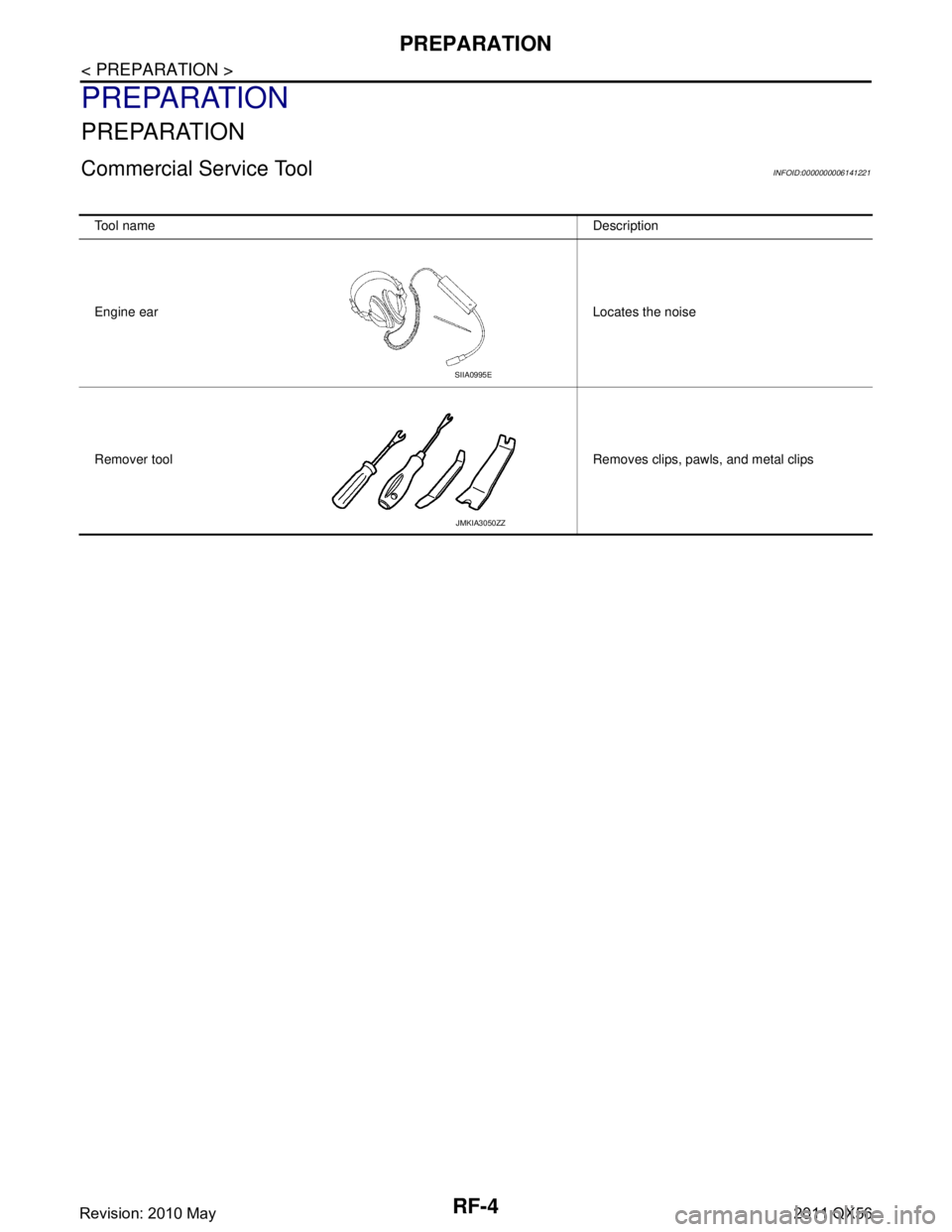
Commercial Service ToolINFOID:0000000006141221
Tool nameDescription
Engine ear Locates the noise
Remover tool Removes clips, pawls, and metal clips
SIIA0995E
JMKIA3050ZZ
Revision: 2010 May2011 QX56
Page 4234 of 5598

RF-20
< DTC/CIRCUIT DIAGNOSIS >
VEHICLE SPEED SIGNAL CIRCUIT
VEHICLE SPEED SIGNAL CIRCUIT
Component Function CheckINFOID:0000000006141233
1.CHECK SUNROOF MOTOR FUNCTION
Check tilt up/down & slide open/close operations with sunroof switch.
Is the inspection result normal?
YES >> GO TO 2.
NO >> Check sunroof switch. Refer to RF-21, "
DiagnosisProcedure".
2.CHECK SUNROOF MOTOR ASSEMBLY INPUT SIGNAL
1. Start engine.
2. Drive the vehicle at more than 40 km/h (25 MPH). CAUTION:
Always drive vehicle at a safe speed.
NOTE:
This procedure may be conducted with the drive wheel s lifted in the shop or by driving the vehicle.
If a road test is expected to be easier , it is unnecessary to lift the vehicle.
3. Check tilt up/down & slide open/clos e operations with sunroof switch.
Is the inspection result normal?
YES >> INSPECTION END
NO >> Refer to RF-20, "
DiagnosisProcedure".
Diagnosis ProcedureINFOID:0000000006141234
SUNROOF MOTOR ASSEMBLY
1.CHECK SUNROOF MOTOR ASSEMBLY INPUT SIGNAL
1. Turn ignition switch OFF.
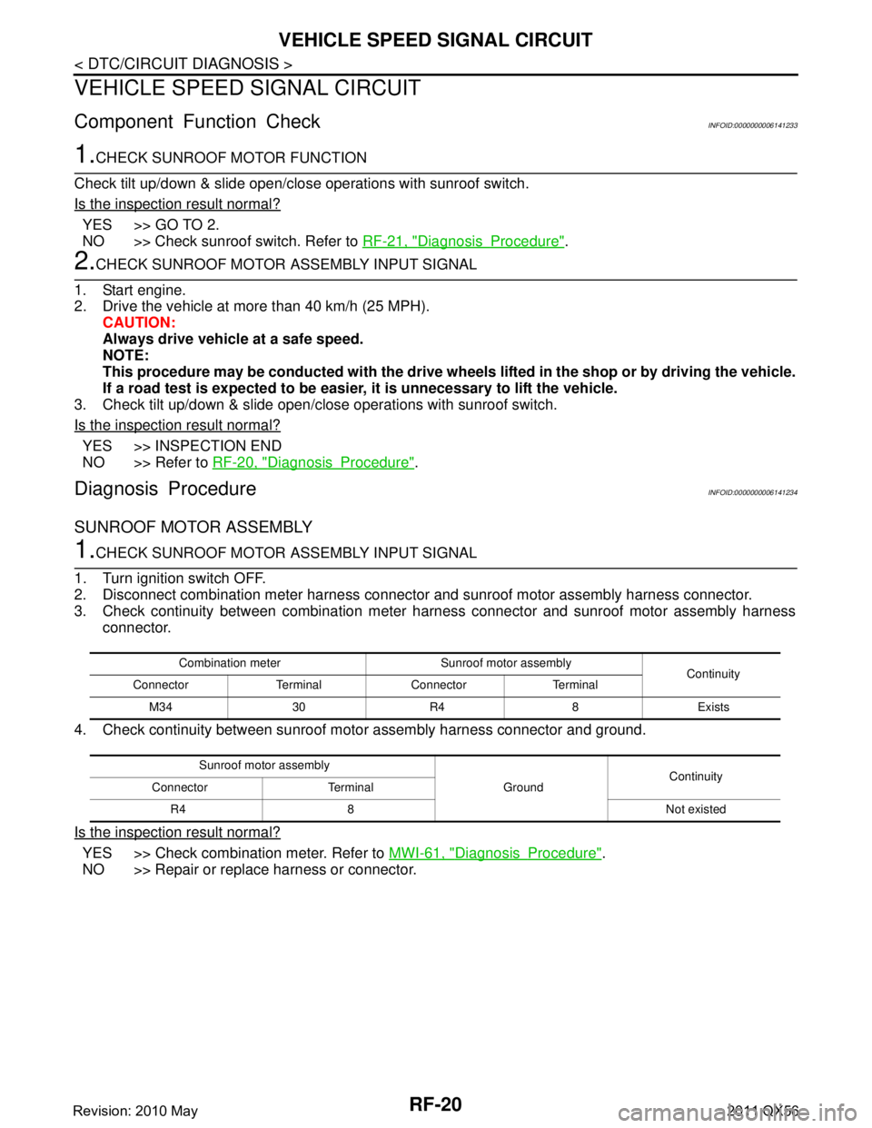
2. Disconnect combination meter harness connector and sunroof motor assembly harness connector.
3. Check continuity between combination meter harness connector and sunroof motor assembly harness connector.
4. Check continuity between sunroof mo tor assembly harness connector and ground.
Is the inspection result normal?
YES >> Check combination meter. Refer to MWI-61, "DiagnosisProcedure".
NO >> Repair or replace harness or connector.
Combination meter Sunroof motor assembly Continuity
Connector Terminal Connector Terminal
M34 30 R4 8 Exists
Sunroof motor assembly GroundContinuity
Connector Terminal
R4 8 Not existed
Revision: 2010 May2011 QX56
Page 4241 of 5598

SQUEAK AND RATTLE TROUBLE DIAGNOSESRF-27
< SYMPTOM DIAGNOSIS >
C
DE
F
G H
I
J
L
M A
B
RF
N
O P
If the noise can be duplicated easily during the test drive, to help identify the source of the noise, try to dupli-
cate the noise with the vehicle stopped by doing one or all of the following items:
1) Close a door.
2) Tap or push/pull around the area where the noise appears to be coming from.
3) Rev the engine.
4) Use a floor jack to recreate vehicle “twist”.
5) At idle, apply engine load (electrical load, half-cl utch on M/T models, drive position on A/T models).
6) Raise the vehicle on a hoist and hit a tire with a rubber hammer.
Drive the vehicle and attempt to duplicate the conditions the customer states exist when the noise occurs.
If it is difficult to duplicate the noise, drive the vehicle slowly on an undulating or rough road to stress the vehicle body.
CHECK RELATED SERVICE BULLETINS
After verifying the customer concern or symptom, che ck ASIST for Technical Service Bulletins (TSBs) related
to the concern or symptom.
If a TSB relates to the symptom, follow the procedure to repair the noise.
LOCATE THE NOISE AND IDENTIFY THE ROOT CAUSE
1. Narrow down the noise to a general area. To help pinpoint the source of the noise, use a listening tool
(Chassis ear: J-39570, engine ear, and mechanics stethoscope).
2. Narrow down the noise to a more specific area and identify the cause of the noise by:
Removing the component(s) in the area that is / are suspected to be the cause of the noise.
Do not use too much force when removing clips and fasteners, otherwise clips and fasteners can be broken
or lost during the repair, resulting in the creation of new noise.
Tapping or pushing/pulling the component(s) that is / are suspected to be the cause of the noise.
Do not tap or push/pull the component(s) with excessive force, otherwise the noise is eliminated only tempo-
rarily.
Feeling for a vibration by hand by touching the component(s ) that is / are suspected to be the cause of the
noise.
Placing a piece of paper between components that are suspected to be the cause of the noise.
Looking for loose components and contact marks. Refer to RF-28, "
Inspection Procedure".
REPAIR THE CAUSE
If the cause is a loose component, tighten the component securely.
If the cause is insufficient clearance between components:
- Separate components by repositioning or loosening and retightening the components, if possible.
- Insulate components with a suitable insulator such as urethane pads, foam blocks, felt cloth tape, or ure-
thane tape. A NISSAN Squeak and Rattle Kit (J-43980) is available through the authorized NISSAN Parts
Department.
CAUTION:
Never use excessive force as many components are constructed of plastic and may be damaged.
NOTE:
Always check with the Parts Department for the latest parts information.
The following materials are contained in the NISSA N Squeak and Rattle Kit (J-43980). Each item can be
ordered separately as needed.
URETHANE PADS [1.5 mm (0.059 in) thick]
Insulates connectors, harness, etc.
76268-9E005: 100 ×135 mm (3.937 ×5.315 in)
76884-71L01: 60 ×85 mm (2.362 ×3.346 in)
76884-71L02: 15 ×25 mm (0.591 ×0.984 in)
INSULATOR (Foam blocks)
Insulates components from contact. Can be used to fill space behind a panel.
73982-9E000: 45 mm (1.772 in) thick, 50 ×50 mm (1.969 ×1.969 in)
73982-50Y00: 10 mm (0.394 in) thick, 50 ×50 mm (1.969 ×1.969 in)
INSULATOR (Light foam block)
80845-71L00: 30 mm (1.181 in) thick, 30 ×50 mm (1.181 ×1.969in)
FELT CLOTHTAPE
Used to insulate where movement does not occur. Ideal for instrument panel applications.
68370-4B000: 15 ×25 mm (0.591 ×0.984 in) pad
68239-13E00: 5 mm (0.197 in) wide tape roll
Revision: 2010 May2011 QX56
Page 4243 of 5598

SQUEAK AND RATTLE TROUBLE DIAGNOSESRF-29
< SYMPTOM DIAGNOSIS >
C
DE
F
G H
I
J
L
M A
B
RF
N
O P
3. Trunk lid torsion bars knocking together
4. A loose license plate or bracket
Most of these incidents can be repaired by adjusting, se curing, or insulating the item(s) or component(s) caus-
ing the noise.
SUNROOF/HEADLINING
Noises in the sunroof / headlining area can of ten be traced to one of the following items:
1. Sunroof lid, rail, linkage, or seals making a rattle or light knocking noise
2. Sunvisor shaft shaking in the holder
3. Front or rear windshield touching headlining and squeaking
Again, pressing on the components to stop the noise while duplicating the conditions can isolate most of these
incidents. Repairs usually consist of insulating with felt cloth tape.
SEATS
When isolating seat noise it is important to note the position the seat is in and the load placed on the seat
when the noise occurs. These conditions should be duplic ated when verifying and isolating the cause of the
noise.
Causes of seat noise include:
1. Headrest rods and holder
2. A squeak between the seat pad cushion and frame
3. The rear seatback lock and bracket
These noises can be isolated by moving or pressing on the suspected components while duplicating the con-
ditions under which the noise occurs. Most of thes e incidents can be repaired by repositioning the component
or applying urethane tape to the contact area.
UNDERHOOD
Some interior noise may be caused by components under the hood or on the engine wall. The noise is then
transmitted into the passenger compartment.
Causes of transmitted underhood noise include:
1. Any component mounted to the engine wall
2. Components that pass through the engine wall
3. Engine wall mounts and connectors
4. Loose radiator mounting pins
5. Hood bumpers out of adjustment
6. Hood striker out of adjustment
These noises can be difficult to isolate since they cannot be reached from the interior of the vehicle. The best
method is to secure, move, or insulate one component at a time and test drive the vehicle. Also, engine RPM
or load can be changed to isolate the noise. Repairs c an usually be made by moving, adjusting, securing, or
insulating the component causing the noise.
Revision: 2010 May2011 QX56
Page 4257 of 5598

RSU-2
< PRECAUTION >
PRECAUTIONS
PRECAUTION
PRECAUTIONS
Precautions for SuspensionINFOID:0000000006225656
• When installing rubber bushings, the final tightening must be carried out under unladen conditions with tires
on ground. Spilled oil might shorten the life of rubber bushings. Be sure to wipe off any spilled oil.
- Unladen conditions mean that fuel, engine coolant and l ubricant are full. Spare tire, jack, hand tools and
mats are in designated positions.
After servicing suspension parts, be sure to check wheel alignment.
Self-lock nuts are not reusable. Always use new ones when installing. Since new self-lock nuts are pre-oiled,
tighten as they are.
Revision: 2010 May2011 QX56