2011 INFINITI QX56 engine
[x] Cancel search: enginePage 4449 of 5598
![INFINITI QX56 2011 Factory Service Manual
POWER SUPPLY AND GROUND CIRCUITSCS-89
< DTC/CIRCUIT DIAGNOSIS > [AIR LEVELIZER CONTROL SYSTEM]
C
D
F
G H
I
J
K L
M A
B
SCS
N
O P
POWER SUPPLY AND GROUND CIRCUIT
Diagnosis ProcedureINFOID:000000000625 INFINITI QX56 2011 Factory Service Manual
POWER SUPPLY AND GROUND CIRCUITSCS-89
< DTC/CIRCUIT DIAGNOSIS > [AIR LEVELIZER CONTROL SYSTEM]
C
D
F
G H
I
J
K L
M A
B
SCS
N
O P
POWER SUPPLY AND GROUND CIRCUIT
Diagnosis ProcedureINFOID:000000000625](/manual-img/42/57033/w960_57033-4448.png)
POWER SUPPLY AND GROUND CIRCUITSCS-89
< DTC/CIRCUIT DIAGNOSIS > [AIR LEVELIZER CONTROL SYSTEM]
C
D
F
G H
I
J
K L
M A
B
SCS
N
O P
POWER SUPPLY AND GROUND CIRCUIT
Diagnosis ProcedureINFOID:0000000006256088
1.CHECK AIR LEVELIZER CONTROL MODUL E IGNITION POWER SUPPLY CIRCUIT
1. Disconnect air levelizer control module connector.
2. Turn ignition switch ON. CAUTION:
Never start the engine.
3. Check voltage between the air levelizer control module harness connector and ground.
Is the inspection result normal?
YES >> INSPECTION END
NO >> GO TO 2.
2.CHECK HARNESS BETWEEN AI R LEVELIZER CONTROL MODULE AND IPDM E/R
1. Turn ignition switch OFF.
2. Disconnect IPDM E/R connector.
3. Check continuity between air levelizer contro l module harness connector and IPDM E/R harness connec-
tor.
4. Check continuity between air levelizer control module harness connector ground.
Is the inspection result normal?
YES >> GO TO 3.
NO >> Repair or replace damaged parts.
3.CHECK IPDM E/R
Check the IPDM E/R. Refer to PCS-10, "
Diagnosis Description".
Is the inspection result normal?
YES >> Check intermittent incident. Refer to GI-40, "Intermittent Incident".
NO >> Repair or replace damaged parts.
Air levelizer control module
—Voltage
Connector Terminal
B84 9 Ground 10 – 16 V
Air levelizer control module IPDM E/R Continuity
Connector Terminal Connector Terminal
B84 9 E10 5 Existed
Air levelizer control module
—Continuity
Connector Terminal
B84 9 Ground Not existed
Revision: 2010 May2011 QX56
Page 4463 of 5598

SE-4
< PRECAUTION >
PRECAUTIONS
PRECAUTION
PRECAUTIONS
Precaution for Supplemental Restraint System (SRS) "AIR BAG" and "SEAT BELT
PRE-TENSIONER"
INFOID:0000000006237842
The Supplemental Restraint System such as “A IR BAG” and “SEAT BELT PRE-TENSIONER”, used along
with a front seat belt, helps to reduce the risk or severi ty of injury to the driver and front passenger for certain
types of collision. This system includes seat belt switch inputs and dual stage front air bag modules. The SRS
system uses the seat belt switches to determine the front air bag deployment, and may only deploy one front
air bag, depending on the severity of a collision and w hether the front occupants are belted or unbelted.
Information necessary to service the system safely is included in the “SRS AIR BAG” and “SEAT BELT” of this
Service Manual.
WARNING:
• To avoid rendering the SRS inopera tive, which could increase the risk of personal injury or death in
the event of a collision that would result in air bag inflation, all maintenance must be performed by
an authorized NISS AN/INFINITI dealer.
Improper maintenance, including in correct removal and installation of the SRS, can lead to personal
injury caused by unintent ional activation of the system. For re moval of Spiral Cable and Air Bag
Module, see the “SRS AIR BAG”.
Do not use electrical test equipmen t on any circuit related to the SRS unless instructed to in this
Service Manual. SRS wiring harnesses can be identi fied by yellow and/or orange harnesses or har-
ness connectors.
PRECAUTIONS WHEN USING POWER TOOLS (AIR OR ELECTRIC) AND HAMMERS
WARNING:
When working near the Air Bag Diagnosis Sensor Unit or other Air Bag System sensors with the ignition ON or engine running, DO NOT use air or electric power tools or strike near the sensor(s)
with a hammer. Heavy vibration could activate the sensor(s) and deploy the air bag(s), possibly
causing serious injury.
When using air or electric power tools or hammers , always switch the ignition OFF, disconnect the
battery, and wait at least 3 minu tes before performing any service.
Service NoticeINFOID:0000000006217352
When removing or installing various parts, place a cloth or padding onto the vehicle body to prevent
scratches.
Handle trim, molding, instruments, grille, etc. carefull y during removing or installing. Be careful not to oil or
damage them.
Apply sealing compound where necessary when installing parts.
When applying sealing compound, be careful that t he sealing compound never protrudes from parts.
When replacing any metal parts (for example body outer panel, members, etc.), always take rust prevention
measures.
Precaution for WorkINFOID:0000000006217353
When removing or disassembling each component, be careful not to damage or deform it. If a component
may be subject to interference, al ways protect it with a shop cloth.
When removing (disengaging) components with a screwdriver or similar tool, always wrap the component
with a shop cloth or vinyl tape to protect it.
Protect the removed parts with a shop cloth and keep them.
Replace a deformed or damaged clip.
If a part is specified as a non-reusable part, always replace it with new one.
Always tighten bolts and nuts securely to the specified torque.
After reinstallation is complete, always check that each part works normally.
Follow the steps below to clean components.
- Water soluble foul: Dip a soft cloth into lukewarm water, and wring the water out of the cloth to wipe the fouled area.
Then rub with a soft and dry cloth.
Revision: 2010 May2011 QX56
Page 4465 of 5598
SE-6
< PREPARATION >
PREPARATION
PREPARATION
PREPARATION
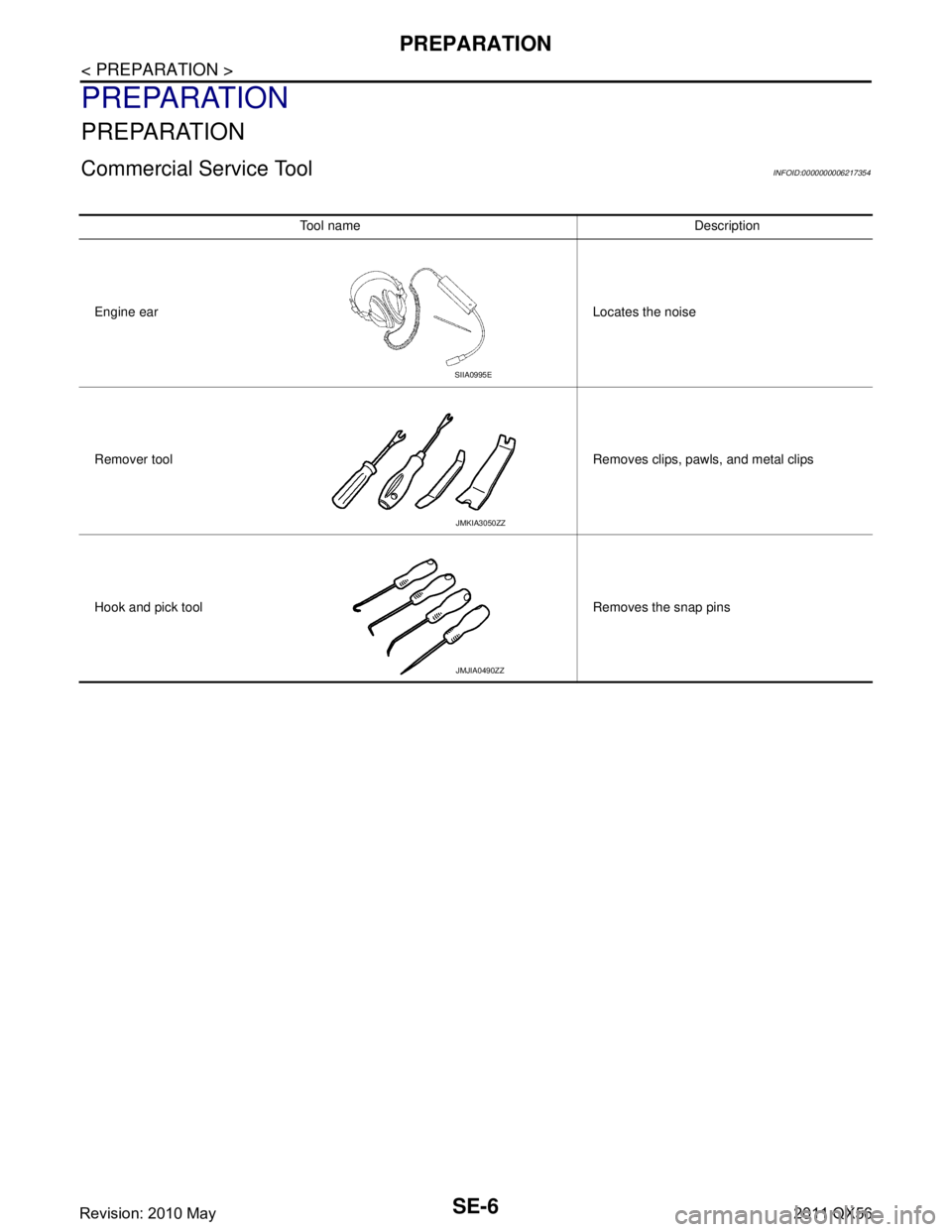
Commercial Service ToolINFOID:0000000006217354
Tool name Description
Engine ear Locates the noise
Remover tool Removes clips, pawls, and metal clips
Hook and pick tool Removes the snap pins
SIIA0995E
JMKIA3050ZZ
JMJIA0490ZZ
Revision: 2010 May2011 QX56
Page 4473 of 5598
SE-14
< SYSTEM DESCRIPTION >
COMPONENT PARTS
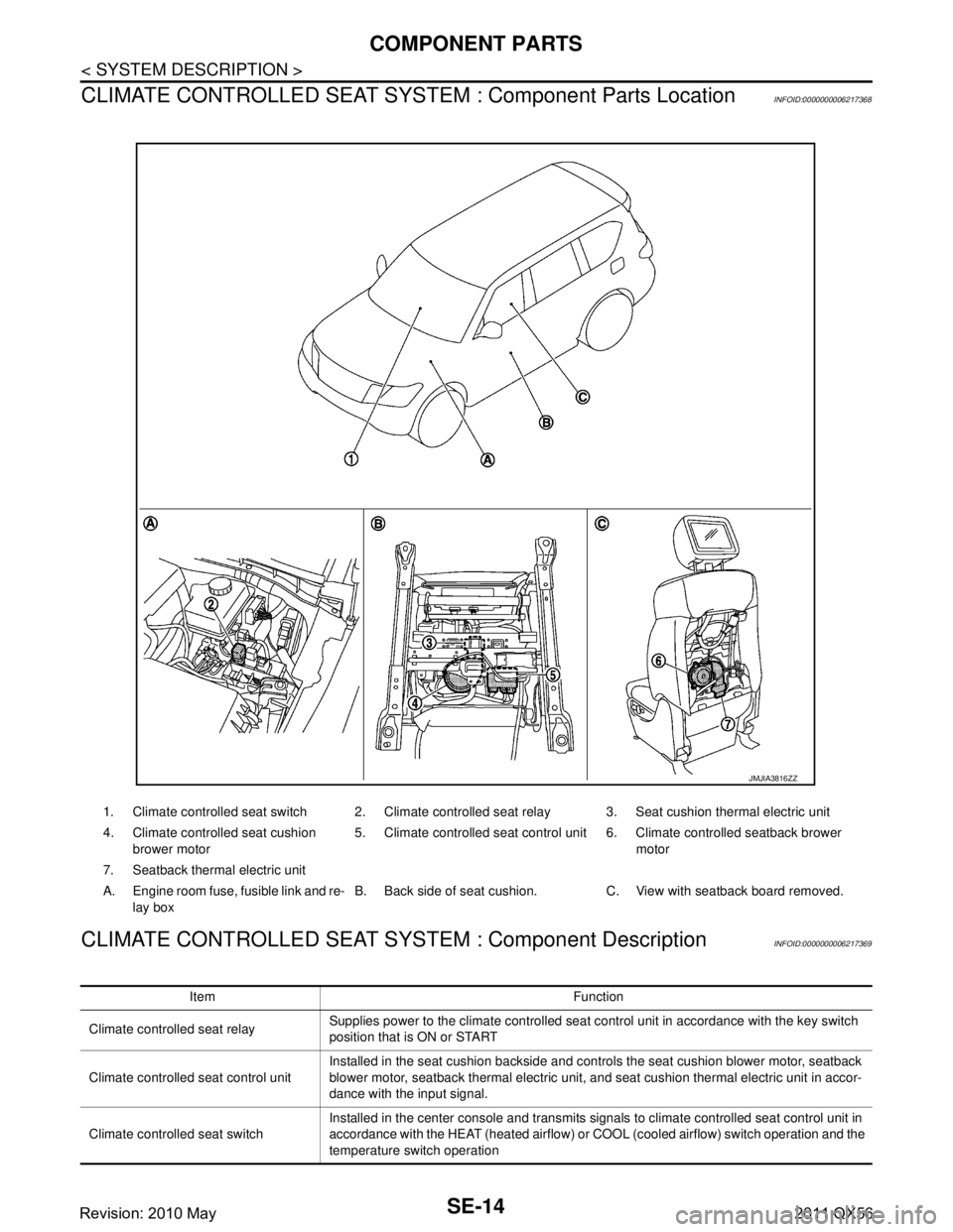
CLIMATE CONTROLLED SEAT SYSTEM : Component Parts Location
INFOID:0000000006217368
CLIMATE CONTROLLED SEAT SYSTEM : Component DescriptionINFOID:0000000006217369
1. Climate controlled seat switch 2. Climate controlled seat relay 3. Seat cushion thermal electric unit
4. Climate controlled seat cushion
brower motor 5. Climate controlled seat control unit 6. Climate controlled seatback brower
motor
7. Seatback thermal electric unit
A. Engine room fuse, fusible link and re- lay box B. Back side of seat cushion. C. View with seatback board removed.
JMJIA3816ZZ
Item Function
Climate controlled seat relay Supplies power to the climate controlled seat control unit in accordance with the key switch
position that is ON or START
Climate controlled seat control unit Installed in the seat cushion backside and controls the seat cushion blower motor, seatback
blower motor, seatback thermal electric unit, and seat cushion thermal electric unit in accor-
dance with the input signal.
Climate controlled seat switch Installed in the center console and transmits signals to climate controlled seat control unit in
accordance with the HEAT (heated airflow) or COOL (cooled airflow) switch operation and the
temperature switch operation
Revision: 2010 May2011 QX56
Page 4559 of 5598
SE-100
< SYMPTOM DIAGNOSIS >
SQUEAK AND RATTLE TROUBLE DIAGNOSES
If the noise can be duplicated easily during the test drive, to help identify the source of the noise, try to dupli-
cate the noise with the vehicle stopped by doing one or all of the following:
1) Close a door.
2) Tap or push/pull around the area where the noise appears to be coming from.
3) Rev the engine.
4) Use a floor jack to recreate vehicle “twist”.
5) At idle, apply engine load (electrical load, half-cl utch on M/T models, drive position on A/T models).
6) Raise the vehicle on a hoist and hit a tire with a rubber hammer.
Drive the vehicle and attempt to duplicate the conditions the customer states exist when the noise occurs.
If it is difficult to duplicate the noise, drive the v ehicle slowly on an undulating or rough road to stress the
vehicle body.
CHECK RELATED SERVICE BULLETINS
After verifying the customer concern or symptom, chec k ASIST for Technical Service Bulletins (TSBs) related
to that concern or symptom.
If a TSB relates to the symptom, follo w the procedure to repair the noise.
LOCATE THE NOISE AND IDENTIFY THE ROOT CAUSE
1. Narrow down the noise to a general area. To help pi npoint the source of the noise, use a listening tool
(Chassis ear: J-39570, Engine ear and mechanics stethoscope).
2. Narrow down the noise to a more specific area and identify the cause of the noise by:
Removing the components in the area that is are suspected to be the cause of the noise.
Do not use too much force when removing clips and fasteners, otherwise clips and fastener can be broken
or lost during the repair, resulting in the creation of new noise.
Tapping or pushing/pulling the component that is are suspected to be the cause of the noise.
Do not tap or push/pull the component with excessive force, otherwise the noise will be eliminated only tem-
porarily.
Feeling for a vibration by hand by touching the component (s) that is are suspected to be the cause of the
noise.
Placing a piece of paper between components that are suspected to be the cause of the noise.
Looking for loose components and contact marks. Refer to SE-101, "
Inspection Procedure".
REPAIR THE CAUSE
If the cause is a loose component, tighten the component securely.
If the cause is insufficient clearance between components:
- Separate components by repositioning or loos ening and retightening the component, if possible.
- Insulate components with a suitable insulator such as urethane pads, foam blocks, felt cloth tape or ure-
thane tape. A Nissan Squeak and Rattle Kit (J-43980) is available through the authorized Nissan Parts
Department.
CAUTION:
Never use excessive force as many components are constructed of plastic and may be damaged.
NOTE:
Always check with the Parts Departm ent for the latest parts information.
The following materials are contained in the Nissan Squeak and Rattle Kit (J-43980). Each item can be
ordered separately as needed.
URETHANE PADS [1.5 mm (0.059 in) thick]
Insulates connectors, harness, etc.
76268-9E005: 100 ×135 mm (3.94 ×5.31 in)/76884-71L01: 60 ×85 mm (2.36 ×3.35 in)/76884-
71L02:15 ×25 mm (0.59 ×0.98 in)
INSULATOR (Foam blocks)
Insulates components from contact. Can be used to fill space behind a panel.
73982-9E000: 45 mm (1.77 in) thick, 50 ×50 mm (1.97 ×1.97 in)/73982-
50Y00: 10 mm (0.39 in) thick, 50 ×50 mm (1.97 ×1.97 in)
INSULATOR (Light foam block)
80845-71L00: 30 mm (1.18 in) thick, 30 ×50 mm (1.18 ×1.97in)
FELT CLOTHTAPE
Used to insulate where movement does not occu r. Ideal for instrument panel applications.
68370-4B000: 15 ×25 mm (0.59 ×0.98 in) pad/68239-13E00: 5 mm (0.20 in) wide tape roll
The following materials, not found in the kit, can also be used to repair squeaks and rattles.
UHMW (TEFLON) TAPE
Revision: 2010 May2011 QX56
Page 4561 of 5598

SE-102
< SYMPTOM DIAGNOSIS >
SQUEAK AND RATTLE TROUBLE DIAGNOSES
Most of these incidents can be repaired by adjusting, securing or insulating the item(s) or component(s) caus-
ing the noise.
SUNROOF/HEADLINING
Noises in the sunroof/headlining area c an often be traced to one of the following:
1. Sunroof lid, rail, linkage or seals making a rattle or light knocking noise
2. Sunvisor shaft shaking in the holder
3. Front or rear windshield touching headlining and squeaking
Again, pressing on the components to stop the noise while duplicating the conditions can isolate most of these
incidents. Repairs usually consist of insulating with felt cloth tape.
SEATS
When isolating seat noise it's important to note the position the seats in and the load placed on the seat when
the noise occurs. These conditions should be duplicated when verifying and isolating the cause of the noise.
Cause of seat noise include:
1. Headrest rods and holder
2. A squeak between the seat pad cushion and frame
3. The rear seatback lock and bracket
These noises can be isolated by moving or pressing on the suspected components while duplicating the con-
ditions under which the noise occurs.Most of these incidents can be repaired by repositioning the component
or applying urethane tape to the contact area.
UNDERHOOD
Some interior noise may be caused by components under the hood or on the engine wall. The noise is then
transmitted into the passenger compartment.
Causes of transmitted underhood noise include:
1. Any component mounted to the engine wall
2. Components that pass through the engine wall
3. Engine wall mounts and connectors
4. Loose radiator mounting pins
5. Hood bumpers out of adjustment
6. Hood striker out of adjustment
These noises can be difficult to isolate since they cannot be reached from the interior of the vehicle. The best
method is to secure, move or insulate one component at a time and test drive the \
vehicle. Also, engine RPM
or load can be changed to isolate the noise. Repairs can usually be made by moving, adjusting, securing, or
insulating the component causing the noise.
Revision: 2010 May2011 QX56
Page 4608 of 5598
SEC-1
BODY EXTERIOR, DOORS, ROOF & VEHICLE SECURITY
C
D
E
F
G H
I
J
L
M
SECTION SEC
A
B
SEC
N
O P
CONTENTS
SECURITY CONTROL SYSTEM
WITH INTELLIGE NT KEY SYSTEM
PRECAUTION ................ ...............................
5
PRECAUTIONS .............................................. .....5
Precaution for Supplemental Restraint System
(SRS) "AIR BAG" and "SEAT BELT PRE-TEN-
SIONER" ............................................................. ......
5
Precaution Necessary for Steering Wheel Rota-
tion after Battery Disconnect .....................................
5
Precaution for Procedure without Cowl Top Cover ......6
SYSTEM DESCRIPTION ..............................7
COMPONENT PARTS ................................... .....7
Component Parts Location .................................. ......7
Component Description .............................................8
A/T Shift Selector (Detention Switch) ........................8
BCM ..........................................................................8
ECM ..........................................................................9
IPDM E/R ..................................................................9
NATS Antenna Amp. .................................................9
TCM ..........................................................................9
Combination Meter ....................................................9
Door Switch ...............................................................9
Hood Switch ..............................................................9
Inside Key Antenna ...................................................9
Intelligent Key ............................................................9
Push-button Ignition Switch .....................................10
Remote Keyless Entry Receiver .............................10
Security Indicator Lamp ..........................................10
Starter Control Relay ...............................................10
Starter Relay ...........................................................10
Steering Lock Relay ................................................10
Steering Lock Unit ...................................................10
Stop Lamp Switch ...................................................10
Transmission Range Switch ....................................10
Vehicle Information Display .....................................11
SYSTEM .............................................................12
INTELLIGENT KEY SYSTEM/ENGINE START
FUNCTION ............................................................. ....
12
INTELLIGENT KEY SYSTEM/ENGINE START
FUNCTION : System Diagram ................................
12
INTELLIGENT KEY SYSTEM/ENGINE START
FUNCTION : System Description ............................
12
INFINITI VEHICLE IMMOBILIZER SYSTEM-NATS ....14
INFINITI VEHICLE IMMOBILIZER SYSTEM-
NATS : System Diagram .........................................
15
INFINITI VEHICLE IMMOBILIZER SYSTEM-
NATS : System Description .....................................
15
VEHICLE SECURITY SYSTEM .................................17
VEHICLE SECURITY SYSTEM : System Dia-
gram .................................................................... ....
17
VEHICLE SECURITY SYSTEM : System Descrip-
tion ...........................................................................
18
DIAGNOSIS SYSTEM (BCM) ...........................21
COMMON ITEM ..................................................... ....21
COMMON ITEM : CONSULT-III Function (BCM -
COMMON ITEM) .....................................................
21
INTELLIGENT KEY ................................................ ....22
INTELLIGENT KEY : CONSULT-III Function
(BCM - INTELLIGENT KEY) ....................................
22
THEFT ALM ........................................................... ....26
THEFT ALM : CONSULT-III Function (BCM -
THEFT) ................................................................ ....
26
IMMU ...................................................................... ....27
IMMU : CONSULT-III Function (BCM - IMMU) ........27
DIAGNOSIS SYSTEM (IPDM E/R) ...................28
CONSULT-III Function (IPDM E/R) .........................28
ECU DIAGNOSIS INFORMATION ..............30
ECM, IPDM E/R, BCM .......................................30
List of ECU Reference ......................................... ....30
Revision: 2010 May2011 QX56
Page 4610 of 5598
SEC-3
C
DE
F
G H
I
J
L
M A
B
SEC
N
O P
B260F ENGINE STATUS ............................... ..101
Description .......................................................... ..101
DTC Logic .............................................................101
Diagnosis Procedure .............................................101
B2612 STEERING STATUS .............................102
DTC Logic ........................................................... ..102
Diagnosis Procedure .............................................102
B2619 BCM ......................................................105
DTC Logic ........................................................... ..105
Diagnosis Procedure .............................................105
B26E9 STEERING STATUS ............................106
DTC Logic ........................................................... ..106
Diagnosis Procedure .............................................106
B26EF STEERING LOCK RELAY ...................107
DTC Logic ........................................................... ..107
Diagnosis Procedure .............................................107
B26F0 STEERING LOCK RELAY ...................109
DTC Logic ........................................................... ..109
Diagnosis Procedure .............................................109
B26F3 STARTER CONTROL RELAY .............111
DTC Logic ........................................................... ..111
Diagnosis Procedure .............................................111
B26F4 STARTER CONTROL RELAY .............112
DTC Logic ........................................................... ..112
Diagnosis Procedure .............................................112
B26F5 STEERING LOCK STATUS SWITCH ..113
DTC Logic .............................................................113
Diagnosis Procedure .............................................113
B26F7 BCM ......................................................116
DTC Logic ........................................................... ..116
Diagnosis Procedure .............................................116
B26F8 BCM ......................................................117
DTC Logic ........................................................... ..117
Diagnosis Procedure .............................................117
B26F9 CRANKING REQUEST CIRCUIT .........118
DTC Logic ........................................................... ..118
Diagnosis Procedure .............................................118
B26FA CRANKING REQUEST CIRCUIT ........120
DTC Logic ........................................................... ..120
Diagnosis Procedure .............................................120
B26FC KEY REGISTRATION ..........................122
DTC Logic ........................................................... ..122
Diagnosis Procedure .............................................122
B209F CRANKING REQUEST CIRCUIT .........123
DTC Logic ........................................................... ..123
Diagnosis Procedure .............................................123
B20A0 CRANKING REQUEST CIRCUIT .......125
DTC Logic ............................................................ ..125
Diagnosis Procedure .............................................125
B2108 STEERING LOCK RELAY ..................127
DTC Logic ..............................................................127
Diagnosis Procedure .............................................127
B2109 STEERING LOCK RELAY ..................128
DTC Logic ..............................................................128
Diagnosis Procedure .............................................128
B210A STEERING LOCK UNIT ......................129
DTC Logic ..............................................................129
Diagnosis Procedure .............................................129
B210B STARTER CONTROL RELAY ............131
DTC Logic ..............................................................131
Diagnosis Procedure .............................................131
B210C STARTER CONTROL RELAY ............132
DTC Logic ..............................................................132
Diagnosis Procedure .............................................132
B210D STARTER RELAY ..............................133
DTC Logic ..............................................................133
Diagnosis Procedure .............................................133
B210E STARTER RELAY ...............................134
DTC Logic ..............................................................134
Diagnosis Procedure .............................................134
B210F SHIFT POSITION/CLUTCH INTER-
LOCK SWITCH ...............................................
136
DTC Logic ..............................................................136
Diagnosis Procedure .............................................136
B2110 SHIFT POSITION/CLUTCH INTER-
LOCK SWITCH ...............................................
138
DTC Logic ..............................................................138
Diagnosis Procedure .............................................138
HEADLAMP FUNCTION .................................140
Component Function Check ..................................140
Diagnosis Procedure .............................................140
HOOD SWITCH ...............................................141
Component Function Check ................................141
Diagnosis Procedure ............................................141
Component Inspection ...........................................142
HORN FUNCTION ...........................................143
Component Function Check .............................. ..143
Diagnosis Procedure ............................................143
Component Inspection ...........................................145
SECURITY INDICATOR LAMP ......................146
Component Function Check ................................146
Diagnosis Procedure .............................................146
SYMPTOM DIAGNOSIS ............................148
Revision: 2010 May2011 QX56