Page 3814 of 5598

MWI
OIL PRESSURE SWITCH SIGNAL CIRCUIT
MWI-71
< DTC/CIRCUIT DIAGNOSIS >
C
D E
F
G H
I
J
K L
M B A
O P
OIL PRESSURE SWITCH SIGNAL CIRCUIT
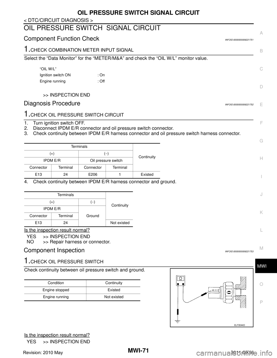
Component Function CheckINFOID:0000000006221751
1.CHECK COMBINATION METER INPUT SIGNAL
Select the “Data Monitor” for the “METER/M& A” and check the “OIL W/L” monitor value.
>> INSPECTION END
Diagnosis ProcedureINFOID:0000000006221752
1.CHECK OIL PRESSURE SWITCH CIRCUIT
1. Turn ignition switch OFF.
2. Disconnect IPDM E/R connector and oil pressure switch connector.
3. Check continuity between IPDM E/R harness c onnector and oil pressure switch harness connector.
4. Check continuity between IPDM E/R harness connector and ground.
Is the inspection result normal?
YES >> INSPECTION END
NO >> Repair harness or connector.
Component InspectionINFOID:0000000006221753
1.CHECK OIL PRESSURE SWITCH
Check continuity between oil pressure switch and ground.
Is the inspection result normal?
YES >> INSPECTION END
“OIL W/L”
Ignition switch ON : On
Engine running : Off
Te r m i n a l s Continuity
(+) (
−)
IPDM E/R Oil pressure switch
Connector Terminal Connector Terminal E1324E2061Existed
Te r m i n a l s Continuity
(+) (
−)
IPDM E/R Ground
Connector Terminal
E13 24 Not existed
Condition Continuity
Engine stopped Existed Engine running Not existed
ELF0044D
Revision: 2010 May2011 QX56
Page 3822 of 5598

MWI
THE OIL PRESSURE WARNING LAMP DOES NOT TURN OFFMWI-79
< SYMPTOM DIAGNOSIS >
C
DE
F
G H
I
J
K L
M B A
O P
THE OIL PRESSURE WARNING LAMP DOES NOT TURN OFF
DescriptionINFOID:0000000006221765
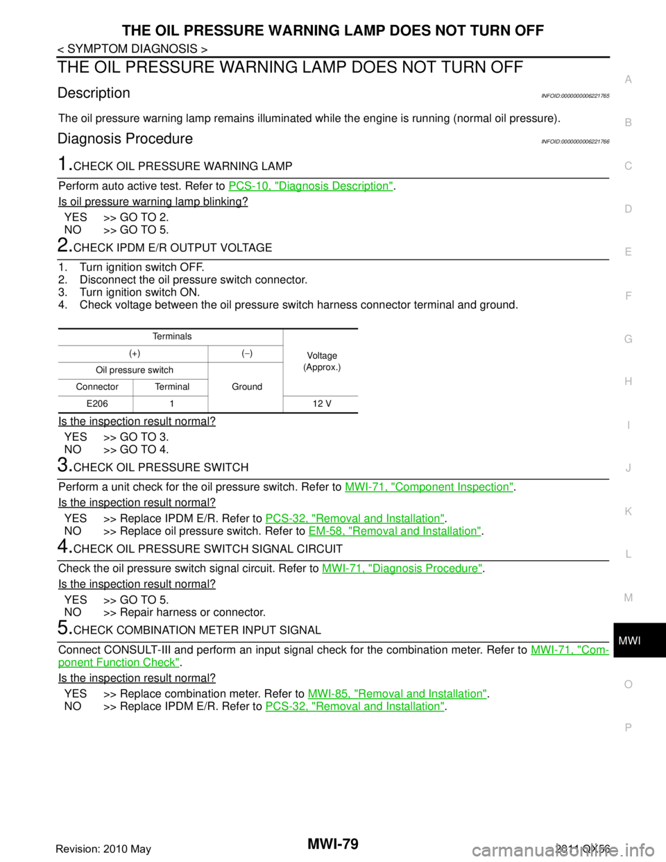
The oil pressure warning lamp remains illuminated while the engine is running (normal oil pressure).
Diagnosis ProcedureINFOID:0000000006221766
1.CHECK OIL PRESSURE WARNING LAMP
Perform auto active test. Refer to PCS-10, "
Diagnosis Description".
Is oil pressure warning lamp blinking?
YES >> GO TO 2.
NO >> GO TO 5.
2.CHECK IPDM E/R OUTPUT VOLTAGE
1. Turn ignition switch OFF.
2. Disconnect the oil pressure switch connector.
3. Turn ignition switch ON.
4. Check voltage between the oil pressure switch harness connector terminal and ground.
Is the inspection result normal?
YES >> GO TO 3.
NO >> GO TO 4.
3.CHECK OIL PRESSURE SWITCH
Perform a unit check for the oil pressure switch. Refer to MWI-71, "
Component Inspection".
Is the inspection result normal?
YES >> Replace IPDM E/R. Refer to PCS-32, "Removal and Installation".
NO >> Replace oil pressure switch. Refer to EM-58, "
Removal and Installation".
4.CHECK OIL PRESSURE SWITCH SIGNAL CIRCUIT
Check the oil pressure switch signal circuit. Refer to MWI-71, "
Diagnosis Procedure".
Is the inspection result normal?
YES >> GO TO 5.
NO >> Repair harness or connector.
5.CHECK COMBINATION METER INPUT SIGNAL
Connect CONSULT-III and perform an input signal check for the combination meter. Refer to MWI-71, "
Com-
ponent Function Check".
Is the inspection result normal?
YES >> Replace combination meter. Refer to MWI-85, "Removal and Installation".
NO >> Replace IPDM E/R. Refer to PCS-32, "
Removal and Installation".
Te r m i n a l s
Voltag e
(Approx.)
(+) (
−)
Oil pressure switch Ground
Connector Terminal
E206 1 12 V
Revision: 2010 May2011 QX56
Page 3823 of 5598

MWI-80
< SYMPTOM DIAGNOSIS >
THE PARKING BRAKE RELEASE WARNING CONTINUES DISPLAYING, OR
DOES NOT DISPLAY
THE PARKING BRAKE RELEASE WA RNING CONTINUES DISPLAYING,
OR DOES NOT DISPLAY
DescriptionINFOID:0000000006221767
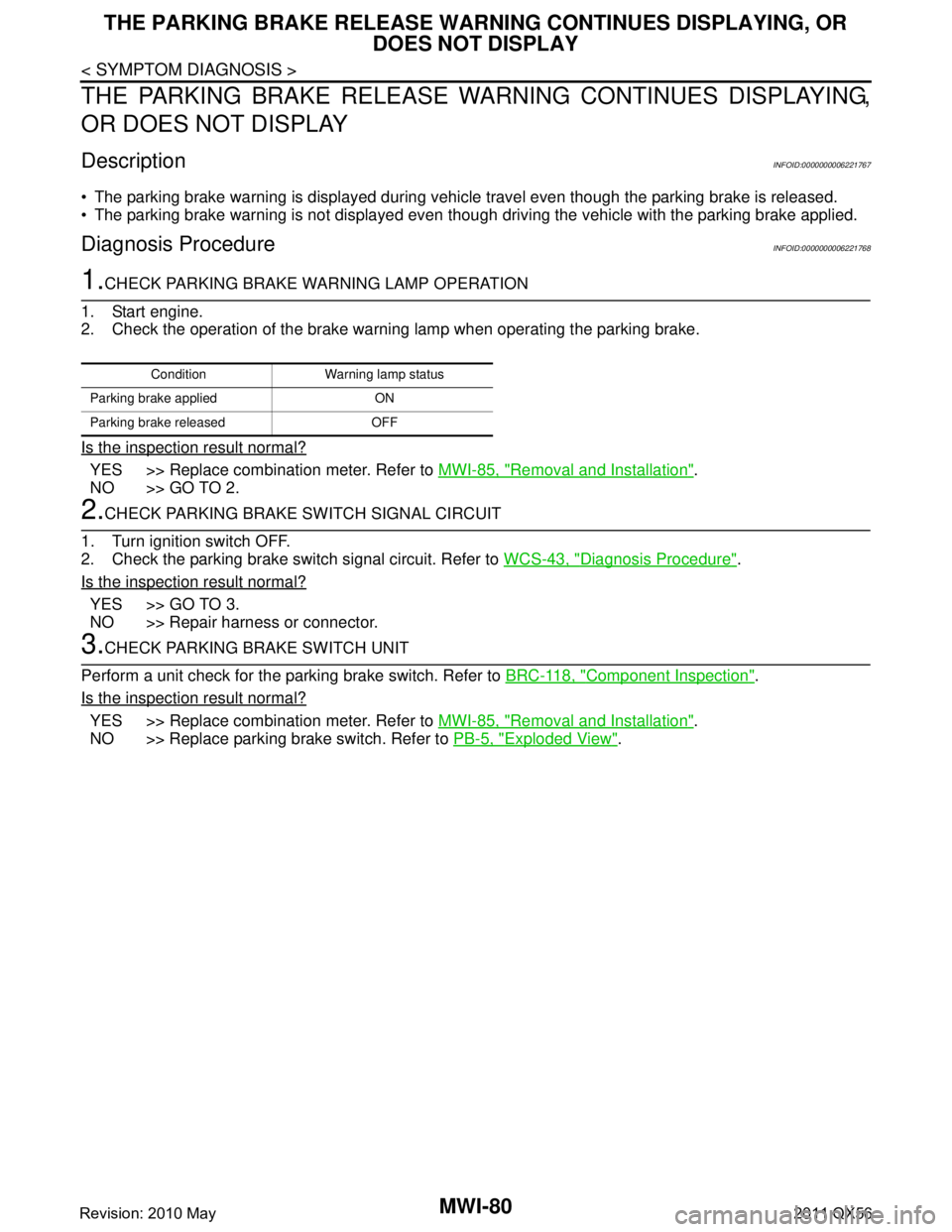
The parking brake warning is displayed during vehi cle travel even though the parking brake is released.
The parking brake warning is not displayed even though driving the vehicle with the parking brake applied.
Diagnosis ProcedureINFOID:0000000006221768
1.CHECK PARKING BRAKE WARNING LAMP OPERATION
1. Start engine.
2. Check the operation of the brake warni ng lamp when operating the parking brake.
Is the inspection result normal?
YES >> Replace combination meter. Refer to MWI-85, "Removal and Installation".
NO >> GO TO 2.
2.CHECK PARKING BRAKE SWITCH SIGNAL CIRCUIT
1. Turn ignition switch OFF.
2. Check the parking brake switch signal circuit. Refer to WCS-43, "
Diagnosis Procedure".
Is the inspection result normal?
YES >> GO TO 3.
NO >> Repair harness or connector.
3.CHECK PARKING BRAKE SWITCH UNIT
Perform a unit check for the parking brake switch. Refer to BRC-118, "
Component Inspection".
Is the inspection result normal?
YES >> Replace combination meter. Refer to MWI-85, "Removal and Installation".
NO >> Replace parking brake switch. Refer to PB-5, "
Exploded View".
Condition Warning lamp status
Parking brake applied ON
Parking brake released OFF
Revision: 2010 May2011 QX56
Page 3844 of 5598
![INFINITI QX56 2011 Factory Service Manual
PCS
PRECAUTIONSPCS-3
< PRECAUTION > [IPDM E/R]
C
D
E
F
G H
I
J
K L
B A
O P
N
PRECAUTION
PRECAUTIONS
Precaution for Supplemental
Restraint System (SRS) "AIR BAG" and "SEAT BELT
PRE-TENSIONER"
INFOID INFINITI QX56 2011 Factory Service Manual
PCS
PRECAUTIONSPCS-3
< PRECAUTION > [IPDM E/R]
C
D
E
F
G H
I
J
K L
B A
O P
N
PRECAUTION
PRECAUTIONS
Precaution for Supplemental
Restraint System (SRS) "AIR BAG" and "SEAT BELT
PRE-TENSIONER"
INFOID](/manual-img/42/57033/w960_57033-3843.png)
PCS
PRECAUTIONSPCS-3
< PRECAUTION > [IPDM E/R]
C
D
E
F
G H
I
J
K L
B A
O P
N
PRECAUTION
PRECAUTIONS
Precaution for Supplemental
Restraint System (SRS) "AIR BAG" and "SEAT BELT
PRE-TENSIONER"
INFOID:0000000006220159
The Supplemental Restraint System such as “A IR BAG” and “SEAT BELT PRE-TENSIONER”, used along
with a front seat belt, helps to reduce the risk or severi ty of injury to the driver and front passenger for certain
types of collision. This system includes seat belt switch inputs and dual stage front air bag modules. The SRS
system uses the seat belt switches to determine the front air bag deployment, and may only deploy one front
air bag, depending on the severity of a collision and whether the front occupants are belted or unbelted.
Information necessary to service the system safely is included in the “SRS AIR BAG” and “SEAT BELT” of this
Service Manual.
WARNING:
• To avoid rendering the SRS inoper ative, which could increase the risk of personal injury or death in
the event of a collision that would result in air ba g inflation, all maintenance must be performed by
an authorized NISSAN/INFINITI dealer.
Improper maintenance, including in correct removal and installation of the SRS, can lead to personal
injury caused by unintentional act ivation of the system. For removal of Spiral Cable and Air Bag
Module, see the “SRS AIR BAG”.
Do not use electrical test equipm ent on any circuit related to the SRS unless instructed to in this
Service Manual. SRS wiring harnesses can be identi fied by yellow and/or orange harnesses or har-
ness connectors.
PRECAUTIONS WHEN USING POWER TOOLS (AIR OR ELECTRIC) AND HAMMERS
WARNING:
When working near the Air Bag Diagnosis Sensor Unit or other Air Bag System sensors with the
ignition ON or engine running, DO NOT use air or electric power tools or strike near the sensor(s)
with a hammer. Heavy vibration could activate the sensor(s) and deploy the air bag(s), possibly
causing serious injury.
When using air or electric power tools or hammers , always switch the ignition OFF, disconnect the
battery, and wait at least 3 minutes before performing any service.
Revision: 2010 May2011 QX56
Page 3845 of 5598
PCS-4
< SYSTEM DESCRIPTION >[IPDM E/R]
COMPONENT PARTS
SYSTEM DESCRIPTION
COMPONENT PARTS
Component Parts LocationINFOID:0000000006220160
1. IPDM E/R
A. Engine room (RH)
JMMIA0330ZZ
Revision: 2010 May2011 QX56
Page 3851 of 5598
![INFINITI QX56 2011 Factory Service Manual
PCS-10
< SYSTEM DESCRIPTION >[IPDM E/R]
DIAGNOSIS SYSTEM (IPDM E/R)
DIAGNOSIS SYSTEM (IPDM E/R)
Diagnosis DescriptionINFOID:0000000006220170
AUTO ACTIVE TEST
Description
In auto active test, the IPDM INFINITI QX56 2011 Factory Service Manual
PCS-10
< SYSTEM DESCRIPTION >[IPDM E/R]
DIAGNOSIS SYSTEM (IPDM E/R)
DIAGNOSIS SYSTEM (IPDM E/R)
Diagnosis DescriptionINFOID:0000000006220170
AUTO ACTIVE TEST
Description
In auto active test, the IPDM](/manual-img/42/57033/w960_57033-3850.png)
PCS-10
< SYSTEM DESCRIPTION >[IPDM E/R]
DIAGNOSIS SYSTEM (IPDM E/R)
DIAGNOSIS SYSTEM (IPDM E/R)
Diagnosis DescriptionINFOID:0000000006220170
AUTO ACTIVE TEST
Description
In auto active test, the IPDM E/R sends a drive si
gnal to the following systems to check their operation.
Oil pressure warning lamp
Rear window defogger
Front wiper (LO, HI)
Parking lamp
License plate lamp
Tail lamp
Side marker lamp
Front fog lamp
Headlamp (LO, HI)
A/C compressor (magnet clutch)
Operation Procedure
CAUTION:
Never perform auto active test in the following conditions.
Engine is running.
CONSULT-III is connected.
1. Close the hood and lift the wiper arms from the windshield. (Prevent windshield damage due to wiper
operation)
NOTE:
When auto active test is performed with hood opened, sprinkle water on windshield beforehand.
2. Turn the ignition switch OFF.
3. Turn the ignition switch ON, and within 20 seconds, pr ess the driver door switch 10 times. Then turn the
ignition switch OFF.
CAUTION:
Close passenger door.
4. Turn the ignition switch ON within 10 seconds. Af ter that the horn sounds once and the auto active test
starts.
CAUTION:
Engine starts when igniti on switch is turned ON while brake pedal is depressed.
5. The oil pressure warning lamp starts blinking when the auto active test starts.
6. After a series of the following operations is repeated 3 times, auto active test is completed.
NOTE:
When auto active test has to be cancelled halfway through test, turn the ignition switch OFF.
When auto active test is not activated, door swit ch may be the cause. Check door switch. Refer to DLK-117,
"ComponentFunctionCheck".
Inspection in Auto Active Test
When auto active test is actuated, the following operation sequence is repeated 3 times.
Operation
sequence Inspection location Operation
1 Oil pressure warning lamp Blinks continuously during operation of auto active test
2 Rear window defogger 10 seconds
3 Front wiper LO for 5 seconds → HI for 5 seconds
4 Parking lamp
License plate lamp
Tail lamp
Side marker lamp
Front fog lamp 10 seconds
Revision: 2010 May2011 QX56
Page 3855 of 5598
PCS-14
< SYSTEM DESCRIPTION >[IPDM E/R]
DIAGNOSIS SYSTEM (IPDM E/R)
*: Operates while the engine is running.EXTERNAL LAMPS
Off OFF
TAIL Operates the tail lamp relay.
Lo Operates the headlamp low relay.
Hi
Operates the headlamp low relay and ON/OFF the headlamp high relay at 1 sec-
ond intervals.
Fog Operates the front fog lamp relay.
Test item Operation Description
Revision: 2010 May2011 QX56
Page 3856 of 5598
![INFINITI QX56 2011 Factory Service Manual
PCS
IPDM E/RPCS-15
< ECU DIAGNOSIS INFORMATION > [IPDM E/R]
C
D
E
F
G H
I
J
K L
B A
O P
N
ECU DIAGNOSIS INFORMATION
IPDM E/R
Reference ValueINFOID:0000000006220172
VALUES ON THE DIAGNOSIS TOOL
Monito INFINITI QX56 2011 Factory Service Manual
PCS
IPDM E/RPCS-15
< ECU DIAGNOSIS INFORMATION > [IPDM E/R]
C
D
E
F
G H
I
J
K L
B A
O P
N
ECU DIAGNOSIS INFORMATION
IPDM E/R
Reference ValueINFOID:0000000006220172
VALUES ON THE DIAGNOSIS TOOL
Monito](/manual-img/42/57033/w960_57033-3855.png)
PCS
IPDM E/RPCS-15
< ECU DIAGNOSIS INFORMATION > [IPDM E/R]
C
D
E
F
G H
I
J
K L
B A
O P
N
ECU DIAGNOSIS INFORMATION
IPDM E/R
Reference ValueINFOID:0000000006220172
VALUES ON THE DIAGNOSIS TOOL
Monitor Item Condition Value/Status
RAD FAN REQ Engine idle speed Changes depending on engine
coolant temperature, air condition-
er operation status, vehicle speed,
etc.0 – 100 %
AC COMP REQ Engine running A/C switch OFF Off
A/C switch ON
(Compressor is operating)
On
TAIL&CLR REQ Lighting switch OFF Off
Lighting switch 1ST, 2ND or AUTO (Light is illuminated) On
HL LO REQ Lighting switch OFF Off
Lighting switch 2ND or AUTO (Light is illuminated) On
HL HI REQ Lighting switch 2ND or
AUTO (Light is illuminated) Lighting switch other than HI and
PA S S
Off
Lighting switch HI or PASS On
FR FOG REQ Lighting switch 2ND or
AUTO (Light is illuminated) Front fog lamp switch OFF Off
Front fog lamp switch ON On
FR WIP REQ Ignition switch ON Front wiper switch OFF Stop
Front wiper switch INT 1LOW
Front wiper switch LO Low
Front wiper switch HI Hi
WIP AUTO STOP Ignition switch ON Front wiper stop position STOP P
Any position other than front wiper
stop position
ACT P
WIP PROT Ignition switch ON Front wiper operates normally. Off
Front wiper stops at fail-safe opera-
tion.
BLOCK
IGN RLY1 -REQ Ignition switch OFF or ACC Off
Ignition switch ON On
IGN RLY Ignition switch OFF or ACC Off
Ignition switch ON On
PUSH SW Release the push-button ignition switch Off
Press the push-button ignition switch On
INTER/NP SW Ignition switch ON Selector lever in any position other
than P or N
Off
Selector lever in P or N position On
ST RLY CONT Ignition switch ON Off
At engine cranking On
IHBT RLY -REQ Ignition switch ON Off
At engine cranking On
Revision: 2010 May2011 QX56