2011 INFINITI QX56 window
[x] Cancel search: windowPage 2737 of 5598
![INFINITI QX56 2011 Factory Service Manual
DIAGNOSIS SYSTEM (IPDM E/R)EXL-27
< SYSTEM DESCRIPTION > [XENON TYPE]
C
D
E
F
G H
I
J
K
M A
B
EXL
N
O P
DIAGNOSIS SYSTEM (IPDM E/R)
Diagnosis DescriptionINFOID:0000000006368066
AUTO ACTIVE TEST
Descr INFINITI QX56 2011 Factory Service Manual
DIAGNOSIS SYSTEM (IPDM E/R)EXL-27
< SYSTEM DESCRIPTION > [XENON TYPE]
C
D
E
F
G H
I
J
K
M A
B
EXL
N
O P
DIAGNOSIS SYSTEM (IPDM E/R)
Diagnosis DescriptionINFOID:0000000006368066
AUTO ACTIVE TEST
Descr](/manual-img/42/57033/w960_57033-2736.png)
DIAGNOSIS SYSTEM (IPDM E/R)EXL-27
< SYSTEM DESCRIPTION > [XENON TYPE]
C
D
E
F
G H
I
J
K
M A
B
EXL
N
O P
DIAGNOSIS SYSTEM (IPDM E/R)
Diagnosis DescriptionINFOID:0000000006368066
AUTO ACTIVE TEST
Description
In auto active test, the IPDM E/R sends a drive signal to the following systems to check their operation.
Oil pressure warning lamp
Rear window defogger
Front wiper (LO, HI)
Parking lamp
License plate lamp
Tail lamp
Side marker lamp
Front fog lamp
Headlamp (LO, HI)
A/C compressor (magnet clutch)
Operation Procedure
CAUTION:
Never perform auto active test in the following conditions.
Engine is running.
CONSULT-III is connected.
1. Close the hood and lift the wiper arms from the windshield. (Prevent windshield damage due to wiper
operation)
NOTE:
When auto active test is performed with hood opened, sprinkle water on windshield beforehand.
2. Turn the ignition switch OFF.
3. Turn the ignition switch ON, and within 20 seconds, pr ess the driver door switch 10 times. Then turn the
ignition switch OFF.
CAUTION:
Close passenger door.
4. Turn the ignition switch ON within 10 seconds. Af ter that the horn sounds once and the auto active test
starts.
CAUTION:
Engine starts when ignition switch is turned ON while brake pedal is depressed.
5. The oil pressure warning lamp starts blinking when the auto active test starts.
6. After a series of the following operations is repeated 3 times, auto active test is completed.
NOTE:
When auto active test has to be cancelled halfw ay through test, turn the ignition switch OFF.
When auto active test is not activated, door swit ch may be the cause. Check door switch. Refer to DLK-117,
"ComponentFunctionCheck".
Inspection in Auto Active Test
When auto active test is actuated, the following operation sequence is repeated 3 times.
Operation
sequence Inspection location Operation
1 Oil pressure warning lamp Blinks continuously during operation of auto active test
2 Rear window defogger 10 seconds
3 Front wiper LO for 5 seconds → HI for 5 seconds
4 Parking lamp
License plate lamp
Tail lamp
Side marker lamp
Front fog lamp 10 seconds
Revision: 2010 May2011 QX56
Page 2738 of 5598
![INFINITI QX56 2011 Factory Service Manual
EXL-28
< SYSTEM DESCRIPTION >[XENON TYPE]
DIAGNOSIS SYSTEM (IPDM E/R)
Concept of auto active test
IPDM E/R starts the auto active test with the door
switch signals transmitted by BCM via CAN commu INFINITI QX56 2011 Factory Service Manual
EXL-28
< SYSTEM DESCRIPTION >[XENON TYPE]
DIAGNOSIS SYSTEM (IPDM E/R)
Concept of auto active test
IPDM E/R starts the auto active test with the door
switch signals transmitted by BCM via CAN commu](/manual-img/42/57033/w960_57033-2737.png)
EXL-28
< SYSTEM DESCRIPTION >[XENON TYPE]
DIAGNOSIS SYSTEM (IPDM E/R)
Concept of auto active test
IPDM E/R starts the auto active test with the door
switch signals transmitted by BCM via CAN communica-
tion. Therefore, the CAN communication line between IPDM E/R and BCM is considered normal if the auto
active test starts successfully.
The auto active test facilitates troubleshooting if any systems controlled by IPDM E/R cannot be operated.
Diagnosis chart in auto active test
5 Headlamp LO for 10 seconds →HI ON ⇔ OFF 5 times
6 A/C compressor (magnet clutch) ON ⇔ OFF 5 times
Operation
sequence Inspection location Operation
JMMIA0492GB
Symptom Inspection contents Possible cause
Rear window defogger does not operate Perform auto active test.
Does the rear window defog-
ger operate?YES BCM signal input circuit
NO Rear window defogger
Rear window defogger
ground circuit
Harness or connector be- tween IPDM E/R and rear
window defogger
IPDM E/R
Any of the following components do not operate
Parking lamp
License plate lamp
Tail lamp
Side marker lamp
Front fog lamp
Headlamp (HI, LO)
Front wiper (HI, LO) Perform auto active test.
Does the applicable system
operate?YES BCM signal input circuit
NO Lamp or motor
Lamp or motor ground cir-
cuit
Harness or connector be- tween IPDM E/R and appli-
cable system
IPDM E/R
A/C compressor does not operate Perform auto active test.
Does the magnet clutch oper-
ate?YES
A/C auto amp. signal input
circuit
CAN communication signal
between A/C auto amp. and
ECM
CAN communication signal
between ECM and IPDM E/
R
NO Magnet clutch
Harness or connector be-
tween IPDM E/R and mag-
net clutch
IPDM E/R
Revision: 2010 May2011 QX56
Page 2740 of 5598
![INFINITI QX56 2011 Factory Service Manual
EXL-30
< SYSTEM DESCRIPTION >[XENON TYPE]
DIAGNOSIS SYSTEM (IPDM E/R)
ACTIVE TEST
Te s t i t e m
PUSH SW
[Off/On]Displays the status of the push-button ignition switch judged by IPDM E/R.
INTER/NP S INFINITI QX56 2011 Factory Service Manual
EXL-30
< SYSTEM DESCRIPTION >[XENON TYPE]
DIAGNOSIS SYSTEM (IPDM E/R)
ACTIVE TEST
Te s t i t e m
PUSH SW
[Off/On]Displays the status of the push-button ignition switch judged by IPDM E/R.
INTER/NP S](/manual-img/42/57033/w960_57033-2739.png)
EXL-30
< SYSTEM DESCRIPTION >[XENON TYPE]
DIAGNOSIS SYSTEM (IPDM E/R)
ACTIVE TEST
Te s t i t e m
PUSH SW
[Off/On]Displays the status of the push-button ignition switch judged by IPDM E/R.
INTER/NP SW
[Off/On] Displays the status of the shift position judged by IPDM E/R.
ST RLY CONT
[Off/On] Displays the status of the starter relay status signal received from BCM via CAN
communication.
IHBT RLY -REQ
[Off/On] Displays the status of the starter control relay signal received from BCM via CAN
communication.
ST/INHI RLY
[Off/ ST ON/INHI ON/UNKWN] Displays the status of the starter relay and starter control relay judged by IPDM
E/R.
DETENT SW
[Off/On] Displays the status of the A/T shift selector (detention switch) judged by IPDM E/
R.
S/L RLY -REQ
[Off/On] Displays the status of the steering lock relay signal received from BCM via CAN
communication.
S/L STATE
[LOCK/UNLK/UNKWN] Displays the status of the steering lock judged by IPDM E/R.
OIL P SW
[Open/Close] Displays the status of the oil pressure switch judged by IPDM E/R.
HOOD SW
[Off/On] Displays the status of the hood switch judged by IPDM E/R.
HL WASHER REQ
[Off/On] Displays the status of the headlamp washer request signal received from BCM via
CAN communication.
THFT HRN REQ
[Off/On] Displays the status of the theft warning horn request signal received from BCM
via CAN communication.
HORN CHIRP
[Off/On] Displays the status of the horn reminder signal received from BCM via CAN com-
munication.
Monitor Item
[Unit] MAIN SIG-
NALS Description
Test item Operation Description
CORNERING LAMP LH
NOTE:
This item is indicated, but cannot be tested.
RH
HORN On Operates horn relay for 20 ms.
REAR DEFOGGER Off OFF
On Operates the rear window defogger relay.
FRONT WIPER Off OFF
Lo Operates the front wiper relay.
Hi Operates the front wiper relay and front wiper high relay.
MOTOR FAN* 1OFF
2 Transmits 50% pulse duty signal (PWM signal) to the cooling fan control module.
3 Transmits 75% pulse duty signal (PWM signal) to the cooling fan control module.
4
Transmits 100% pulse duty signal (PWM signal) to the cooling fan control mod-
ule.
HEAD LAMP WASHER On Operates the headlamp washer relay for 1 second.
Revision: 2010 May2011 QX56
Page 2887 of 5598

EXT-32
< REMOVAL AND INSTALLATION >
DOOR OUTSIDE MOLDING
DOOR OUTSIDE MOLDING
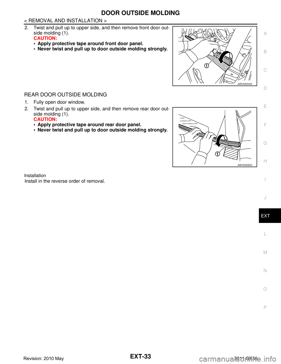
Exploded ViewINFOID:0000000006367617
Removal and InstallationINFOID:0000000006367618
FRONT DOOR OUTSIDE MOLDING
Removal
1. Fully open door window.
1. Front door panel 2. Front door outside molding 3. Rear door outside molding
4. Rear door panel: Pawl
JMKIA5372ZZ
Revision: 2010 May2011 QX56
Page 2888 of 5598

DOOR OUTSIDE MOLDINGEXT-33
< REMOVAL AND INSTALLATION >
C
DE
F
G H
I
J
L
M A
B
EXT
N
O P
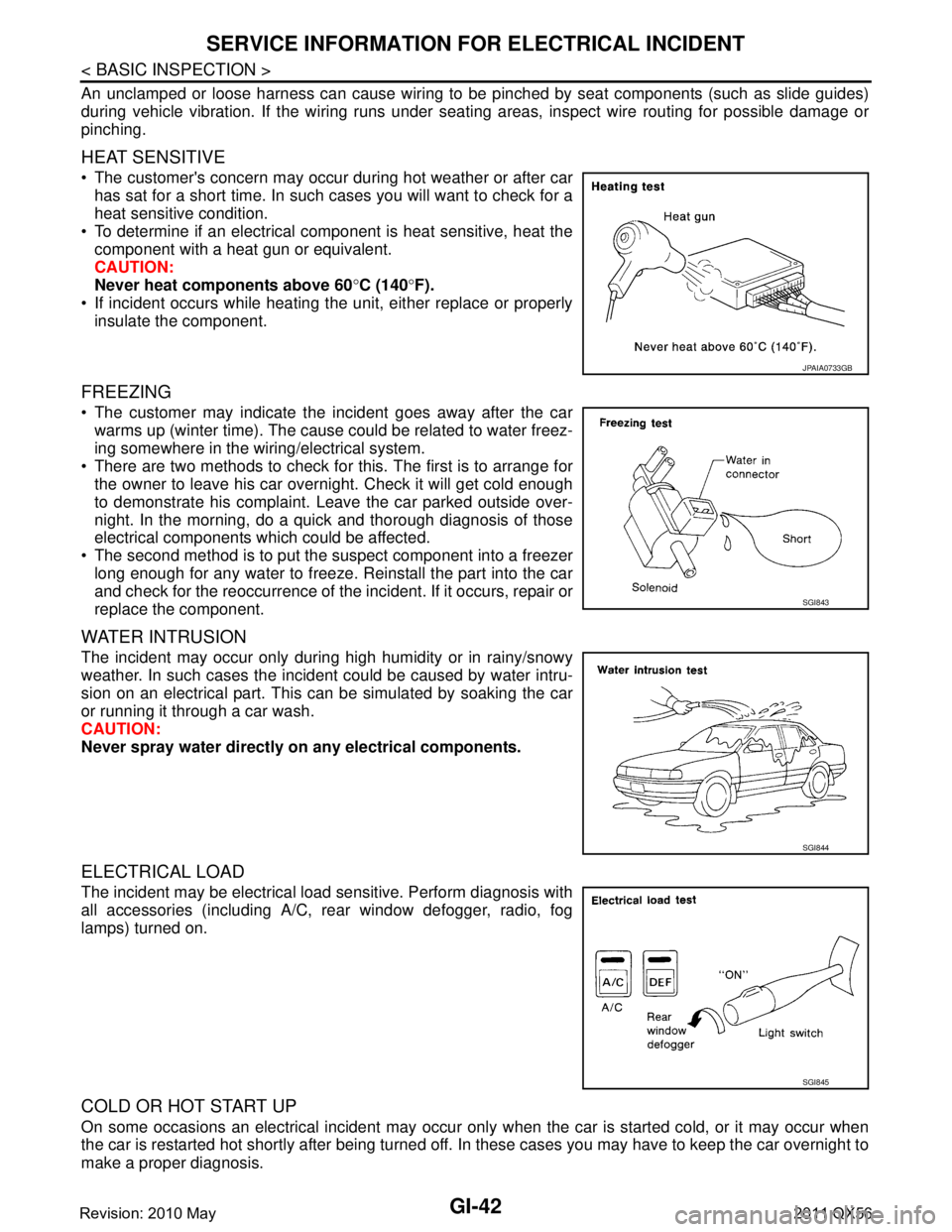
2. Twist and pull up to upper side, and then remove front door out- side molding (1).
CAUTION:
Apply protective tape around front door panel.
Never twist and pull up to do or outside molding strongly.
REAR DOOR OUTSIDE MOLDING
1. Fully open door window.
2. Twist and pull up to upper side, and then remove rear door out-
side molding (1).
CAUTION:
Apply protective tape around rear door panel.
Never twist and pull up to do or outside molding strongly.
Installation
Install in the reverse order of removal.
JMKIA2024ZZ
JMKIA2026ZZ
Revision: 2010 May2011 QX56
Page 2986 of 5598

GI-22
< HOW TO USE THIS MANUAL >
RECOMMENDED CHEMICAL PRODUCTS AND SEALANTS
RECOMMENDED CHEMICAL PRODUCTS AND SEALANTS
Recommended Chemical Products and SealantsINFOID:0000000006280850
Refer to the following chart for help in selecting the appropriate chemical product or sealant.
Product Description Purpose Nissan North America
Part No. (USA) Nissan Canada Part
No. (Canada) Aftermarket Cross-
reference Part Nos.
1 Rear View Mirror Adhe-
sive Used to permanently re-
mount rear view mirrors to
windows.
999MP-AM000P 99998-50505 Permatex 81844
2 Anaerobic Liquid Gas-
ket For metal-to-metal flange
sealing.
Can fill a 0.38 mm (0.015
inch) gap and provide in-
stant sealing for most pow-
ertrain applications.
999MP-AM001P 99998-50503
Permatex 51813 and
51817
3 High Performance
Thread Sealant Provides instant sealing on
any threaded straight or
parallel threaded fitting.
(Thread sealant only, no
locking ability.)
Do not use on plastic.
999MP-AM002P 999MP-AM002P Permatex 56521
4 Silicone RTV Gasket Maker
999MP-AM003P
(Ultra Grey)99998-50506
(Ultra Grey)Permatex Ultra Grey
82194;
Three Bond
1207,1215, 1216,
1217F, 1217G and
1217H
Nissan RTV Part No.
999MP-A7007
Gasket Maker for Maxima/
Quest 5-speed automatic
transmission
(RE5F22A) ––
Three Bond 1281B
or exact equivalent in
its quality
5 High Temperature,
High Strength Thread
Locking Sealant (Red)
Threadlocker 999MP-AM004P 999MP-AM004P Permatex 27200;
Three Bond 1360,
1360N, 1305 N&P,
1307N, 1335,
1335B, 1363B,
1377C, 1386B, D&E
and 1388
Loctite 648
6 Medium Strength
Thread Locking Seal-
ant (Blue) Threadlocker (service tool
removable)
999MP-AM005P 999MP-AM005P Permatex 24200,
24206, 24240,
24283 and 09178;
Three Bond 1322,
1322N, 1324 D&N,
1333D, 1361C,
1364D, 1370C and
1374
Revision: 2010 May2011 QX56
Page 3006 of 5598

GI-42
< BASIC INSPECTION >
SERVICE INFORMATION FOR ELECTRICAL INCIDENT
An unclamped or loose harness can cause wiring to be pinched by seat components (such as slide guides)
during vehicle vibration. If the wiring runs under s eating areas, inspect wire routing for possible damage or
pinching.
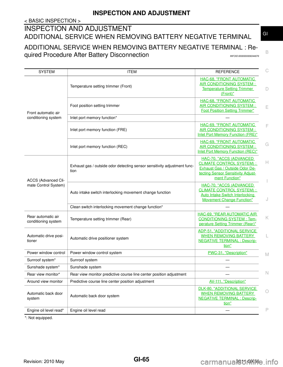
HEAT SENSITIVE
The customer's concern may occur during hot weather or after car has sat for a short time. In such cases you will want to check for a
heat sensitive condition.
To determine if an electrical component is heat sensitive, heat the component with a heat gun or equivalent.
CAUTION:
Never heat components above 60 °C (140 °F).
If incident occurs while heating the unit, either replace or properly insulate the component.
FREEZING
The customer may indicate the incident goes away after the carwarms up (winter time). The cause could be related to water freez-
ing somewhere in the wiring/electrical system.
There are two methods to check for this. The first is to arrange for the owner to leave his car overnight. Check it will get cold enough
to demonstrate his complaint. Leave the car parked outside over-
night. In the morning, do a quick and thorough diagnosis of those
electrical components which could be affected.
The second method is to put the suspect component into a freezer long enough for any water to freeze. Reinstall the part into the car
and check for the reoccurrence of the incident. If it occurs, repair or
replace the component.
WATER INTRUSION
The incident may occur only during high humidity or in rainy/snowy
weather. In such cases the incident could be caused by water intru-
sion on an electrical part. This can be simulated by soaking the car
or running it through a car wash.
CAUTION:
Never spray water directly on any electrical components.
ELECTRICAL LOAD
The incident may be electrical load sensitive. Perform diagnosis with
all accessories (including A/C, rear window defogger, radio, fog
lamps) turned on.
COLD OR HOT START UP
On some occasions an electrical incident may occur only when the car is started cold, or it may occur when
the car is restarted hot shortly after being turned off. In these cases you may have to keep the car overnight to
make a proper diagnosis.
JPAIA0733GB
SGI843
SGI844
SGI845
Revision: 2010 May2011 QX56
Page 3029 of 5598

INSPECTION AND ADJUSTMENTGI-65
< BASIC INSPECTION >
C
DE
F
G H
I
J
K L
M B
GI
N
O PINSPECTION AND ADJUSTMENT
ADDITIONAL SERVICE WHEN REMOVING BATTERY NEGATIVE TERMINAL
ADDITIONAL SERVICE WHEN REMOVING BATTERY NEGATIVE TERMINAL : Re-
quired Procedure After Battery Disconnection
INFOID:0000000006344676
*: Not equipped. SYSTEM ITEM REFERENCE
Front automatic air
conditioning system Temperature setting trimmer (Front)
HAC-68, "
FRONT AUTOMATIC
AIR CONDITIONING SYSTEM :
Temperature Setting Trimmer
(Front)"
Foot position setting trimmer
HAC-68, "
FRONT AUTOMATIC
AIR CONDITIONING SYSTEM :
Foot Position Setting Trimmer"
Inlet port memory function* —
Inlet port memory function (FRE)
HAC-69, "
FRONT AUTOMATIC
AIR CONDITIONING SYSTEM :
Inlet Port Memory
Function (FRE)"
Inlet port memory function (REC) HAC-69, "
FRONT AUTOMATIC
AIR CONDITIONING SYSTEM :
Inlet Port Memory Function (REC)"
ACCS (Advanced Cli-
mate Control System)Exhaust gas / outside odor detecting sensor sensitivity adjustment func-
tion
HAC-70, "
ACCS (ADVANCED
CLIMATE CONTROL SYSTEM) :
Exhaust Gas / Outside Odor De-
tecting Sensor Sensitivity Adjust-
ment Function"
Auto intake switch interlocking movement change function
HAC-70, "
ACCS (ADVANCED
CLIMATE CONTROL SYSTEM) :
Auto Intake Switch Interlocking
Movement Change Function"
Clean switch interlocking movement change function* —
Rear automatic air
conditioning system Temperature setting trimmer (Rear) HAC-69, "
REAR AUTOMATIC AIR
CONDITIONING SYSTEM : Tem-
perature Setting
Trimmer (Rear)"
Automatic drive posi-
tioner Automatic drive positioner system ADP-51, "
ADDITIONAL SERVICE
WHEN REMOVING BATTERY
NEGATIVE TERMINAL : Descrip-
tion"
Power window control Power window control system
PWC-31, "Description"
Sunroof system* Sunroof system —
Sunshade system* Sunshade system —
Rear view monitor* Rear view monitor predictive course line center position adjustment —
Around view monitor Predictive course line center position adjustment AV- 111 , "
Description"
Automatic back door
systemAutomatic back door system DLK-80, "
ADDITIONAL SERVICE
WHEN REMOVING BATTERY
NEGATIVE TERMINAL : Descrip-
tion"
Engine oil level read* Engine oil level read —
Revision: 2010 May2011 QX56