Page 1526 of 5598
DEF-34
< DTC/CIRCUIT DIAGNOSIS >
WIPER DEICER
WIPER DEICER
Component Function CheckINFOID:0000000006299454
1.CHECK WIPER DEICER
1. Select Active Test (“REAR DEFOGGER”) mode of “BCM” using CONSULT-III.
2. Touch “ON”.
3. Check that the front window heating wire is getting warmer.
Is the inspection result normal?
YES >> Wiper deicer is OK.
NO >> Refer to DEF-34, "
Diagnosis Procedure"
Diagnosis ProcedureINFOID:0000000006299455
1.CHECK FUSE
1. Turn ignition switch OFF.
2. Check 15 A fuse [No.75, located in fuse block (J/B)]
Is the inspection result normal?
YES >> GO TO 2.
NO >> Replace the blown fuse after repairing the affected circuit if a fuse is blown.
2.CHECK POWER SUPPLY CIRCUIT
1. Turn ignition switch ON.
2. Check voltage between wiper deicer harness connector and ground.
Is the inspection result normal?
YES >> GO TO 3.
NO >> GO TO 4.
3.CHECK GROUND CIRCUIT
1. Turn ignition switch OFF.
2. Disconnect wiper deicer connector.
3. Check continuity between wiper deicer harness connector and ground.
Is the inspection result normal?
YES >> GO TO 5.
NO >> Repair or replace harness between rear window defogger and ground.
4.CHECK WIPER DEICER CIRCUIT
1. Turn ignition switch OFF.
2. Disconnect wiper deicer relay connector and wiper deicer connector.
3. Check continuity between wiper deicer relay harness connector and wiper deicer harness connector.
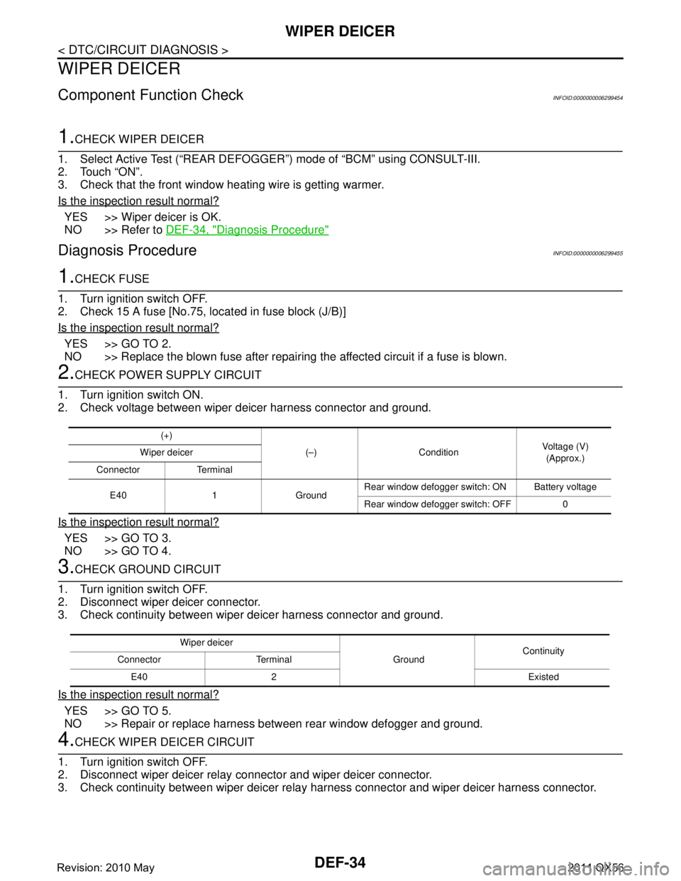
(+)
(–) Condition Voltage (V)
(Approx.)
Wiper deicer
Connector Terminal
E40 1 Ground Rear window defogger switch: ON Battery voltage
Rear window defogger switch: OFF 0
Wiper deicer
GroundContinuity
Connector Terminal
E40 2 Existed
Revision: 2010 May2011 QX56
Page 1528 of 5598
DEF-36
< SYMPTOM DIAGNOSIS >
REAR WINDOW DEFOGGER DOES NOT OPERATE
SYMPTOM DIAGNOSIS
REAR WINDOW DEFOGGER DOES NOT OPERATE
Diagnosis ProcedureINFOID:0000000006299456
1.CHECK REAR WINDOW DEFOGGER SWITCH
Check rear window defogger switch.
Refer to DEF-25, "
Component Function Check".
Is the inspection result normal?
YES >> GO TO 2.
NO >> Repair or replace the malfunctioning parts.
2.CHECK REAR WINDOW DEFOGGER RELAY
Check rear window defogger relay.
Refer to DEF-26, "
Component Function Check".
Is the inspection result normal?
YES >> GO TO 3.
NO >> Repair or replace the malfunctioning parts.
3.CHECK REAR WINDOW DEFOGGER
Check rear window defogger.
Refer to DEF-27, "
Component Function Check".
Is the inspection result normal?
YES >> GO TO 4.
NO >> Repair or replace the malfunctioning parts.
4.CONFIRM THE OPERATION
Confirm the operation again.
Is the inspection result normal?
YES >> Check intermittent incident. Refer to GI-40, "Intermittent Incident".
NO >> GO TO 1.
Revision: 2010 May2011 QX56
Page 1529 of 5598
REAR WINDOW DEFOGGER AND DOOR MIRROR DEFOGGER DO NOT OPER-
ATE.
DEF-37
< SYMPTOM DIAGNOSIS >
C
D E
F
G H
I
J
K
M A
B
DEF
N
O P
REAR WINDOW DEFOGGER AND DO OR MIRROR DEFOGGER DO NOT
OPERATE.
Diagnosis ProcedureINFOID:0000000006299457
1.CHECK REAR WINDOW DEFOGGER SWITCH
Check rear window defogger switch.
Refer to DEF-25, "
Component Function Check".
Is the inspection result normal?
YES >> GO TO 2.
NO >> Repair or replace the malfunctioning parts.
2.CHECK REAR WINDOW DEFOGGER RELAY
Check rear window defogger relay.
Refer to DEF-26, "
Component Function Check".
Is the inspection result normal?
YES >> GO TO 3.
NO >> Repair or replace the malfunctioning parts.
3.CHECK REAR WINDOW DEFOGGER
Check rear window defogger.
Refer to DEF-27, "
Component Function Check".
Is the inspection result normal?
YES >> GO TO 4.
NO >> Repair or replace the malfunctioning parts.
4.CONFIRM THE OPERATION
Confirm the operation again.
Is the inspection result normal?
YES >> Check intermittent incident. Refer to GI-40, "Intermittent Incident".
NO >> GO TO 1.
Revision: 2010 May2011 QX56
Page 1530 of 5598
DEF-38
< SYMPTOM DIAGNOSIS >
REAR WINDOW DEFOGGER DOES NOT OPERATE BUT BOTH DOOR MIRROR
DEFOGGERS OPERATE.
REAR WINDOW DEFOGGER DOES NOT OPERATE BUT BOTH DOOR
MIRROR DEFOGGERS OPERATE.
Diagnosis ProcedureINFOID:0000000006299458
1.CHECK REAR WINDOW DEFOGGER
Check rear window defogger.
Refer to DEF-27, "
Component Function Check".
Is the inspection result normal?
YES >> GO TO 2.
NO >> Repair or replace the malfunctioning parts.
2.CONFIRM THE OPERATION
Confirm the operation again
Is the inspection result normal?
YES >> Check intermittent incident. Refer to GI-40, "Intermittent Incident".
NO >> GO TO 1.
Revision: 2010 May2011 QX56
Page 1534 of 5598
DEF-42
< SYMPTOM DIAGNOSIS >
ON IS NOT DISPLAYED WHEN PRESSING REAR WINDOW DEFOGGER
SWITCH BUT IT IS OPERATED
ON IS NOT DISPLAYED WHEN PR ESSING REAR WINDOW DEFOGGER
SWITCH BUT IT IS OPERATED
Diagnosis ProcedureINFOID:0000000006299466
1.CHECK AV CONTROL UNIT FUNCTION
Check that the AV control unit is operating normally.
Refer to AV-104, "
Work Flow (Multi AV)".
Is the inspection result normal?
YES >> GO TO 2.
NO >> Repair or replace the malfunctioning parts.
2.CONFIRM THE OPERATION
Confirm the operation again.
Is the inspection result normal?
YES >> Check intermittent incident. Refer to GI-40, "Intermittent Incident".
NO >> GO TO 1.
Revision: 2010 May2011 QX56
Page 1548 of 5598
DLK-12
< SYSTEM DESCRIPTION >
COMPONENT PARTS
DOOR LOCK SYSTEM : Component Description
INFOID:0000000006225834
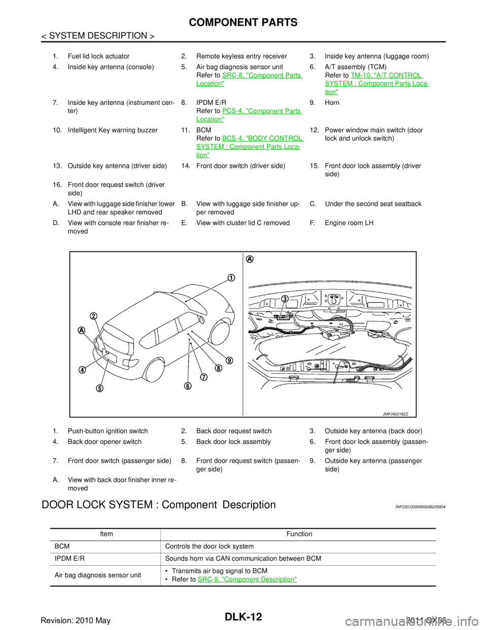
1. Fuel lid lock actuator 2. Remote keyless entry receiver 3. Inside key antenna (luggage room)
4. Inside key antenna (console) 5. Air bag diagnosis sensor unit Refer to SRC-8, "
Component Parts
Location"
6. A/T assembly (TCM)
Refer to TM-10, "
A/T CONTROL
SYSTEM : Component Parts Loca-
tion"
7. Inside key antenna (instrument cen-
ter) 8. IPDM E/R
Refer to PCS-4, "
Component Parts
Location"
9. Horn
10. Intelligent Key warning buzzer 11. BCM Refer to BCS-4, "
BODY CONTROL
SYSTEM : Component Parts Loca-
tion"
12. Power window main switch (door
lock and unlock switch)
13. Outside key antenna (driver side) 14. Front door switch (driver side) 15. Front door lock assembly (driver side)
16. Front door request switch (driver side)
A. View with luggage side finisher lower LHD and rear speaker removed B. View with luggage side finisher up-
per removed C. Under the second seat seatback
D. View with console rear finisher re- moved E. View with cluster lid C removed F. Engine room LH
1. Push-button ignition switch 2. Back door request switch 3. Outside key antenna (back door)
4. Back door opener switch 5. Back door lock assembly 6. Front door lock assembly (passen- ger side)
7. Front door switch (passenger side) 8. Front door request switch (passen- ger side)9. Outside key antenna (passenger
side)
A. View with back door finisher inner re- moved
JMKIA5218ZZ
Item Function
BCM Controls the door lock system
IPDM E/R Sounds horn via CAN communication between BCM
Air bag diagnosis sensor unit Transmits air bag signal to BCM
Refer to
SRC-9, "
Component Description"
Revision: 2010 May2011 QX56
Page 1549 of 5598
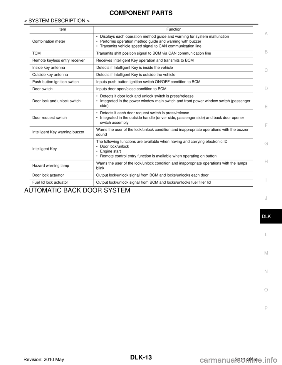
COMPONENT PARTSDLK-13
< SYSTEM DESCRIPTION >
C
DE
F
G H
I
J
L
M A
B
DLK
N
O P
AUTOMATIC BACK DOOR SYSTEM
Combination meter Displays each operation method guide and warning for system malfunction
Performs operation method guide and warning with buzzer
Transmits vehicle speed signal to CAN communication line
TCM Transmits shift position signal to BCM via CAN communication line
Remote keyless entry receiver Receives Intelligent Key operation and transmits to BCM
Inside key antenna Detects if Intelligent Key is inside the vehicle
Outside key antenna Detects if Intelligent Key is outside the vehicle
Push-button ignition switch Inputs push-button ignition switch ON/OFF condition to BCM
Door switch Inputs door open/close condition to BCM
Door lock and unlock switch Detects if door lock and unlock switch is press/release
Integrated in the power window main switch and front power window switch (passenger
side)
Door request switch Detects if each door request switch is press/release
Integrated in the outside handle (driver side, passenger side) and back door opener
switch assembly
Intelligent Key warning buzzer Warns the user of the lock/unlock condition and inappropriate operations with the buzzer
sound
Intelligent Key The following functions are available when having and carrying electronic ID
Door lock/unlock
Engine start
Remote control entry function is available when operating on button
Hazard warning lamp Warns the user of the lock/unlock condition and inappropriate operations with the lamps
blink
Door lock actuator Output lock/unlock signal from BCM and locks/unlocks each door
Fuel lid lock actuator Output lock/unlock signal from BCM and locks/unlocks fuel filler lid Item Function
Revision: 2010 May2011 QX56
Page 1552 of 5598
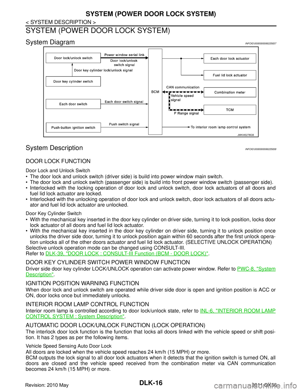
DLK-16
< SYSTEM DESCRIPTION >
SYSTEM (POWER DOOR LOCK SYSTEM)
SYSTEM (POWER DOOR LOCK SYSTEM)
System DiagramINFOID:0000000006225837
System DescriptionINFOID:0000000006225838
DOOR LOCK FUNCTION
Door Lock and Unlock Switch
The door lock and unlock switch (driver side) is build into power window main switch.
The door lock and unlock switch (passenger side) is build into front power window switch (passenger side).
Interlocked with the locking operation of door lock and unlock switch, door lock actuators of all doors and
fuel lid lock actuator are locked.
Interlocked with the unlocking operation of door lock and unlock switch, door lock actuators of all doors actu-
ator and fuel lid lock actuator are unlocked.
Door Key Cylinder Switch
With the mechanical key inserted in the door key cylinder on driver side, turning it to lock position, locks door
lock actuator of all doors and fuel lid lock actuator.
With the mechanical key inserted in the door key cylinder on driver side, turning it to unlock position once
unlocks the driver side door, turning it to unlock posit ion again within 60 seconds after the first unlock opera-
tion unlocks all of the other doors actuator and fuel lid lock actuator. (SELECTIVE UNLOCK OPERATION)
Selective unlock operation mode can be changed using CONSULT-III.
Refer to DLK-39, "
DOOR LOCK : CONSULT-III Function (BCM - DOOR LOCK)".
DOOR KEY CYLINDER SWITCH POWER WINDOW FUNCTION
Driver side door key cylinder LOCK/UNLOCK oper ation can activate power window. Refer to PWC-8, "System
Description".
IGNITION POSITION WARNING FUNCTION
When door lock and unlock switch are operated while dr iver side door is open and ignition position is ACC or
ON, door locks once but immediately unlocks.
INTERIOR ROOM LAMP CONTROL FUNCTION
Interior room lamp is controlled according to door lock/unlock state, refer to INL-6, "INTERIOR ROOM LAMP
CONTROL SYSTEM : System Description".
AUTOMATIC DOOR LOCK/UNLOCK FUNCTION (LOCK OPERATION)
The interlock door lock function is the function that locks all doors linked with the vehicle speed or shift posi-
tion. It has 2 types as per the following items.
Vehicle Speed Sensing Auto Door Lock
All doors are locked when the vehicle speed reaches 24 km/h (15 MPH) or more.
BCM outputs the lock signal to all door lock actuators when it detects that the ignition switch is turned ON, all
doors are closed and the vehicle speed received from the combination meter via CAN communication
becomes 24 km/h (15 MPH) or more.
JMKIA5278GB
Revision: 2010 May2011 QX56