2011 INFINITI QX56 ground
[x] Cancel search: groundPage 3745 of 5598

MWI-2
DIAGNOSIS SYSTEM (COMBINATION
METER) ..............................................................
29
On Board Diagnosis Function .............................. ...29
CONSULT-III Function ...........................................30
ECU DIAGNOSIS INFORMATION ..............35
COMBINATION METER ................................. ...35
Reference Value .................................................. ...35
Fail-Safe .................................................................42
DTC Index ..............................................................43
IPDM E/R ...........................................................44
List of ECU Reference ......................................... ...44
WIRING DIAGRAM .....................................45
METER SYSTEM ............................................ ...45
Wiring Diagram .................................................... ...45
CLOCK ...............................................................55
Wiring Diagram .................................................... ...55
BASIC INSPECTION ...................................57
DIAGNOSIS AND REPAIR WORKFLOW
(METER SYSTEM ) .......................................... ...
57
Work flow ............................................................. ...57
DTC/CIRCUIT DIAGNOSIS ...................... ...59
U1000 CAN COMM CIRCUIT ......................... ...59
Description ........................................................... ...59
DTC Logic ...............................................................59
Diagnosis Procedure .............................................59
U1010 CONTROL UNIT (CAN) .........................60
Description ........................................................... ...60
DTC Logic ...............................................................60
Diagnosis Procedure ..............................................60
B2205 VEHICLE SPEED ...................................61
Description ........................................................... ...61
DTC Logic ...............................................................61
Diagnosis Procedure .............................................61
B2267 ENGINE SPEED .....................................62
Description ........................................................... ...62
DTC Logic ...............................................................62
Diagnosis Procedure ..............................................62
B2268 WATER TEMP ........................................63
Description ........................................................... ...63
DTC Logic ...............................................................63
Diagnosis Procedure ..............................................63
POWER SUPPLY AND GROUND CIRCUIT .....64
COMBINATION METER ........................................ ...64
COMBINATION METER : Diagnosis Procedure ....64
TRIP RESET AND ILLUMINATION CON-
TROL SWITCH SIGNAL CIRCUIT ....................
65
Diagnosis Procedure ............................................ ...65
Component Inspection ............................................66
TRIP COMPUTER SWITCH SIGNAL CIRCUIT
...
67
Diagnosis Procedure ............................................ ...67
Component Inspection ............................................68
FUEL LEVEL SENSOR SIGNAL CIRCUIT .......69
Component Function Check ................................ ...69
Diagnosis Procedure ..............................................69
Component Inspection ............................................70
OIL PRESSURE SWITCH SIGNAL CIRCUIT ...71
Component Function Check ...................................71
Diagnosis Procedure ...............................................71
Component Inspection ............................................71
WASHER LEVEL SWITCH SIGNAL CIRCUIT ...73
Diagnosis Procedure ............................................ ...73
Component Inspection ............................................73
A/C AUTO AMP. CONNECTION RECOGNI-
TION SIGNAL CIRCUIT ....................................
74
Diagnosis Procedure ........................................... ...74
SYMPTOM DIAGNOSIS ............................75
THE FUEL GAUGE INDICATOR DOES NOT
OPERATE ....................................................... ...
75
Description ........................................................... ...75
Diagnosis Procedure ...............................................75
THE TRIP RESET AND ILLUMINATION CON-
TROL SWITCH IS INOPERATIVE ....................
76
Description ........................................................... ...76
Diagnosis Procedure ...............................................76
THE TRIP COMPUTER SWITCH IS INOPER-
ATIVE .................................................................
77
Description ........................................................... ...77
Diagnosis Procedure ...............................................77
THE OIL PRESSURE WARNING LAMP
DOES NOT TURN ON .................................... ...
78
Description ........................................................... ...78
Diagnosis Procedure ...............................................78
THE OIL PRESSURE WARNING LAMP
DOES NOT TURN OFF .................................. ...
79
Description ........................................................... ...79
Diagnosis Procedure ...............................................79
THE PARKING BRAKE RELEASE WARNING
CONTINUES DISPLAYING, OR DOES NOT
DISPLAY ............................................................
80
Description ........................................................... ...80
Diagnosis Procedure ...............................................80
Revision: 2010 May2011 QX56
Page 3772 of 5598
MWI
DIAGNOSIS SYSTEM (COMBINATION METER)
MWI-29
< SYSTEM DESCRIPTION >
C
D E
F
G H
I
J
K L
M B A
O P
DIAGNOSIS SYSTEM (COMBINATION METER)
On Board Diagnosis FunctionINFOID:0000000006221719
ON BOARD DIAGNOSIS ITEM
The combination meter allows the following diagnosis items with the on-board diagnosis function.
METHOD OF STARTING
1. Turn ignition switch OFF.
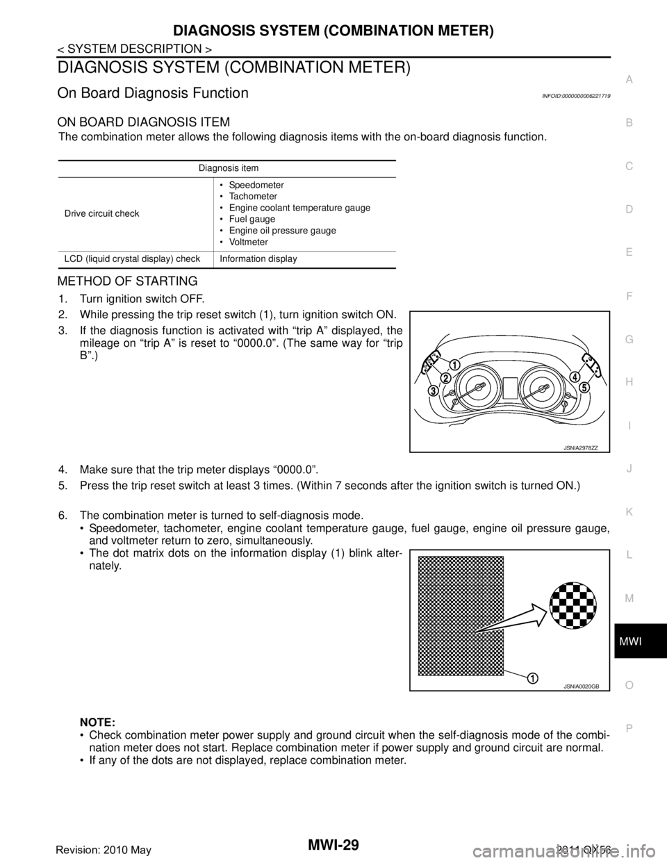
2. While pressing the trip reset switch (1), turn ignition switch ON.
3. If the diagnosis function is activated with “trip A” displayed, the
mileage on “trip A” is reset to “0000.0”. (The same way for “trip
B”.)
4. Make sure that the trip meter displays “0000.0”.
5. Press the trip reset switch at least 3 times. (Wit hin 7 seconds after the ignition switch is turned ON.)
6. The combination meter is turned to self-diagnosis mode. Speedometer, tachometer, engine coolant temper ature gauge, fuel gauge, engine oil pressure gauge,
and voltmeter return to zero, simultaneously.
The dot matrix dots on the information display (1) blink alter-
nately.
NOTE:
Check combination meter power supply and ground circuit when the self-diagnosis mode of the combi- nation meter does not start. Replace combination meter if power supply and ground circuit are normal.
If any of the dots are not displayed, replace combination meter.
Diagnosis item
Drive circuit check Speedometer
Tachometer
Engine coolant temperature gauge
Fuel gauge
Engine oil pressure gauge
Voltmeter
LCD (liquid crystal display) check Information display
JSNIA2978ZZ
JSNIA0020GB
Revision: 2010 May2011 QX56
Page 3782 of 5598
MWI
COMBINATION METERMWI-39
< ECU DIAGNOSIS INFORMATION >
C
DE
F
G H
I
J
K L
M B A
O P
NOTE:
Some items are not available according to vehicle specification.
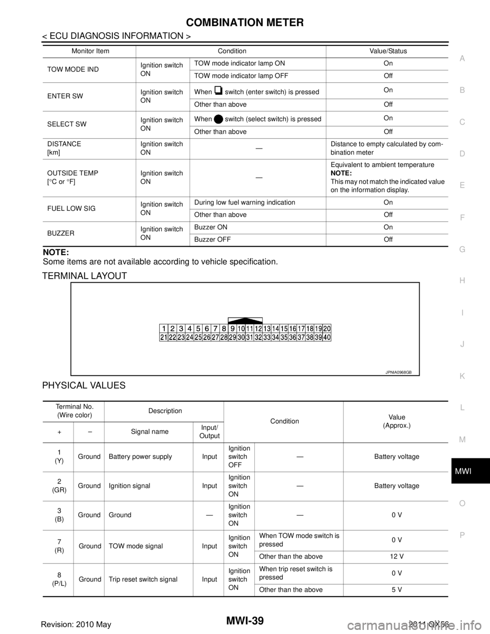
TERMINAL LAYOUT
PHYSICAL VALUES
TOW MODE IND Ignition switch
ONTOW mode indicator lamp ON On
TOW mode indicator lamp OFF Off
ENTER SW Ignition switch
ONWhen switch (enter switch) is pressed
On
Other than above Off
SELECT SW Ignition switch
ONWhen switch (select switch) is pressed
On
Other than above Off
DISTANCE
[km] Ignition switch
ON
—Distance to empty calculated by com-
bination meter
OUTSIDE TEMP
[ ° C or °F] Ignition switch
ON
—Equivalent to ambient temperature
NOTE:
This may not match the indicated value
on the information display.
FUEL LOW SIG Ignition switch
ONDuring low fuel warning indication On
Other than above Off
BUZZER Ignition switch
ONBuzzer ON On
Buzzer OFF Off
Monitor Item Condition Value/Status
JPNIA0968GB
Te r m i n a l N o .
(Wire color) Description
ConditionVa l u e
(Approx.)
+ – Signal name Input/
Output
1
(Y) Ground Battery power supply Input Ignition
switch
OFF— Battery voltage
2
(GR) Ground Ignition signal Input Ignition
switch
ON
— Battery voltage
3
(B) Ground Ground — Ignition
switch
ON—0 V
7
(R) Ground TOW mode signal Input Ignition
switch
ONWhen TOW mode switch is
pressed
0 V
Other than the above 12 V
8
(P/L) Ground Trip reset switch signal Input Ignition
switch
ONWhen trip reset switch is
pressed
0 V
Other than the above 5 V
Revision: 2010 May2011 QX56
Page 3783 of 5598
MWI-40
< ECU DIAGNOSIS INFORMATION >
COMBINATION METER
11
(G) Ground Enter switch signal Input Ignition
switch
ONWhen switch (enter
switch) is pressed
0 V
Other than the above 5 V
12
(O) Ground Select switch signal Input Ignition
switch
ONWhen switch (select
switch) is pressed
0 V
Other than the above 5 V
13
(W/R) Ground
Illumination control switch
signal (+) InputIgnition
switch
ON When switch [illumi-
nation control sw
itch (+)] is
pressed 0 V
Other than the above 5 V
14
(R) Ground Illumination control switch
signal (
−) InputIgnition
switch
ON When switch [illumi-
nation control switch (
−)] is
pressed 0 V
Other than the above 5 V
15
(R/W) Ground Air bag signal Input Ignition
switch
ONAir bag warning lamp
ON
4 V
Air bag warning lamp
OFF 0 V
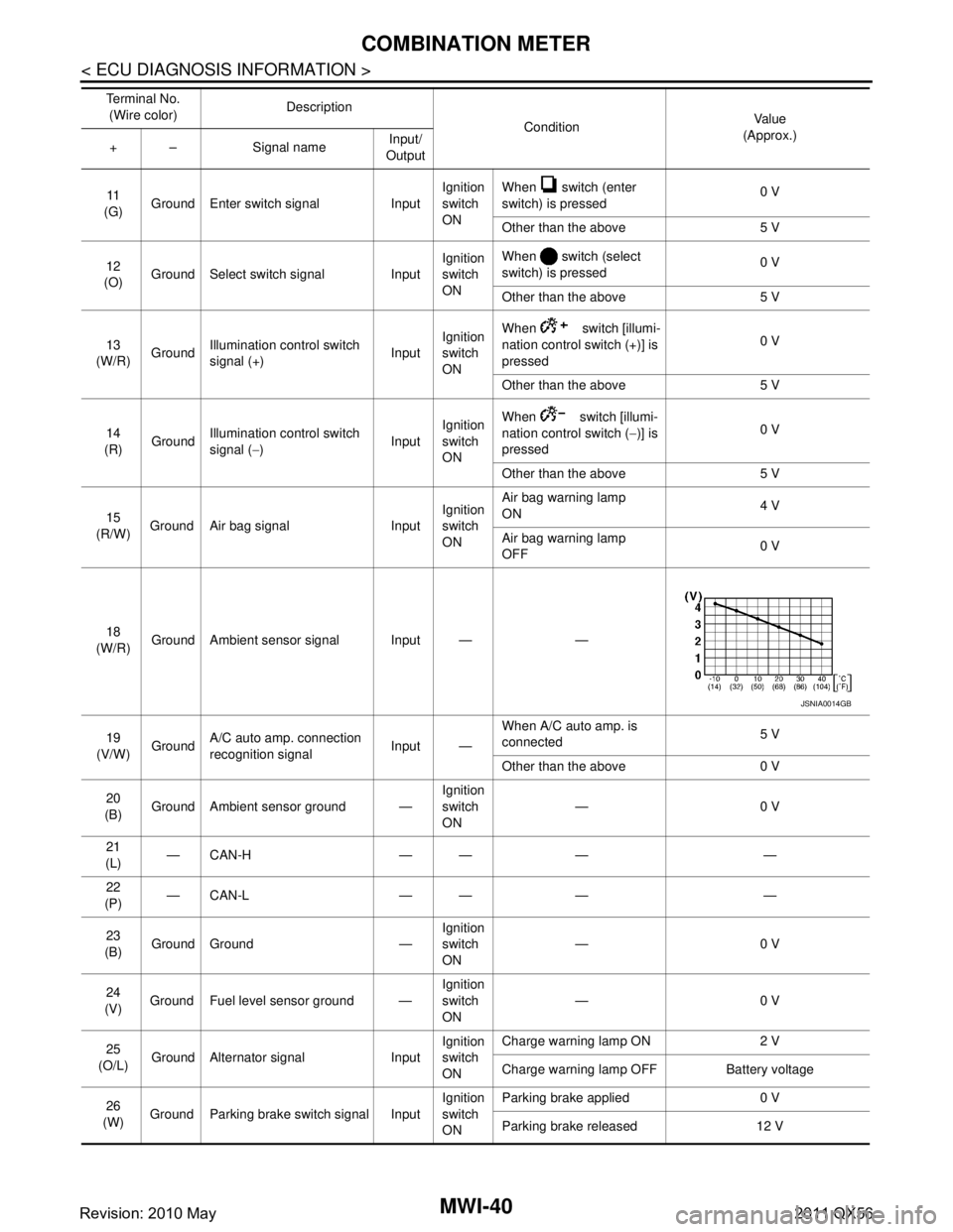
18
(W/R) Ground Ambient sensor signal Input — —
19
(V/W) Ground A/C auto amp. connection
recognition signal Input —When A/C auto amp. is
connected
5 V
Other than the above 0 V
20
(B) Ground Ambient sensor ground — Ignition
switch
ON—0 V
21
(L) —CAN-H — — — —
22
(P) —CAN-L — — — —
23
(B) Ground Ground — Ignition
switch
ON
—0 V
24
(V) Ground Fuel level sensor ground — Ignition
switch
ON—0 V
25
(O/L) Ground Alternator signal Input Ignition
switch
ONCharge warning lamp ON 2 V
Charge warning lamp OFF Battery voltage
26
(W) Ground Parking brake switch signal Input Ignition
switch
ONParking brake applied 0 V
Parking brake released 12 V
Te r m i n a l N o .
(Wire color) Description
ConditionVa l u e
(Approx.)
+ – Signal name Input/
Output
JSNIA0014GB
Revision: 2010 May2011 QX56
Page 3784 of 5598
MWI
COMBINATION METERMWI-41
< ECU DIAGNOSIS INFORMATION >
C
DE
F
G H
I
J
K L
M B A
O P
28
(GR/R) Ground Security signal Input Ignition
switch
ONSecurity indicator lamp ON 0 V
Security indicator lamp
OFF
12 V
29
(BR) Ground Washer level switch signal Input Ignition
switch
ONWasher level switch ON 0 V
Washer level switch OFF 5 V
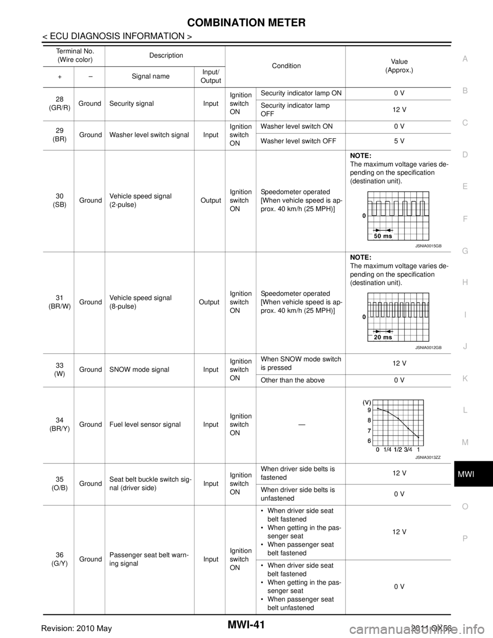
30
(SB) Ground
Vehicle speed signal
(2-pulse) OutputIgnition
switch
ON Speedometer operated
[When vehicle speed is ap-
prox. 40 km/h (25 MPH)] NOTE:
The maximum voltage varies de-
pending on the specification
(destination unit).
31
(BR/W) GroundVehicle speed signal
(8-pulse)
OutputIgnition
switch
ONSpeedometer operated
[When vehicle speed is ap-
prox. 40 km/h (25 MPH)] NOTE:
The maximum voltage varies de-
pending on the specification
(destination unit).
33
(W) Ground SNOW mode signal Input Ignition
switch
ONWhen SNOW mode switch
is pressed
12 V
Other than the above 0 V
34
(BR/Y) Ground Fuel level sensor signal Input Ignition
switch
ON
—
35
(O/B) Ground Seat belt buckle switch sig-
nal (driver side)
InputIgnition
switch
ON When driver side belts is
fastened
12 V
When driver side belts is
unfastened 0 V
36
(G/Y) Ground Passenger seat belt warn-
ing signal
InputIgnition
switch
ON When driver side seat
belt fastened
When getting in the pas- senger seat
When passenger seat belt fastened 12 V
When driver side seat belt fastened
When getting in the pas- senger seat
When passenger seat belt unfastened 0 V
Te r m i n a l N o .
(Wire color) Description
ConditionVa l u e
(Approx.)
+ – Signal name Input/
Output
JSNIA0015GB
JSNIA0012GB
JSNIA3013ZZ
Revision: 2010 May2011 QX56
Page 3785 of 5598

MWI-42
< ECU DIAGNOSIS INFORMATION >
COMBINATION METER
Fail-Safe
INFOID:0000000006221722
FA I L - S A F E
The combination meter activates the fail-safe contro l if CAN communication with each unit is malfunctioning.
37
(R/Y) Ground Non-manual mode signal Input Ignition
switch
ONSelector manual mode po-
sition
12 V
Other than the above 0 V
38
(L/W) Ground Manual mode shift down
signal InputIgnition
switch
ON Selector lever DOWN oper-
ation
0 V
Other than the above 12 V
39
(Y/B) Ground Manual mode shift up sig-
nal InputIgnition
switch
ON Selector lever UP operation 0 V
Other than the above 12 V
40
(G/W) Ground Manual mode signal Input Ignition
switch
ONSelector manual mode po-
sition
0 V
Other than the above 12 V
Te r m i n a l N o .
(Wire color) Description
ConditionVa l u e
(Approx.)
+ – Signal name Input/
Output
Function Specifications
Speedometer
Reset to zero by suspending communication.
Tachometer
Engine coolant temperature gauge
Engine oil pressure gauge
Illumination control When suspending communication, changes to nighttime mode.
Information display Odo/trip meter An indicated value is maintained at communications blackout.
Shift position indicator The display turns OFF by suspending communication.
Door open warning The display turns OFF by suspending communication.
Buzzer The buzzer turns OFF by suspending communication.
Revision: 2010 May2011 QX56
Page 3801 of 5598
MWI-58
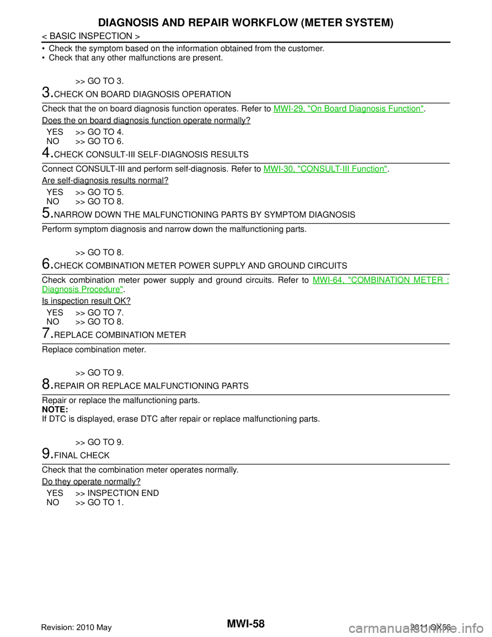
< BASIC INSPECTION >
DIAGNOSIS AND REPAIR WORKFLOW (METER SYSTEM)
Check the symptom based on the inform ation obtained from the customer.
Check that any other malfunctions are present.
>> GO TO 3.
3.CHECK ON BOARD DIAGNOSIS OPERATION
Check that the on board diagnosis function operates. Refer to MWI-29, "
On Board Diagnosis Function".
Does the on board diagnosis function operate normally?
YES >> GO TO 4.
NO >> GO TO 6.
4.CHECK CONSULT-III SELF-DIAGNOSIS RESULTS
Connect CONSULT-III and perform self-diagnosis. Refer to MWI-30, "
CONSULT-III Function".
Are self-diagnosis results normal?
YES >> GO TO 5.
NO >> GO TO 8.
5.NARROW DOWN THE MALFUNCTIONING PARTS BY SYMPTOM DIAGNOSIS
Perform symptom diagnosis and narrow down the malfunctioning parts.
>> GO TO 8.
6.CHECK COMBINATION METER POWE R SUPPLY AND GROUND CIRCUITS
Check combination meter power supply and ground circuits. Refer to MWI-64, "
COMBINATION METER :
Diagnosis Procedure".
Is inspection result OK?
YES >> GO TO 7.
NO >> GO TO 8.
7.REPLACE COMBINATION METER
Replace combination meter.
>> GO TO 9.
8.REPAIR OR REPLACE MALFUNCTIONING PARTS
Repair or replace the malfunctioning parts.
NOTE:
If DTC is displayed, erase DTC after repair or replace malfunctioning parts.
>> GO TO 9.
9.FINAL CHECK
Check that the combination meter operates normally.
Do they operate normally?
YES >> INSPECTION END
NO >> GO TO 1.
Revision: 2010 May2011 QX56
Page 3807 of 5598

MWI-64
< DTC/CIRCUIT DIAGNOSIS >
POWER SUPPLY AND GROUND CIRCUIT
POWER SUPPLY AND GROUND CIRCUIT
COMBINATION METER
COMBINATION METER : Diagnosis ProcedureINFOID:0000000006221743
1.CHECK FUSE
Check for blown fuses.
Is the inspection result normal?
YES >> GO TO 2.
NO >> Be sure to eliminate cause of malfunction before installing new fuse.
2.CHECK POWER SUPPLY CIRCUIT
Check voltage between combination meter harness connector and ground.
Is the inspection result normal?
YES >> GO TO 3.
NO >> Check harness between combination meter and fuse.
3.CHECK GROUND CIRCUIT
1. Turn ignition switch OFF.
2. Disconnect combination meter connector.
3. Check continuity between combination meter harness connector and ground.
Is the inspection result normal?
YES >> INSPECTION END
NO >> Repair harness or connector.
Power source Fuse No.
Battery 11
Ignition switch ON or START 3
Te r m i n a l s
Ignition switch po-sition Vol tag e
(Approx.)
(+) (
−)
Combination meter
Ground
Connector Terminal
M34 1OFF
Battery voltage
2ON
Combination meter
GroundContinuity
Connector Terminal
M34 3
Existed
23
Revision: 2010 May2011 QX56