Page 2582 of 5598

EM-20
< PERIODIC MAINTENANCE >
DRIVE BELTS
PERIODIC MAINTENANCE
DRIVE BELTS
Exploded ViewINFOID:0000000006289524
CheckingINFOID:0000000006289525
WARNING:
Be sure to perform the these steps when engine is stopped.
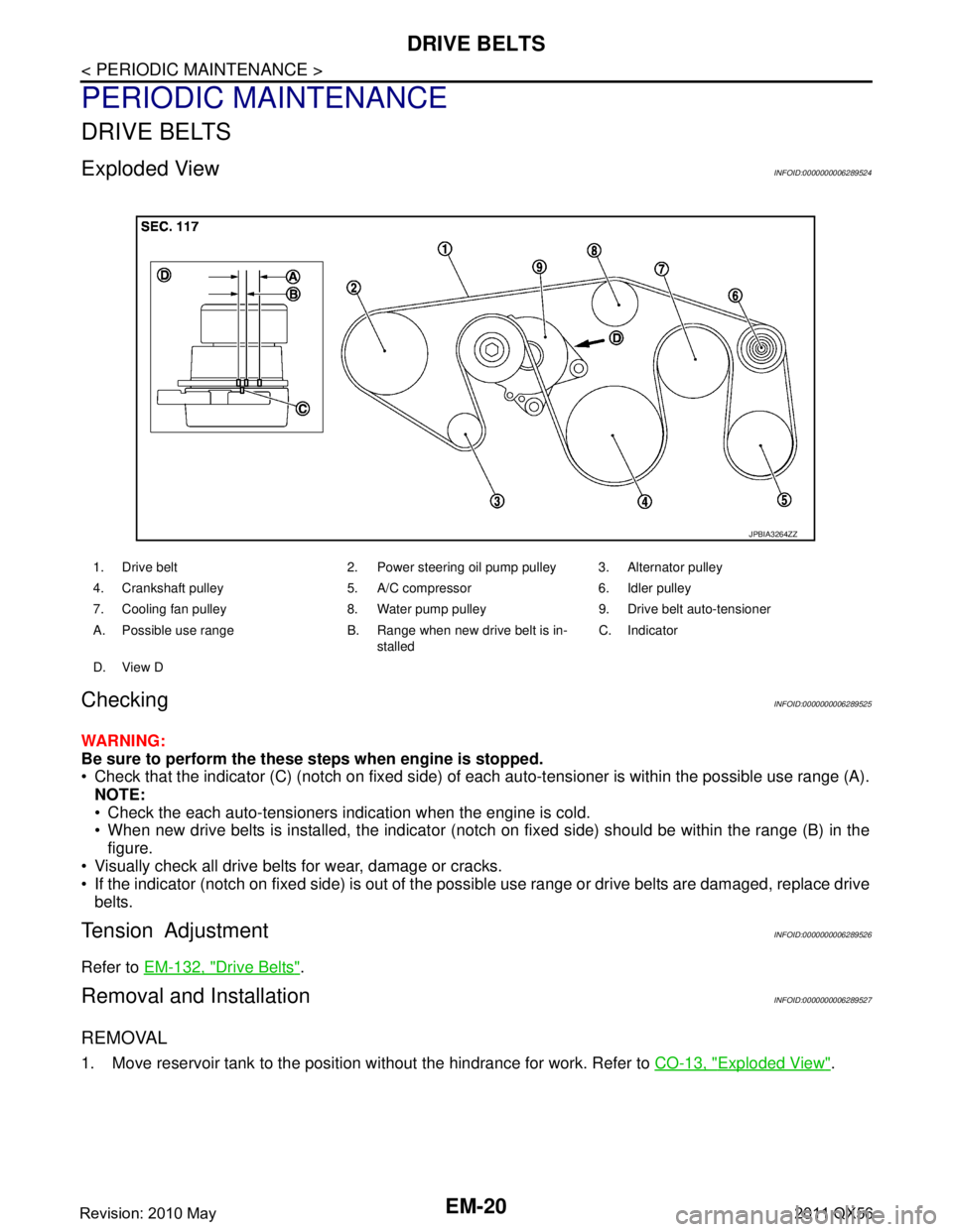
Check that the indicator (C) (notch on fixed side) of each auto-tensioner is within the possible use range (A).
NOTE:
Check the each auto-tensioners indication when the engine is cold.
When new drive belts is installed, the indicator (notch on fixed side) should be within the range (B) in the\
figure.
Visually check all drive belts for wear, damage or cracks.
If the indicator (notch on fixed side) is out of the possible use range or drive belts are damaged, replace drive
belts.
Tension AdjustmentINFOID:0000000006289526
Refer to EM-132, "Drive Belts".
Removal and InstallationINFOID:0000000006289527
REMOVAL
1. Move reservoir tank to the position without the hindrance for work. Refer to CO-13, "Exploded View".
1. Drive belt 2. Power steering oil pump pulley 3. Alternator pulley
4. Crankshaft pulley 5. A/C compressor 6. Idler pulley
7. Cooling fan pulley 8. Water pump pulley 9. Drive belt auto-tensioner
A. Possible use range B. Range when new drive belt is in-
stalledC. Indicator
D. View D
JPBIA3264ZZ
Revision: 2010 May2011 QX56
Page 2583 of 5598

DRIVE BELTSEM-21
< PERIODIC MAINTENANCE >
C
DE
F
G H
I
J
K L
M A
EM
NP
O
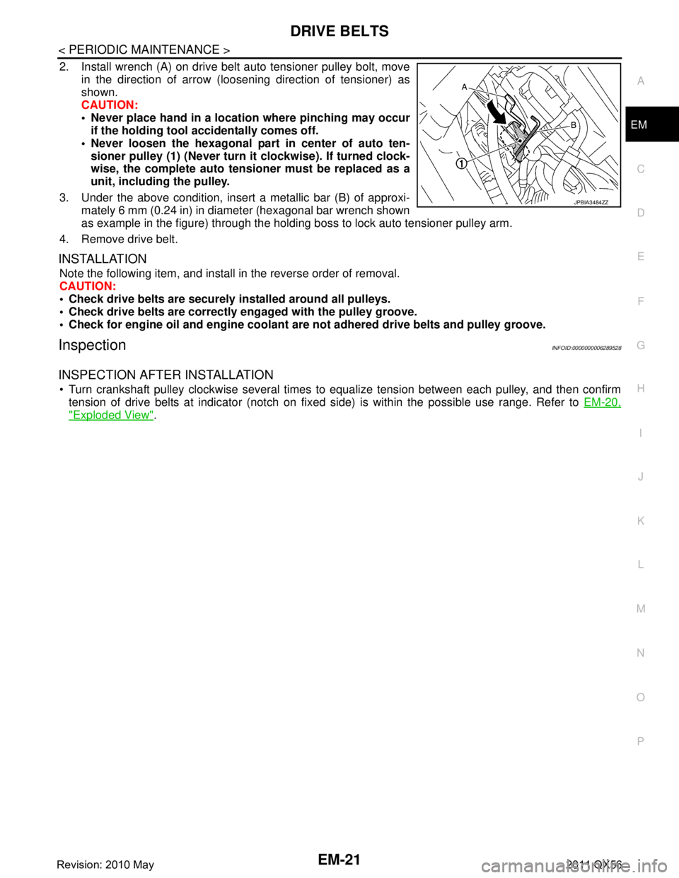
2. Install wrench (A) on drive belt auto tensioner pulley bolt, move
in the direction of arrow (loosening direction of tensioner) as
shown.
CAUTION:
Never place hand in a location where pinching may occurif the holding tool accidentally comes off.
Never loosen the hexagonal part in center of auto ten- sioner pulley (1) (Never turn it clockwise). If turned clock-
wise, the complete auto tensioner must be replaced as a
unit, including the pulley.
3. Under the above condition, insert a metallic bar (B) of approxi- mately 6 mm (0.24 in) in diameter (hexagonal bar wrench shown
as example in the figure) through the holding boss to lock auto tensioner pulley arm.
4. Remove drive belt.
INSTALLATION
Note the following item, and install in the reverse order of removal.
CAUTION:
Check drive belts are securely installed around all pulleys.
Check drive belts are correctly engaged with the pulley groove.
Check for engine oil and engine coolant ar e not adhered drive belts and pulley groove.
InspectionINFOID:0000000006289528
INSPECTION AFTER INSTALLATION
Turn crankshaft pulley clockwise several times to equalize tension between each pulley, and then confirm
tension of drive belts at indicator (notch on fixed side) is within the possible use range. Refer to EM-20,
"Exploded View".
JPBIA3484ZZ
Revision: 2010 May2011 QX56
Page 2585 of 5598
SPARK PLUGEM-23
< PERIODIC MAINTENANCE >
C
DE
F
G H
I
J
K L
M A
EM
NP
O
SPARK PLUG
Exploded ViewINFOID:0000000006289531
Removal and InstallationINFOID:0000000006289532
REMOVAL
1. Remove engine cover. Refer to
EM-25, "Exploded View".
2. Remove ignition coil. Refer to EM-29, "
Exploded View".
3. Remove spark plug with a spark plug wrench (commercial ser- vice tool).
INSTALLATION
Note the following item, installa is the reverse order of removal.
CAUTION:
1. Ignition coil (No. 2, 4) 2. Ignition coil (No. 6, 8) 3. Spark plug
4. Rocker cover (bank 2) 5. Rocker cover (bank 1) 6. Ignition coil (No. 1, 3)
7. Ignition coil (No. 5, 7)
Refer to GI-4, "
Components" for symbols in the figure.
JSBIA0388GB
a : 14 mm (0.55 in)
JPBIA0030ZZ
Revision: 2010 May2011 QX56
Page 2586 of 5598
EM-24
< PERIODIC MAINTENANCE >
SPARK PLUG
Install ignition coil marked with an identification mark (A) on
cylinder No. 5, 6, 7 and 8.
InspectionINFOID:0000000006289533
INSPECTION AFTER REMOVAL
Use the standard type spark plug for normal condition.
CAUTION:
Never drop or impact spark plug.
Never use a wire brush for cleaning.
If plug tip is covered with carbon, use spark plug cleaner to clean.
Measure spark plug gap. When it exceeds the limit, replace spark plug even if it is within the speci-
fied replacement mileage. Refer to EM-132, "
Spark Plug".
Spark plug gap adjustment is not required between replace-
ment intervals.
: Engine front
JPBIA3471ZZ
Spark plug (Standard type) : Refer to EM-132, "Spark Plug".
Cleaner air pressure : Less than 588 kPa (5.9 bar, 6 kg/cm
2, 85 psi)
Cleaning time : Less than 20 seconds
SMA773C
JPBIA0031ZZ
Revision: 2010 May2011 QX56
Page 2591 of 5598
IGNITION COILEM-29
< REMOVAL AND INSTALLATION >
C
DE
F
G H
I
J
K L
M A
EM
NP
O
IGNITION COIL
Exploded ViewINFOID:0000000006289541
Removal and InstallationINFOID:0000000006289542
REMOVAL
1. Remove engine cover. Refer to
EM-25, "Exploded View".
2. Remove ignition coil. CAUTION:
Never impact it.
NOTE:
Installation position of ignition coil depends on cylinder position.
INSTALLATION
1. Install ignition coil.CAUTION:
Install Ignition coil marked with an identification mark (A)
on cylinder No. 5, 6, 7 and 8.
2. Install engine cover.
1. Ignition coil (No. 2, 4) 2. Ignition coil (No. 6, 8) 3. Spark plug
4. Rocker cover (bank 2) 5. Rocker cover (bank 1) 6. Ignition coil (No. 1, 3)
7. Ignition coil (No. 5, 7)
Refer to GI-4, "
Components" for symbols in the figure.
JSBIA0388GB
: Engine front
JPBIA3471ZZ
Revision: 2010 May2011 QX56
Page 2595 of 5598

ROCKER COVEREM-33
< REMOVAL AND INSTALLATION >
C
DE
F
G H
I
J
K L
M A
EM
NP
O
ROCKER COVER
Exploded ViewINFOID:0000000006289545
Removal and InstallationINFOID:0000000006289546
REMOVAL
1. Remove engine cover and bracket (rear). Refer to
EM-25, "Exploded View".
2. Disconnect PCV hose from rocker cover.
3. Remove air cleaner case (upper) and air duct. Refer to EM-27, "
Exploded View".
4. Move the following parts to the position without the hindrance for work. Oil level gauge guide. Refer to EM-57, "
Exploded View".
Power steering fluid reservoir tank bracket. Refer to ST-54, "
Exploded View".
EVAP canister purge control solenoid valve. EM-30, "
Exploded View".
Fuel feed hose. Refer to EM-43, "
Exploded View".
5. Remove VVEL actuator motor assembly. Refer to EM-36, "
Exploded View".
6. Remove ignition coil. Refer to EM-29, "
Exploded View".
CAUTION:
Never impact it.
7. Remove rocker cover.
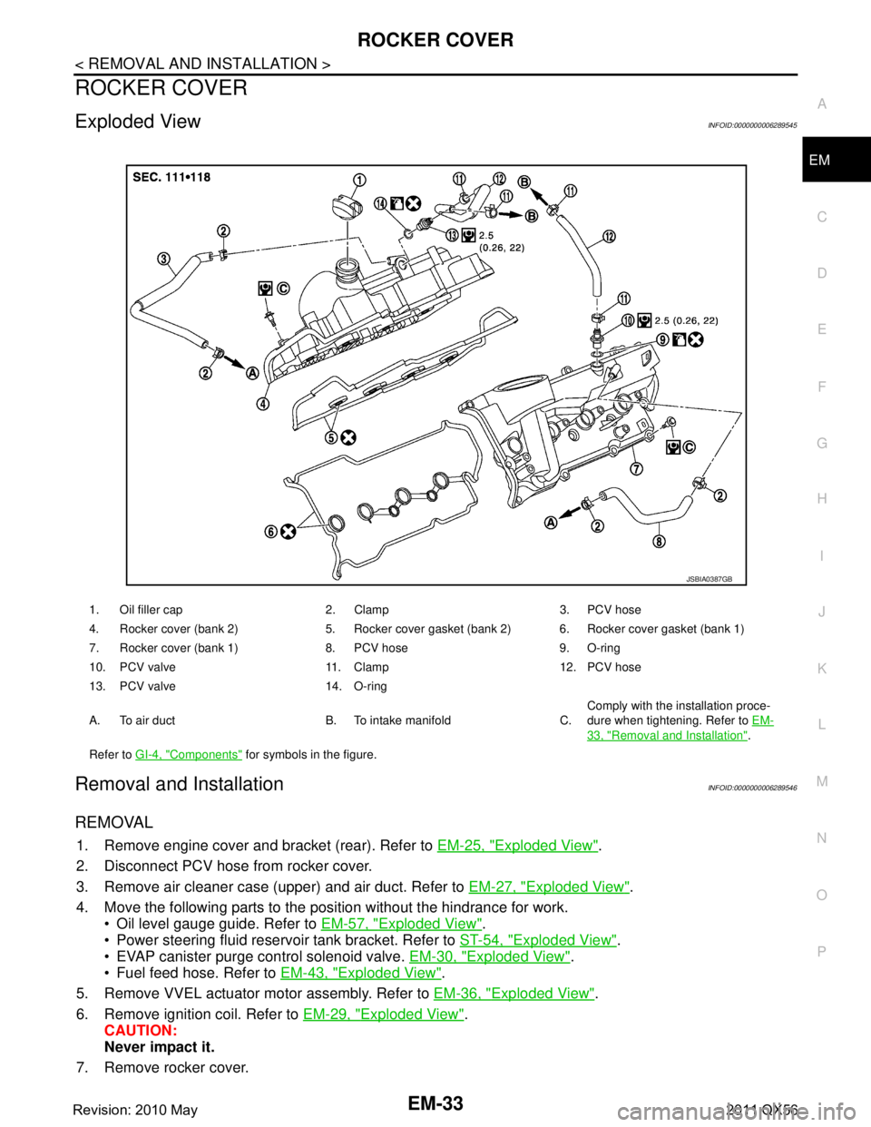
1. Oil filler cap 2. Clamp 3. PCV hose
4. Rocker cover (bank 2) 5. Rocker cover gasket (bank 2) 6. Rocker cover gasket (bank 1)
7. Rocker cover (bank 1) 8. PCV hose 9. O-ring
10. PCV valve 11. Clamp 12. PCV hose
13. PCV valve 14. O-ring
A. To air duct B. To intake manifold C. Comply with the installation proce-
dure when tightening. Refer to
EM-
33, "Removal and Installation".
Refer to GI-4, "
Components" for symbols in the figure.
JSBIA0387GB
Revision: 2010 May2011 QX56
Page 2596 of 5598

EM-34
< REMOVAL AND INSTALLATION >
ROCKER COVER
Loosen bolts in reverse order shown in the figure.
8. Remove rocker cover gasket from rocker cover.
9. Use scraper to remove all traces of liquid gasket from cylinder head & VVEL ladder assembly.
CAUTION:
Never scratch or damage the mating su rface when cleaning off old liquid gasket.
10. Remove PCV valve from rocker cover, if necessary.
11. Remove oil filler cap from rocker cover, if necessary.
INSTALLATION
1. Apply liquid gasket with the tube presser (commercial service tool) to VVEL ladder assembly (1).
Use Genuine RTV silicone seal ant or equivalent. Refer to
GI-22, "
Recommended Chemical Products and Sealants".
NOTE:
The figure shows an example of bank 1 side.
Apply liquid gasket on the front and rear side of engine first. [5 mm (0.20 in) + 5 mm (0.20 in) side as shown in the figure]
2. Install rocker cover gasket to rocker cover.
3. Install rocker cover. Check that rocker cover gasket does not drop fr om the installation groove of rocker cover.
A: Bank 2
B: Bank 1
: Engine front
JPBIA3481ZZ
A : Liquid gasket application point
F : End surface of VVEL ladder assembly
b : 4.0 mm (0.16 in)
c : 2.5 - 3.5 mm (0.098 - 0.138 in)
d : 5.0 mm (0.20 in)
e : 10.0 mm (0.39 in)
: Engine front
JPBIA3480ZZ
Revision: 2010 May2011 QX56
Page 2597 of 5598
ROCKER COVEREM-35
< REMOVAL AND INSTALLATION >
C
DE
F
G H
I
J
K L
M A
EM
NP
O
4. Tighten bolts in two steps separately in numerical order as
shown in the figure.
Because of the limited working space, use adapter and torquewrench assembly [SST: KV10119300 ( — )] (A) to tighten
bolts (on the No.7 and No. 8 cylinders) to the specified torque.
5. Install ignition coil. Refer to EM-29, "
Exploded View".
CAUTION:
Install Ignition coil marked with an identification mark (A)
on cylinder No. 5, 6, 7 and 8.
6. Install VVEL actuator motor assembly. Refer to EM-36, "
Exploded View".
7. Install in the reverse order of removal.
A: Bank 2
B: Bank 1
: Engine front
1st step : 2.0 N·m (0.2 kg-m, 18 in-lb)
2nd step : 8.3 N·m (0.85 kg-m, 73 in-lb)
JPBIA3481ZZ
: Engine front
JPBIA2622ZZ
: Engine front
JPBIA3471ZZ
Revision: 2010 May2011 QX56